CHRYSLER 300 2015 2.G Owners Manual
Manufacturer: CHRYSLER, Model Year: 2015, Model line: 300, Model: CHRYSLER 300 2015 2.GPages: 574, PDF Size: 14.59 MB
Page 301 of 574
select “Yes” to restore, or “Cancel” to exit. Once the
settings are restored, a pop up appears stating#settings
reset to default.#Press the okay button on the touchscreen
to exit.
Clear Personal Data
After pressing the “Clear Personal Data Settings” button
on the touchscreen the following settings will be avail-
able:
•Clear Personal Data
When this feature is selected it will remove personal data
including Bluetooth® devices and presets. To remove
personal information, press the “Clear Personal Data”
button and a pop-up will appear asking#Are you sure
you want to clear all personal data?” select “OK” to
Clear, or “Cancel” to exit. Once the data has been cleared,
a pop up appears stating#Personal data cleared”. Press
the back arrow button on the touchscreen to return to the
previous menu.
System Information
After pressing the “System Information” button on the
touchscreen the following information will be available:
•System Information
When System Information is selected, a System Informa-
tion screen will appear displaying the system software
version.
Uconnect® RADIOS — IF EQUIPPED
For detailed information about your Uconnect® radio,
refer to your Uconnect® Supplement Manual.
4
UNDERSTANDING YOUR INSTRUMENT PANEL 299
Page 302 of 574
iPod®/USB/MP3 CONTROL
This feature allows an iPod® or an external USB device to
be plugged into the USB port.
iPod® control supports Mini, 4G, Photo, Nano, 5G iPod®
and iPhone® devices. Some iPod® software versions
may not fully support the iPod® control features. Please
visit Apple’s website for software updates.
The Media hub also allows the use of an SD card. For
further information, refer to the Uconnect® Supplement
Manual.
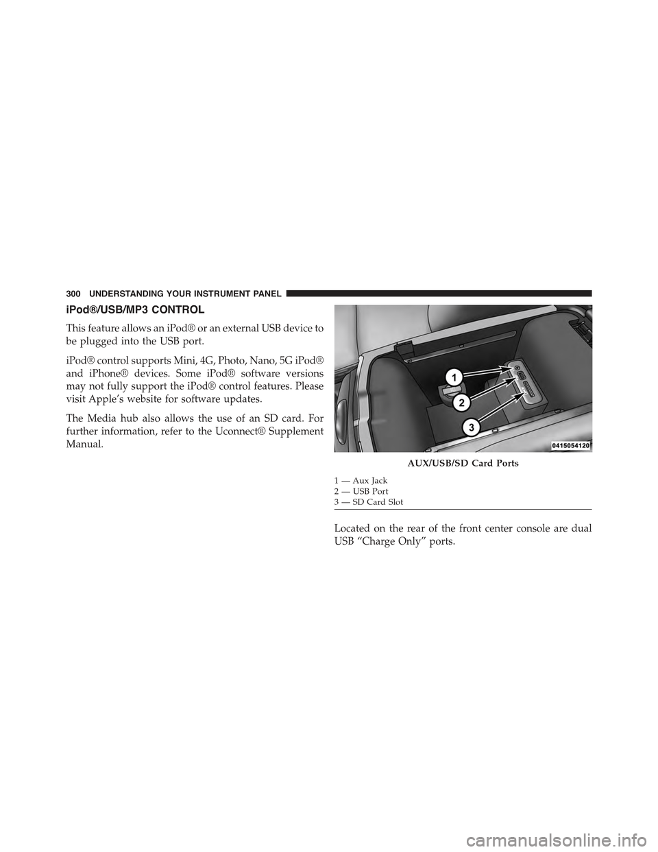
Located on the rear of the front center console are dual
USB “Charge Only” ports.
AUX/USB/SD Card Ports
1 — Aux Jack2—USBPort3—SDCardSlot
300 UNDERSTANDING YOUR INSTRUMENT PANEL
Page 303 of 574
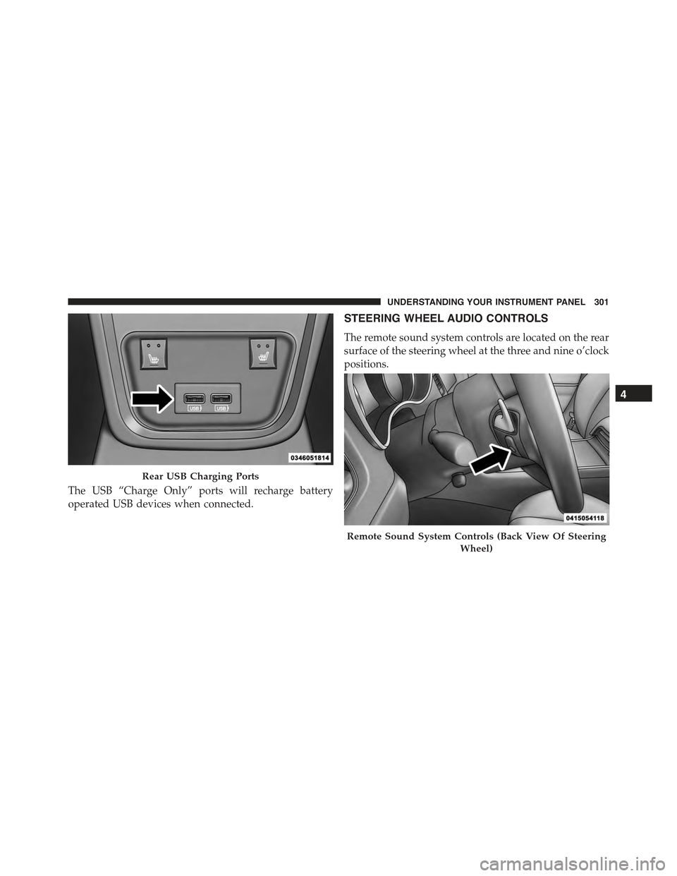
The USB “Charge Only” ports will recharge battery
operated USB devices when connected.
STEERING WHEEL AUDIO CONTROLS
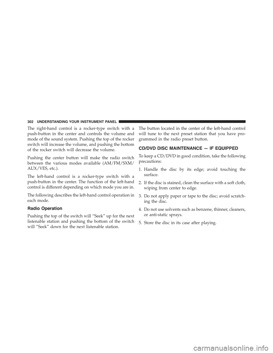
The remote sound system controls are located on the rear
surface of the steering wheel at the three and nine o’clock
positions.
Rear USB Charging Ports
Remote Sound System Controls (Back View Of Steering
Wheel)
4
UNDERSTANDING YOUR INSTRUMENT PANEL 301
Page 304 of 574
The right-hand control is a rocker-type switch with a
push-button in the center and controls the volume and
mode of the sound system. Pushing the top of the rocker
switch will increase the volume, and pushing the bottom
of the rocker switch will decrease the volume.
Pushing the center button will make the radio switch
between the various modes available (AM/FM/SXM/
AUX/VES, etc.).
The left-hand control is a rocker-type switch with a
push-button in the center. The function of the left-hand
control is different depending on which mode you are in.
The following describes the left-hand control operation in
each mode.
Radio Operation
Pushing the top of the switch will “Seek” up for the next
listenable station and pushing the bottom of the switch
will “Seek” down for the next listenable station.
The button located in the center of the left-hand control
will tune to the next preset station that you have pro-
grammed in the radio preset button.
CD/DVD DISC MAINTENANCE — IF EQUIPPED
To keep a CD/DVD in good condition, take the following
precautions:
1. Handle the disc by its edge; avoid touching the
surface.
2. If the disc is stained, clean the surface with a soft cloth,
wiping from center to edge.
3. Do not apply paper or tape to the disc; avoid scratch-
ing the disc.
4. Do not use solvents such as benzene, thinner, cleaners,
or anti-static sprays.
5. Store the disc in its case after playing.
302 UNDERSTANDING YOUR INSTRUMENT PANEL
Page 305 of 574
6. Do not expose the disc to direct sunlight.
7. Do not store the disc where temperatures may become
too high.
NOTE:If you experience difficulty in playing a particular
disc, it may be damaged (e.g., scratched, reflective coat-
ing removed, a hair, moisture or dew on the disc)
oversized, or have protection encoding. Try a known
good disc before considering disc player service.
RADIO OPERATION AND MOBILE PHONES
Under certain conditions, the mobile phone being on in
your vehicle can cause erratic or noisy performance from
your radio. This condition may be lessened or eliminated
by relocating the mobile phone antenna. This condition is
not harmful to the radio. If your radio performance does
not satisfactorily “clear” by the repositioning of the
antenna, it is recommended that the radio volume be
turned down or off during mobile phone operation when
not using Uconnect® (if equipped).
CLIMATE CONTROLS
The air conditioning and heating system is designed to
make you comfortable in all types of weather. This
system can be operated through either the controls on the
instrument panel or through the Uconnect® system dis-
play.
When the Uconnect® system is in different modes (Ra-
dio, Player, Settings, More, etc.) the driver and passenger
temperature settings will be indicated at the top of the
display.
4
UNDERSTANDING YOUR INSTRUMENT PANEL 303
Page 306 of 574
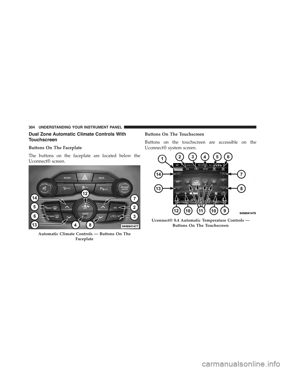
Dual Zone Automatic Climate Controls With
Touchscreen
Buttons On The Faceplate
The buttons on the faceplate are located below the
Uconnect® screen.
Buttons On The Touchscreen
Buttons on the touchscreen are accessible on the
Uconnect® system screen.
Automatic Climate Controls — Buttons On The
Faceplate
Uconnect® 8.4 Automatic Temperature Controls —
Buttons On The Touchscreen
304 UNDERSTANDING YOUR INSTRUMENT PANEL
Page 307 of 574
Button Descriptions (Applies To Both Buttons On The
Faceplate And Buttons On The Touchscreen)
1. MAX A/C Button
Press and release to change the current setting, the
indicator illuminates when MAX A/C is ON. Performing
this function again will cause the MAX A/C operation to
switch into manual mode and the MAX A/C indicator
will turn off.
2. A/C Button
Press and release to change the current setting, the
indicator illuminates when A/C is ON. Performing this
function again will cause the A/C operation to switch
into manual mode and the A/C indicator will turn off.
3. Recirculation Button
Press and release to change the current setting, the
indicator illuminates when ON.
4. AUTO Operation Button
Automatically controls the interior cabin temperature by
adjusting airflow distribution and amount. Performing
this function will cause the system to switch between
manual mode and automatic modes. Refer to “Automatic
Operation” for more information.
5. Front Defrost Button
Press and release to change the current airflow setting to
Defrost mode. The indicator illuminates when this fea-
ture is ON. Air comes from the windshield and side
window demist outlets. When the defrost button is
selected, the blower level will increase. Use Defrost mode
with maximum temperature settings for best windshield
and side window defrosting and defogging. Performing
this function will cause the ATC to switch into manual
mode. If the front defrost mode is turned off the climate
system will return the previous setting.
4
UNDERSTANDING YOUR INSTRUMENT PANEL 305
Page 308 of 574
6. Rear Defrost Button
Press and release this button to turn on the rear window
defroster and the heated outside mirrors (if equipped).
An indicator will illuminate when the rear window
defroster is on. The rear window defroster automatically
turns off after 10 minutes.
CAUTION!
Failure to follow these cautions can cause damage to
the heating elements:
•Use care when washing the inside of the rear
window. Do not use abrasive window cleaners on
the interior surface of the window. Use a soft cloth
and a mild washing solution, wiping parallel to the
heating elements. Labels can be peeled off after
soaking with warm water.
(Continued)
CAUTION!(Continued)
•Do not use scrapers, sharp instruments, or abrasive
window cleaners on the interior surface of the
window.
•Keep all objects a safe distance from the window.
7. Passenger Temperature Control Up Button
Provides the passenger with independent temperature
control. Push the button on the faceplate for warmer
temperature settings or on the touchscreen, press and
slide the temperature bar button towards the red arrow
for warmer temperature settings.
NOTE:Pressing this button while in Sync mode will
automatically exit Sync.
306 UNDERSTANDING YOUR INSTRUMENT PANEL
Page 309 of 574
8. Passenger Temperature Control Down Button
Provides the passenger with independent temperature
control. Push the button on the faceplate for cooler
temperature settings or on the touchscreen, press and
slide the temperature bar button towards the blue arrow
for cooler temperature settings.
NOTE:Pressing this button while in Sync mode will
automatically exit Sync.
9. SYNC
Press the Sync button on the touchscreen to toggle the
Sync feature On/Off. The Sync indicator is illuminated
when this feature is enabled. Sync is used to synchronize
the passenger temperature setting with the driver tem-
perature setting. Changing the passenger temperature
setting while in Sync will automatically exit this feature.
10. Blower Control
Blower control is used to regulate the amount of air
forced through the climate system. There are seven
blower speeds available. Adjusting the blower will cause
automatic mode to switch to manual operation. The
speeds can be selected using either the blower control
knob on the faceplate or the buttons on the touchscreen
as follows:
Blower Control Knob On The Faceplate
The blower speed increases as you turn the blower
control knob clockwise from the lowest blower setting.
The blower speed decreases as you turn the blower
control knob counterclockwise.
4
UNDERSTANDING YOUR INSTRUMENT PANEL 307
Page 310 of 574
Button On The Touchscreen
Use the small blower icon to reduce the blower setting
and the large blower icon to increase the blower setting.
Blower can also be selected by pressing the blower bar
area between the icons.
11. Modes
The airflow distribution mode can be adjusted so air
comes from the instrument panel outlets, floor outlets,
defrost outlets and demist outlets. The Mode settings are
as follows:
•Panel Mode
Air comes from the outlets in the instrument
panel. Each of these outlets can be individu-
ally adjusted to direct the flow of air. The air vanes of
the center outlets and outboard outlets can be moved
up and down or side to side to regulate airflow
direction. There is a shut off wheel located below the
air vanes to shut off or adjust the amount of airflow
from these outlets.
•Bi-Level Mode
Air comes from the instrument panel outlets
and floor outlets. A slight amount of air is
directed through the defrost and side window demis-
ter outlets.
NOTE:BI-LEVEL mode is designed under comfort con-
ditions to provide cooler air out of the panel outlets and
warmer air from the floor outlets.
•Floor Mode
Air comes from the floor outlets. A slight
amount of air is directed through the defrost
and side window demister outlets.
308 UNDERSTANDING YOUR INSTRUMENT PANEL