spare wheel CHRYSLER 300 2015 2.G User Guide
[x] Cancel search | Manufacturer: CHRYSLER, Model Year: 2015, Model line: 300, Model: CHRYSLER 300 2015 2.GPages: 180, PDF Size: 30.54 MB
Page 3 of 180

INTRODUCTION/WELCOME
WELCOME FROM FCA US LLC . . . . . . . 2
CONTROLS AT A GLANCE
DRIVER COCKPIT...............4INSTRUMENT CLUSTER...........6
GETTING STARTED
KEY FOB . . . . . . . . . . . . . . . . . . . . 8REMOTE START...............10KEYLESS ENTER-N-GO™..........10VEHICLE SECURITY ALARM . .......14SEAT BELT SYSTEMS.............14SUPPLEMENTAL RESTRAINT SYSTEM (SRS)—AIRBAGS . . . . . . . . . . . . . . . . . . 15CHILD RESTRAINTS.............18HEAD RESTRAINTS..............22FRONT SEATS . . . . . . . . . . . . . . . . 24REAR SEAT...................27HEATED SEATS . . . . . . . . . . . . . . . . 27HEATED AND COOLED CUPHOLDERS...28ADJUSTABLE PEDALS............29TILT/TELESCOPING STEERINGCOLUMN . . . . . . . . . . . . . . . . . . . 30
OPERATING YOUR VEHICLE
ENGINE BREAK-INRECOMMENDATIONS............31TURN SIGNAL/WIPER/WASHER/HIGH BEAMLEVER.....................32HEADLIGHT SWITCH............33ELECTRONIC SPEED CONTROL.....35ADAPTIVE CRUISE CONTROL (ACC) . . . 37LANESENSE..................42PA R K V I E W ® R E A R B AC K- U P C A M E R A . . 4 2EIGHT-SPEED AUTOMATICTRANSMISSION................43AUTOSTICK . . . . . . . . . . . . . . . . . . 44AUTOMATIC TEMPERATURE CONTROLS(ATC) . . . . . . . . . . . . . . . . . . . . . 46BLIND SPOT MONITORING........48POWER SUNROOF..............49WIND BUFFETING..............51
ELECTRONICS
YO U R V E H I C L E ' S S O U N D SYS T E M....52IDENTIFYING YOUR RADIO........54Uconnect® ACCESS..............55Uconnect® 8.4A.................71Uconnect® 8.4AN...............94Uconnect® PHONE ..............109STEERING WHEEL AUDIO CONTROLS...118SETTING THE ANALOG CLOCK.....118DRIVER INFORMATION DISPLAY (DID). . 119PROGRAMMABLE FEATURES.......120UNIVERSAL GARAGE DOOR OPENER(HomeLink®)..................121
POWER OUTLETS.............123
UTILITY
TRAILER TOWING WEIGHTS (MAXIMUMTRAILER WEIGHT RATINGS).......124RECREATIONAL TOWING (BEHINDMOTORHOME, ETC.)...........125
WHAT TO DO IN EMERGENCIES
ROADSIDE ASSISTANCE..........126INSTRUMENT CLUSTER WARNINGLIGHTS . . . . . . . . . . . . . . . . . . . . 126INSTRUMENT CLUSTER INDICATORLIGHTS . . . . . . . . . . . . . . . . . . . . 130IF YOUR ENGINE OVERHEATS......132JACKING AND TIRE CHANGING.....132BATTERY LOCATION............139JUMP-STARTING..............139MANUAL PARK RELEASE..........141TOWING A DISABLED VEHICLE.....142FREEING A STUCK VEHICLE.......143EVENT DATA RECORDER (EDR).....144
MAINTAINING YOUR VEHICLE
OPENING THE HOOD . . .........145ENGINE COMPARTMENT — 3.6L.....146ENGINE COMPARTMENT — 5.7L.....148FLUID CAPACITIES . . . . . . . . . . . . . 150FLUIDS, LUBRICANTS, AND GENUINEPA RTS . . . . . . . . . . . . . . . . . . . . . 1 5 0MAINTENANCE PROCEDURES . . . . . . 152MAINTENANCE SCHEDULE . . .....152FUSES.....................157TIRE PRESSURES...............161SPARE TIRES — IF EQUIPPED . . . . . . . 162FUEL DOOR RELEASE ...........164WHEEL AND WHEEL TRIM CARE.....165REPLACEMENT BULBS...........166
CONSUMER ASSISTANCE
FCA US LLC CUSTOMER CENTER . . . . 167FCA CANADA INC. CUSTOMERCENTER...................167PUBLICATIONS ORDERING........167ASSISTANCE FOR THE HEARINGIMPAIRED . . . . . . . . . . . . . . . . . . 167REPORTING SAFETY DEFECTS IN THEUNITED STATES . . . . . . . . . . . . . . . 168
MOPAR® ACCESSORIES
AUTHENTIC ACCESSORIES BYMOPAR® . . . . . . . . . . . . . . . . . . . 169
FREQUENTLY ASKED QUESTIONSFREQUENTLY ASKED QUESTIONS....170
INDEX................... 171
TA B L E O F CO N T E N TS
Page 136 of 180

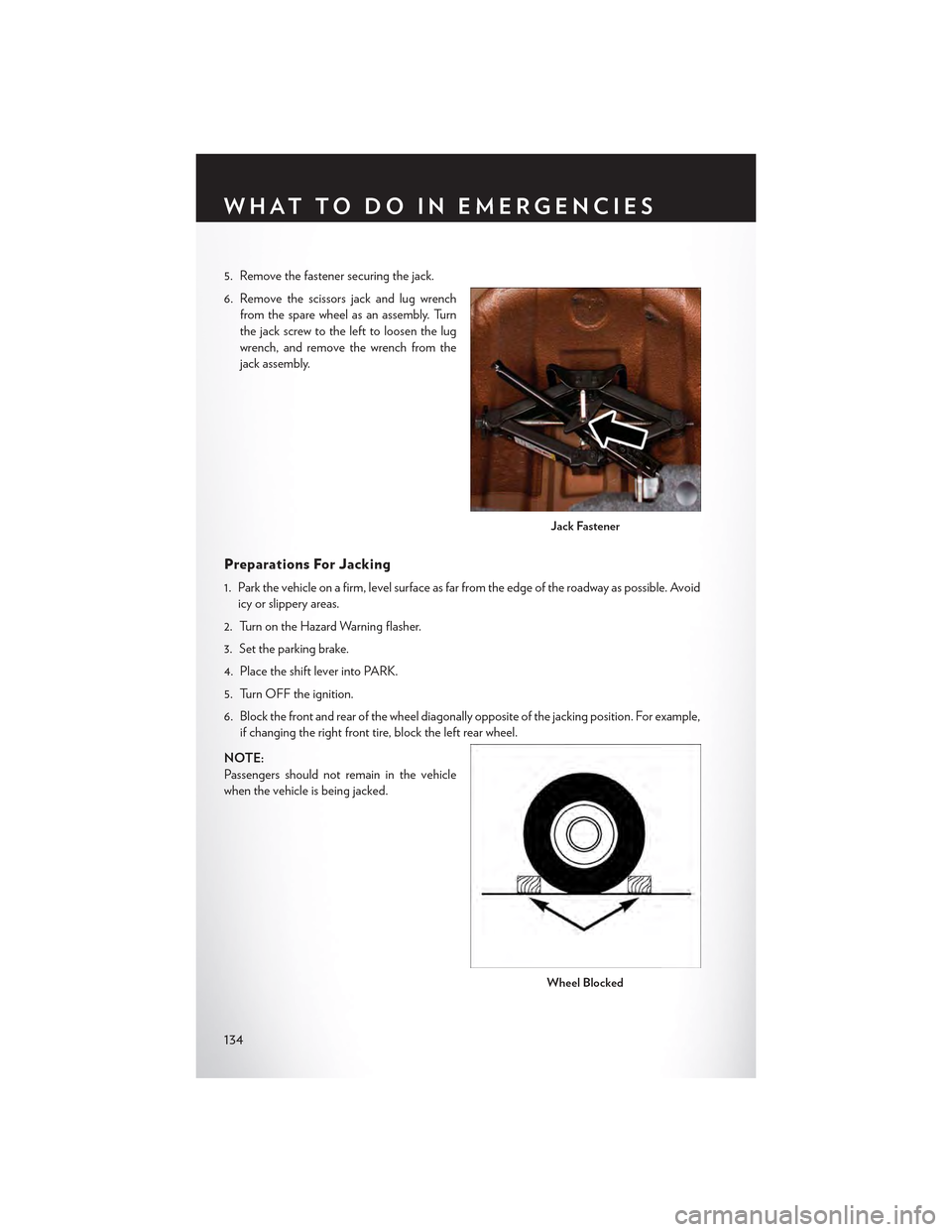
5. Remove the fastener securing the jack.
6. Remove the scissors jack and lug wrench
from the spare wheel as an assembly. Turn
the jack screw to the left to loosen the lug
wrench, and remove the wrench from the
jack assembly.
Preparations For Jacking
1. Park the vehicle on a firm, level surface as far from the edge of the roadway as possible. Avoid
icy or slippery areas.
2. Turn on the Hazard Warning flasher.
3. Set the parking brake.
4. Place the shift lever into PARK.
5. Turn OFF the ignition.
6. Block the front and rear of the wheel diagonally opposite of the jacking position. For example,
if changing the right front tire, block the left rear wheel.
NOTE:
Passengers should not remain in the vehicle
when the vehicle is being jacked.
Jack Fastener
Wheel Blocked
WHAT TO DO IN EMERGENCIES
134
Page 137 of 180

Jacking And Changing A Tire
1. Remove the spare tire, jack, and lug wrench.
2. If equipped with aluminum wheels where
the center cap covers the lug nuts, use the
lug wrench to pry the center cap off care-
fully before raising the vehicle.
3. Before raising the vehicle, use the lug
wrench to loosen, but not remove, the lug
nuts on the wheel with the flat tire. Turn the
lug nuts counterclockwise one turn while the
wheel is still on the ground.
4. Place the jack underneath the lift area that is
closest to the flat tire. Turn the jack screw
clockwise to firmly engage the jack saddle with the lift area of the sill flange.
Jacking Warning Label
WHAT TO DO IN EMERGENCIES
135
Page 139 of 180

7. Mount the spare tire.
NOTE:
•Forvehiclessoequipped,donotattempt
to install a center cap or wheel cover on
the compact spare.
•Referto“CompactSpareTire”andto
“Limited-Use Spare” under “Tires—
General Information” in “Starting and
Operating” in the Owner's Manual on
the DVD for additional warnings, cau-
tions, and information about the spare
tire, its use, and operation.
8. Install the lug nuts with the cone shaped end
of the lug nut toward the wheel. Lightly
tighten the lug nuts.
9. Lower the vehicle to the ground by turning the jack handle counterclockwise.
10. Finish tightening the lug nuts. Push down on the wrench while at the end of the handle for
increased leverage. Tighten the lug nuts in a star pattern until each nut has been tightened
twice. The correct tightness of each lug nut is 130 ft-lb. (176 N·m). If in doubt about the
correct tightness, have them checked with a torque wrench by your authorized dealer or at a
service station.
11. Stow the jack, tools and flat tire. Make sure the base of the jack faces the front of the vehicle
before tightening down the fastener.
Road Tire Installation
1. Mount the road tire on the axle.
2. Install the remaining lug nuts with the cone shaped end of the nut toward the wheel. Lightly
tighten the lug nuts.
3. Lower the vehicle to the ground by turning the jack handle counterclockwise.
4. Finish tightening the lug nuts. Push down on the wrench while at the end of the handle for
increased leverage. Tighten the lug nuts in a star pattern until each nut has been tightened
twice. The correct tightness of each lug nut is 130 ft-lbs (176 N·m). If in doubt about the
correct tightness, have them checked with a torque wrench by your authorized dealer or
service station.
5. After 25 miles (40 km) check the lug nut torque with a torque wrench to ensure that all lug nuts
are properly seated against the wheel.
Install Compact Spare
WHAT TO DO IN EMERGENCIES
137
Page 140 of 180

CAUTION!
Do not attempt to raise the vehicle by jacking on locations other than those indicated in the
Jacking Instructions for this vehicle.
WARNING!
•Donotattempttochangeatireonthesideofthevehicleclosetomovingtraffic.Pullfar
enough off the road to avoid the danger of being hit when operating the jack or changing
the wheel.
•Beingunderajacked-upvehicleisdangerous.Thevehiclecouldslipoffthejackandfallon
you. You could be crushed. Never put any part of your body under a vehicle that is on a
jack.
•Neverstartorruntheenginewhilethevehicleisonajack.Ifyouneedtogetunderaraised
vehicle, take it to a service center where it can be raised on a lift.
• The jack is designed to be used as a tool for changing tires only. The jack should not be
used to lift the vehicle for service purposes. The vehicle should be jacked on a firm level
surface only. Avoid ice or slippery areas.
•Aloosetireorjackthrownforwardinacollisionorhardstopcouldendangertheoccupants
of the vehicle. Always stow the jack parts and the spare tire in the places provided.
•Carefullyfollowthesetirechangingwarningstohelppreventpersonalinjuryordamageto
your vehicle:
•Alwaysparkonafirm,levelsurfaceasfarfromtheedgeoftheroadwayaspossiblebefore
raising the vehicle.
• Turn on the Hazard Warning flasher.
• Block the wheel diagonally opposite the wheel to be raised.
•SettheparkingbrakefirmlyandsetanautomatictransmissioninPARK;amanual
transmission in REVERSE.
•Donotletanyonesitinthevehiclewhenitisonajack.
•Donotgetunderthevehiclewhenitisonajack.
•Onlyusethejackinthepositionsindicatedandforliftingthisvehicleduringatirechange.
•Ifworkingonorneararoadway,beextremelycarefulofmotortraffic.
•Raisingthevehiclehigherthannecessarycanmakethevehiclelessstable.Itcouldslipoff
the jack and hurt someone near it. Raise the vehicle only enough to remove the tire.
•Toavoidtheriskofforcingthevehicleoffthejack,donotfullytightenthewheelnutsuntil
the vehicle has been lowered. Failure to follow this warning may result in personal injury.
•Aloosetireorjackthrownforwardinacollisionorhardstopcouldendangertheoccupants
of the vehicle. Always stow the jack parts and the spare tire in the places provided.
•Thelimited-usesparetiresareforemergencyuseonly.Installationofthislimited-usespare
tire affects vehicle handling. With this tire, do not drive more than 60 mph (100 km/h).
Keep inflated to the cold tire inflation pressure listed on either your tire placard or
limited-use spare tire and wheel assembly. Replace (or repair) the original tire at the first
opportunity and reinstall it on your vehicle. Failure to do so could result in loss of vehicle
control.
WHAT TO DO IN EMERGENCIES
138
Page 159 of 180

FUSES
Front Power Distribution Center (Fuses)
The Front Power Distribution Center is located in the engine compartment. This module
contains fuses and relays.
CAUTION!
•Wheninstallingthepowerdistributioncentercover,itisimportanttoensurethecoveris
properly positioned and fully latched. Failure to do so may allow water to get into the
power distribution center and possibly result in an electrical system failure.
• When replacing a blown fuse, it is important to use only a fuse having the correct
amperage rating. The use of a fuse with a rating other than indicated may result in a
dangerous electrical system overload. If a properly rated fuse continues to blow, it
indicates a problem in the circuit that must be corrected.
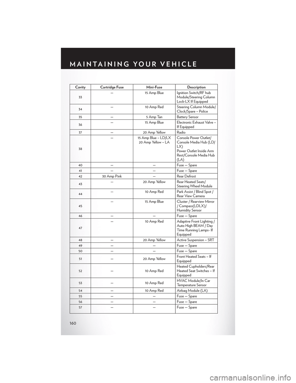
Cavity Cartridge Fuse Mini-FuseDescription
1––Fuse – Spare
2 40 Amp Green–Radiator Fan #1 – If Equipped
3 50 Amp Red–Power Steering #1 / Radiator Fan(6.2L Supercharged) – If Equipped
4 30 Amp Pink–Starter
5 40 Amp Green–Electronic Stability Control
6 30 Amp Pink–Electronic Stability Control
7––Fuse – Spare
8 20 Amp Blue–Police Ignition Run / ACC # 2
9–20 Amp Yellow All-Wheel Drive Module – If Equipped
10–10 Amp Red Security – If Equipped / Under hoodLamp – Police
11–20 Amp YellowHorns
12–10 Amp RedAir Conditioning Clutch
13––Fuse – Spare
14––Fuse – Spare
15–20 Amp YellowLeft HID – If Equipped
16–20 Amp Yellow Right HID – If Equipped
18 50 Amp Red–Radiator Fan #2 – If Equipped
19 50 Amp Red–Power Steering #2 / Radiator Fan(6.2L Supercharged)
20 30 Amp Pink–Wiper Motor
21 30 Amp Pink– Headlamp Washers – If Equipped / Po-lice Feed
MAINTAINING YOUR VEHICLE
157
Page 162 of 180

Cavity Cartridge FuseMini-FuseDescription
33—15 Amp Blue Ignition Switch/RF hubModule/Steering ColumnLock-LX If Equipped
34—10 Amp Red Steering Column Module/Clock/Spare – Police
35—5 Amp Tan Battery Sensor
36—15 Amp Blue Electronic Exhaust Valve –If Equipped
37—20 Amp Yellow Radio
38
—15 Amp Blue – LD/LX20 Amp Yellow – LAConsole Power Outlet/Console Media Hub (LD/LX)Power Outlet Inside ArmRest/Console Media Hub(LA)
40——Fuse — Spare
41——Fuse — Spare
4230 Amp Pink—Rear Defrost
43—20 Amp Yellow Rear Heated Seats/Steering Wheel Module
44—10 Amp Red Park Assist / Blind Spot /Rear View Camera
45—15 Amp Blue Cluster / Rearview Mirror/Compass(LDLX)/Humidity Sensor
46——Fuse — Spare
47
—10 Amp Red Adaptive Front Lighting /Auto High BEAM / DayTi m e R u n n i n g L a m p s- IfEquipped
48—20 Amp Yellow Active Suspension – SRT
49——Fuse — Spare
50——Fuse — Spare
51—20 Amp YellowFront Heated Seats – IfEquipped
52—10 Amp RedHeated Cupholders/RearHeated Seat Switches – IfEquipped
53—10 Amp RedHVAC Module/In CarTemperature Sensor
54—10 Amp Red Airbag Module (LA)
55——Fuse — Spare
56——Fuse — Spare
57——Fuse — Spare
MAINTAINING YOUR VEHICLE
160
Page 164 of 180

WARNING!
•Overloadingofyourtiresisdangerous.Overloadingcancausetirefailure,affectvehicle
handling, and increase your stopping distance. Use tires of the recommended load
capacity for your vehicle.Neveroverloadthem.
• Improperly inflated tires are dangerous and can cause collisions. Under-inflation increases
tire flexing and can result in over-heating and tire failure. Over-inflation reduces a tire’s
ability to cushion shock. Objects on the road and chuck holes can cause damage that
results in tire failure. Unequal tire pressures can cause steering problems. You could lose
control of your vehicle. Over-inflated or under-inflated tires can affect vehicle handling
and can fail suddenly, resulting in loss of vehicle control. Always drive with each tire inflated
to the recommended cold tire inflation pressure.
SPARE TIRES — IF EQUIPPED
NOTE:
For vehicles equipped with Tire Service Kit instead of a spare tire, please refer to “Tire Service Kit”
in “What To Do In Emergencies” on your DVD for further information.
CAUTION!
Because of the reduced ground clearance, do not take your vehicle through an automatic car
wash with a compact or limited-use temporary spare installed. Damage to the vehicle may
result.
Spare Tire Matching Original Equipped Tire And Wheel — If Equipped
Yo u r v e h i c l e m a y b e e q u i p p e d w i t h a s p a r e t i r e a n d w h e e l e q u i v a l e n t i n l o o k a n d f u n c t i o n t o t h e
original equipment tire and wheel found on the front or rear axle of your vehicle. This spare tire
may be used in the tire rotation for your vehicle. If your vehicle has this option, refer to an
authorized tire dealer for the recommended tire rotation pattern.
Compact Spare Tire — If Equipped
The compact spare is for temporary emergency use only. You can identify if your vehicle is
equipped with a compact spare by looking at the spare tire description on the Tire and Loading
Information Placard located on the driver’s side door opening or on the sidewall of the tire.
Compact spare tire descriptions begin with the letter “T” or “S” preceding the size designation.
Example: T145/80D18 103M.
T, S = Temporary Spare Tire
Since this tire has limited tread life, the original equipment tire should be repaired (or replaced)
and reinstalled on your vehicle at the first opportunity.
MAINTAINING YOUR VEHICLE
162
Page 165 of 180

Do not install a wheel cover or attempt to mount a conventional tire on the compact spare wheel,
since the wheel is designed specifically for the compact spare tire. Do not install more than one
compact spare tire and wheel on the vehicle at any given time.
WARNING!
Compact spares are for temporary emergency use only. With these spares, do not drive more
than 50 mph (80 km/h). Temporary use spares have limited tread life. When the tread is worn
to the tread wear indicators, the temporary use spare tire needs to be replaced. Be sure to
follow the warnings, which apply to your spare. Failure to do so could result in spare tire failure
and loss of vehicle control.
Full Size Spare — If Equipped
The full size spare is for temporary emergency use only. This tire may look like the originally
equipped tire on the front or rear axle of your vehicle, but it is not. This spare tire may have limited
tread life. When the tread is worn to the tread wear indicators, the temporary use full size spare
tire needs to be replaced. Since it is not the same as your original equipment tire, replace (or
repair) the original equipment tire and reinstall on the vehicle at the first opportunity.
Limited-Use Spare — If Equipped
The limited-use spare tire is for temporary emergency use only. This tire is identified by a label
located on the limited-use spare wheel. This label contains the driving limitations for this spare.
This tire may look like the original equipped tire on the front or rear axle of your vehicle, but it is
not. Installation of this limited-use spare tire affects vehicle handling. Since it is not the same as
your original equipment tire, replace (or repair) the original equipment tire and reinstall on the
vehicle at the first opportunity.
WARNING!
Limited-use spares are for emergency use only. Installation of this limited-use spare tire affects
vehicle handling. With this tire, do not drive more than the speed listed on the limit-use spare
wheel. Keep inflated to the cold tire inflation pressures listed on your Tire and Loading
Information Placard located on the driver’s side B-P illar or the rear edge of the driver’s side
door. Replace (or repair) the original equipment tire at the first opportunity and reinstall it on
your vehicle. Failure to do so could result in loss of vehicle control.
MAINTAINING YOUR VEHICLE
163
Page 176 of 180

Overheating, Engine...........132
Paddle Shifters...............44
Paddle Shift Mode.............44
Paint Care................152
Panic Alarm.................9
Pedals, Adjustable.............29
Phone, Hands-Free (Uconnect)......109
Phone (Uconnect)............109Placard, Tire And Loading Information . .161PowerDistribution Center (Fuses)......158Glass Sunroof.............49Outlet (Auxiliary Electrical Outlet) . .123Seats.................24Tilt/Telescoping Steering Column . . .30Preparation For Jacking..........134Programmable Electronic Features . . . .120Purchase AppsUconnect Access............58
RadioPresets...............73, 97Rain Sensitive Wiper System........32Rear Camera. . . . . . . . . . . . . . . .42Rear Cross Path . . . . . . . . . . . . . .48Rear Heated Seats.............28Rear ParkSense System..........42Rear Seat, Folding.............27Recreational Towing............125Refrigerant................152Remote ControlTrunk Release..............9Remote Keyless Entry (RKE)Lock The Doors . . . . . . . . . . . . .8Unlock The Doors............8Remote StartingEnter Remote Start Mode.......10Exit Remote Start Mode........10How To Use Remote Start.......10Key Fob . . . . . . . . . . . . . . . .10Remote Starting System........10Remote Starting System..........10Replacement Bulbs............166Reporting Safety Defects.........168Resetting Oil Change Indicator......131Restraint, Head..............22
Schedule, Maintenance..........152
Seat Belt
Child Restraints............18
Seat Belt Maintenance..........152
Seat Belts.................14
Adjustable Shoulder Belt........14
Pretensioners.............14
Seat Belt Warning...........15
Seats....................24Adjustment..............26Head Restraints............22Heated................27Lumbar Support............24Power . . . . . . . . . . . . . . . . .24Security Alarm..............130Security Alarm.............14Selection Of Coolant (Antifreeze) . . . .150Setting The Clock.............118Set Up Your Via Mobile ProfileUconnect...............57ShiftingAutomatic Transmission........43Signals, Turn..............32, 130Sirius Satellite Radio..........74, 98SIRIUS Travel Link............108Spare Tire . . . . . . . . . . ..132, 162, 163Spark Plugs................150SpecificationsFuel (Gasoline)............150Oil . . . . . . . . . . . . . . . . ..150Speed ControlAccel/Decel..............35Distance Setting (ACC Only).....36Mode Setting (ACC Only)......39Speed Control (Cruise Control)......35Sport Mode . . . . . . . . . . . . . . ..131StartingRemote . . . . . . . . . . . . . . . .10SteeringTilt Column..............30Steering Wheel Audio Controls......118Sun Roof . . . . . . . . . . . . . . . . .49Supplemental Restraint System - Air Bag . .15
Temperature Control, Automatic (ATC) . .46Tether Anchor, Child Restraint.......20Text Messaging..............116Tilt Steering Column............30
INDEX
174