interior lights CHRYSLER 300 2020 Owners Manual
[x] Cancel search | Manufacturer: CHRYSLER, Model Year: 2020, Model line: 300, Model: CHRYSLER 300 2020Pages: 328, PDF Size: 14.28 MB
Page 5 of 328

3
EXTERIOR LIGHTS ................................................42 Multifunction Lever ...................................... 42
Headlight Switch .......................................... 42
Daytime Running Lights (DRLs) .................. 43
High/Low Beam Switch ............................... 43
Automatic High Beam — If Equipped ......... 43
Flash-To-Pass ............................................... 44
Automatic Headlights ................................. 44
Parking Lights ............................................. 44
Headlights On With Wipers ......................... 44
Adaptive Bi-Xenon High Intensity
Discharge Headlights — If Equipped........... 44 Headlight Time Delay .................................. 45
Lights-On Reminder .................................... 45
Fog Lights — If Equipped ............................. 45
Turn Signals ................................................ 46
Lane Change Assist — If Equipped ............. 46
INTERIOR LIGHTS ................................................46
Courtesy Lights ............................................ 46
WINDSHIELD WIPERS AND WASHERS .............48
Wiper Operation ........................................... 48
Rain Sensing Wipers — If Equipped ........... 49
CLIMATE CONTROLS ...........................................50
Automatic Climate Control Overview .......... 50
Climate Control Functions ........................... 55
Automatic Temperature Control (ATC) ....... 55
Operating Tips ............................................. 56 WINDOWS ............................................................ 57
Power Window Controls .............................. 57
Wind Buffeting ............................................ 59
PANORAMIC SUNROOF — IF EQUIPPED ........... 59
Opening Sunroof .......................................... 59
Closing Sunroof............................................ 60
Wind Buffeting ............................................ 60
Opening Power Shade ................................. 60
Closing Power Shade................................... 61
Pinch Protect Feature.................................. 61
Sunroof Maintenance.................................. 61
Ignition Off Operation .................................. 61
HOOD ..................................................................... 61
To Open The Hood ...................................... 61
To Close The Hood ....................................... 62
TRUNK.................................................................... 62
Opening ........................................................ 62
Closing .......................................................... 63
Trunk Safety ................................................. 63
Cargo Area Features ................................... 64
LOAD LEVELING SYSTEM — IF EQUIPPED ....... 65
GARAGE DOOR OPENER — IF EQUIPPED ........ 66 Before You Begin Programming
HomeLink® .................................................. 66 Canadian/Gate Operator Programming ..... 68
Using HomeLink®........................................ 69
Security......................................................... 69
Troubleshooting Tips ................................... 69
General Information .................................... 70 INTERNAL EQUIPMENT ........................................70
Storage ......................................................... 70
Cupholders .................................................. 72
Power Sunshade — If Equipped .................. 73
Electrical Power Outlets .............................. 74
Sunglasses Bin Door .................................. 75
GETTING TO KNOW YOUR
INSTRUMENT PANEL
INSTRUMENT CLUSTER .......................................76
Instrument Cluster Descriptions ................ 77
INSTRUMENT CLUSTER DISPLAY .......................78
Location And Controls ................................. 78
Engine Oil Life Reset .................................. 79
Instrument Cluster Display Selectable
Menu Items .................................................. 80 Battery Saver On/Battery Saver Mode
Message — Electrical Load Reduction
Actions — If Equipped ................................. 83
WARNING LIGHTS AND MESSAGES ..................84
Red Warning Lights ..................................... 85
Yellow Warning Lights ................................. 88
Yellow Indicator Lights ................................ 91
Green Indicator Lights ................................. 91
White Indicator Lights ................................. 92
Blue Indicator Lights ................................... 92
ONBOARD DIAGNOSTIC SYSTEM — OBD II ......93
Onboard Diagnostic System (OBD II)
Cybersecurity ............................................... 93
20_LX_OM_EN_USC_t.book Page 3
Page 14 of 328

12GETTING TO KNOW YOUR VEHICLE
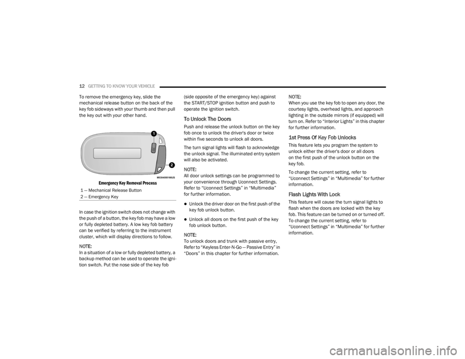
To remove the emergency key, slide the
mechanical release button on the back of the
key fob sideways with your thumb and then pull
the key out with your other hand.
Emergency Key Removal Process
In case the ignition switch does not change with
the push of a button, the key fob may have a low
or fully depleted battery. A low key fob battery
can be verified by referring to the instrument
cluster, which will display directions to follow.
NOTE:
In a situation of a low or fully depleted battery, a
backup method can be used to operate the igni -
tion switch. Put the nose side of the key fob (side opposite of the emergency key) against
the START/STOP ignition button and push to
operate the ignition switch.
To Unlock The Doors
Push and release the unlock button on the key
fob once to unlock the driver's door or twice
within five seconds to unlock all doors.
The turn signal lights will flash to acknowledge
the unlock signal. The illuminated entry system
will also be activated.
NOTE:
All door unlock settings can be programmed to
your convenience through Uconnect Settings.
Refer to “Uconnect Settings” in “Multimedia”
for further information.
Unlock the driver door on the first push of the
key fob unlock button.
Unlock all doors on the first push of the key
fob unlock button.
NOTE:
To unlock doors and trunk with passive entry,
Refer to “Keyless Enter-N-Go — Passive Entry” in
“Doors” in this chapter for further information. NOTE:
When you use the key fob to open any door, the
courtesy lights, overhead lights, and approach
lighting in the outside mirrors (if equipped) will
turn on. Refer to “Interior Lights” in this chapter
for further information.
1st Press Of Key Fob Unlocks
This feature lets you program the system to
unlock either the driver's door or all doors
on the first push of the unlock button on the
key fob.
To change the current setting, refer to
“Uconnect Settings” in “Multimedia” for further
information.
Flash Lights With Lock
This feature will cause the turn signal lights to
flash when the doors are locked with the key
fob. This feature can be turned on or turned off.
To change the current setting, refer to
“Uconnect Settings” in “Multimedia” for further
information.
1 — Mechanical Release Button
2 — Emergency Key
20_LX_OM_EN_USC_t.book Page 12
Page 15 of 328

GETTING TO KNOW YOUR VEHICLE13
Headlight Illumination On Approach
This feature activates the headlights for up to
90 seconds when the doors are unlocked with
the key fob. The time for this feature is
programmable, on vehicles equipped, through
Uconnect Settings. To change the current
setting, refer to “Uconnect Settings” in
“Multimedia” for further information.
To Unlatch The Trunk
Push the trunk button on the key fob two times
within five seconds to unlatch the trunk.
If the vehicle is equipped with Passive Entry,
refer to “Keyless Enter-N-Go — Passive Entry” in
“Doors” in this chapter for further information.
To Lock The Doors And Trunk
Push and release the lock button on the key fob
to lock all doors.
The turn signal lights will flash and the horn will
chirp to acknowledge the signal if programmed.
Refer to “Uconnect Settings” in “Multimedia”
for further programmable information.
NOTE:
To lock the doors with passive entry, refer to
“Keyless Enter-N-Go — Passive Entry” in “Doors”
in this chapter for further information. If one or more doors are open, or the trunk is
open, the doors will lock. The doors will unlock
automatically if the key fob is left inside the
passenger compartment, otherwise the doors
will stay locked.
Sound Horn With Lock
This feature will cause the horn to chirp when the
doors are locked with the key fob. This feature
can be turned on or turned off. To change the
current setting, refer to “Uconnect Settings” in
“Multimedia” for further information.
Using The Panic Alarm
To turn the Panic Alarm feature on or off, push
the Panic button on the key fob. When the Panic
Alarm is activated, the turn signals will flash, the
horn will pulse on and off, and the interior lights
will turn on.
The Panic Alarm will stay on for three minutes
unless you turn it off by either pushing the Panic
button a second time or drive the vehicle at a
speed of 15 mph (24 km/h) or greater.
NOTE:
The interior lights will turn off if you place the
ignition in the ACC or ON/RUN position while the Panic Alarm is activated. However, the
exterior lights and horn will remain on.
You may need to be less than 35 ft (11 m)
from the vehicle when using the key fob to
turn off the Panic Alarm due to the radio
frequency noises emitted by the system.
Key Fob Battery Replacement
The recommended replacement battery is one
CR2032 battery.
NOTE:
Perchlorate Material — special handling may
apply. See www.dtsc.ca.gov/hazard
-
ouswaste/perchlorate for further informa -
tion.
Do not touch the battery terminals that are
on the back housing or the printed circuit
board.
1. Remove the emergency key by sliding the mechanical latch on the back of the key
fob sideways with your thumb and then pull
the emergency key out with your other
hand.
2
20_LX_OM_EN_USC_t.book Page 13
Page 25 of 328

GETTING TO KNOW YOUR VEHICLE23
Security System Manual Override
The vehicle security alarm will not arm if you
lock the doors using the manual door lock.
TO DISARM THE SYSTEM
The vehicle security alarm can be disarmed
using any of the following methods:
Push the unlock button on the key fob.
Grasp the Passive Entry door handle, if
equipped. Refer to “Keyless Enter-N-Go —
Passive Entry” in “Doors” in this chapter for
further information.
Push the Keyless Enter-N-Go ignition button
(requires at least one valid key fob in the
vehicle).
NOTE:
The driver's door key cylinder and the trunk
button on the key fob cannot arm or disarm
the vehicle security alarm.
When the vehicle security alarm is armed,
the interior power door lock switches will not
unlock the doors.
The vehicle security alarm is designed to protect
your vehicle. However, you can create conditions where the system will give you a false
alarm. If one of the previously described arming
sequences has occurred, the vehicle security
alarm will arm regardless of whether you are in
the vehicle or not. If you remain in the vehicle
and open a door, the alarm will sound. If this
occurs, disarm the vehicle security alarm.
If the vehicle security alarm is armed and the
battery becomes disconnected, the vehicle
security alarm will remain armed when the
battery is reconnected; the exterior lights will
flash, the horn will sound. If this occurs, disarm
the vehicle security alarm.
REARMING OF THE SYSTEM
If something triggers the alarm, and no action is
taken to disarm it, the vehicle security alarm will
turn the horn off after 29 seconds, five seconds
between cycles, up to eight cycles if the trigger
remains active and the vehicle security alarm
will rearm itself.
TAMPER ALERT
If something has triggered the vehicle security
alarm in your absence, the horn will sound three
times and the exterior lights will blink three
times when you disarm the vehicle security
alarm. Check the vehicle for tampering.
DOORS
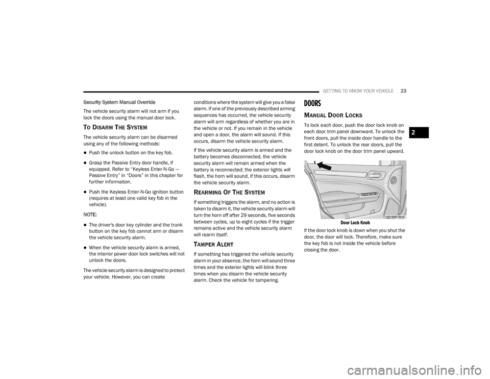
MANUAL DOOR LOCKS
To lock each door, push the door lock knob on
each door trim panel downward. To unlock the
front doors, pull the inside door handle to the
first detent. To unlock the rear doors, pull the
door lock knob on the door trim panel upward.
Door Lock Knob
If the door lock knob is down when you shut the
door, the door will lock. Therefore, make sure
the key fob is not inside the vehicle before
closing the door.
2
20_LX_OM_EN_USC_t.book Page 23
Page 44 of 328

42GETTING TO KNOW YOUR VEHICLE
ILLUMINATED VANITY MIRRORS — IF
E
QUIPPED
An illuminated vanity mirror is located on the
sun visor. To use the mirror, rotate the sun visor
downward and swing the mirror cover upward.
The light turns on automatically. Closing the
mirror cover turns off the light.
Illuminated Vanity Mirror
“Slide-On-Rod” And Extender Features Of
Sun Visor
To use the “Slide-On-Rod” feature of the sun
visor, rotate the sun visor downward and swing
the sun visor so it is parallel to the side window,
grab the sun visor and pull rearwards until the
sun visor is in the desired position. To use the
extender feature of the sun visor, grab the
extender which is located at the rear of the visor
and pull rearward.
Slide-On-Rod Feature
EXTERIOR LIGHTS
MULTIFUNCTION LEVER
The multifunction lever controls the operation
of the turn signals, headlight beam selection
and passing lights. The multifunction lever is
located on the left side of the steering column.
Multifunction Lever
HEADLIGHT SWITCH
The headlight switch is located on the
left side of the instrument panel. This
switch controls the operation of the
headlights, parking lights, instrument
panel lights, interior lights and fog lights (if
equipped).
20_LX_OM_EN_USC_t.book Page 42
Page 48 of 328

46GETTING TO KNOW YOUR VEHICLE
TURN SIGNALS
Move the multifunction lever up or down and
the arrows on each side of the instrument
cluster display flash to show proper operation of
the front and rear turn signal lights.
NOTE:
If either light remains on and does not flash,
or there is a very fast flash rate, check for a
defective outside light bulb. If an indicator
fails to light when the lever is moved, it would
suggest that the indicator bulb is defective.
A “Turn Signal On” message will appear in the
instrument cluster display and a continuous
chime will sound if the vehicle is driven more
than 1 mile (1.6 km) with either turn signal on.
LANE CHANGE ASSIST — IF EQUIPPED
Tap the multifunction lever up or down once,
without moving beyond the detent, and the turn
signal (right or left) will flash three times then
automatically turn off.
INTERIOR LIGHTS
The interior lights come on when a door is
opened.
To protect the battery, the interior lights will turn
off automatically 10 minutes after the ignition is
placed in the OFF position. This will occur if the
interior lights were switched on manually or are
on because a door is open. The Battery
Protection also includes the glove compartment
light and the trunk light. To restore interior light
operation after automatic battery protection is
enabled (lights off), either place the ignition in
the ON/RUN position, or cycle the light switch.
COURTESY LIGHTS
The courtesy lights can be turned on by pushing
the top corner of the lens. To turn the lights off,
push the lens a second time.
Courtesy Lights
20_LX_OM_EN_USC_t.book Page 46
Page 50 of 328

48GETTING TO KNOW YOUR VEHICLE
(Continued)
Dimmer Controls
The dimmer control is part of the headlight
switch and is located on the left side of the
instrument panel.
Instrument Panel Dimmer Control
With the parking lights or headlights on, rotating
the left dimmer control upward will increase the
brightness of the instrument panel lights, radio,
and lighted cupholders (if equipped).
Dome Light Position
Rotate the instrument panel dimmer control
completely upward to the second detent to turn
on the interior lights. The interior lights will
remain on when the instrument panel dimmer
control is in this position. Interior Light Defeat (Off)
Rotate the instrument panel dimmer control to
the extreme bottom (O) off position. The interior
lights will remain off when the doors are open.
Parade Mode (Daytime Brightness Feature)
Rotate the instrument panel dimmer control
upward to the first detent. This feature
brightens all text displays such as the
odometer, instrument cluster display, and radio
when the parking lights or headlights are on.
WINDSHIELD WIPERS AND WASHERS
The multifunction lever operates the windshield
wipers and washer when the ignition is placed
in the ON/RUN or ACC position. The
multifunction lever is located on the left side of
the steering column.
Windshield Wiper/Washer Control
WIPER OPERATION
Rotate the end of the multifunction lever to the
first detent, past the intermittent settings for
low-speed wiper operation, or to the second
detent past the intermittent settings for
high-speed wiper operation.
CAUTION!
Turn the windshield wipers off when driving
through an automatic car wash. Damage to
the windshield wipers may result if the
wiper control is left in any position other
than off.
20_LX_OM_EN_USC_t.book Page 48
Page 74 of 328

72GETTING TO KNOW YOUR VEHICLE
CUPHOLDERS
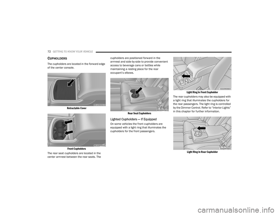
The cupholders are located in the forward edge
of the center console.
Retractable CoverFront Cupholders
The rear seat cupholders are located in the
center armrest between the rear seats. The cupholders are positioned forward in the
armrest and side-by-side to provide convenient
access to beverage cans or bottles while
maintaining a resting place for the rear
occupant’s elbows.
Rear Seat Cupholders
Lighted Cupholders — If Equipped
On some vehicles the front cupholders are
equipped with a light ring that illuminates the
cupholders for the front passengers.
Light Ring In Front Cupholder
The rear cupholders may also be equipped with
a light ring that illuminates the cupholders for
the rear passengers. The light ring is controlled
by the Dimmer Control. Refer to “Interior Lights”
in this chapter for further information.
Light Ring In Rear Cupholder
20_LX_OM_EN_USC_t.book Page 72
Page 86 of 328

84GETTING TO KNOW YOUR INSTRUMENT PANEL
115 Volts AC Power Inverter System
Audio and Telematics System
Loss of the battery charge may indicate one or
more of the following conditions:
The charging system cannot deliver enough
electrical power to the vehicle system
because the electrical loads are larger than
the capability of the charging system. The
charging system is still functioning properly.
Turning on all possible vehicle electrical
loads (e.g. HVAC to max settings, exterior and
interior lights, overloaded power outlets
+12 Volts, 115 Volts AC, USB ports) during
certain driving conditions (city driving,
towing, frequent stopping).
Installing options like additional lights,
upfitter electrical accessories, audio
systems, alarms and similar devices.
Unusual driving cycles (short trips separated
by long parking periods).
The vehicle was parked for an extended
period of time (weeks, months).
The battery was recently replaced and was
not charged completely.
The battery was discharged by an electrical
load left on when the vehicle was parked.
The battery was used for an extended period
with the engine not running to supply radio,
lights, chargers, +12 Volt portable appli -
ances like vacuum cleaners, game consoles
and similar devices.
What to do when an electrical load reduction
action message is present (“Battery Saver On”
or “Battery Saver Mode”)
During a trip:
Reduce power to unnecessary loads if
possible:
Turn off redundant lights (interior or exte -
rior)
Check what may be plugged in to power
outlets +12 Volts, 115 Volts AC, USB
ports
Check HVAC settings (blower, tempera -
ture)
Check the audio settings (volume)
After a trip:
Check if any aftermarket equipment was
installed (additional lights, upfitter electrical accessories, audio systems, alarms) and
review specifications if any (load and Ignition
Off Draw currents).
Evaluate the latest driving cycles (distance,
driving time and parking time).
The vehicle should have service performed if
the message is still present during consecu
-
tive trips and the evaluation of the vehicle
and driving pattern did not help to identify the
cause.
WARNING LIGHTS AND MESSAGES
The warning/indicator lights will illuminate in
the instrument panel together with a dedicated
message and/or acoustic signal when
applicable. These indications are indicative and
precautionary and as such must not be
considered as exhaustive and/or alternative to
the information contained in the Owner’s
Manual, which you are advised to read carefully
in all cases. Always refer to the information in
this chapter in the event of a failure indication.
All active warning lights will display first if
applicable. The system check menu may
appear different based upon equipment
options and current vehicle status. Some
warning lights are optional and may not appear.
20_LX_OM_EN_USC_t.book Page 84
Page 131 of 328

SAFETY129
(Continued)
Enhanced Accident Response System
In the event of an impact, if the communication
network remains intact, and the power remains
intact, depending on the nature of the event,
the ORC will determine whether to have the
Enhanced Accident Response System perform
the following functions:
Cut off fuel to the engine (if equipped).
Cut off battery power to the electric motor (if
equipped).
Flash hazard lights as long as the battery has
power.
Turn on the interior lights, which remain on
as long as the battery has power or for
15 minutes from the intervention of the
Enhanced Accident Response System.
Unlock the power door locks.
Your vehicle may also be designed to perform
any of these other functions in response to the
Enhanced Accident Response System:
Turn off the Fuel Filter Heater, Turn off the
HVAC Blower Motor, Close the HVAC Circula -
tion Door
Cut off battery power to the:
Engine
Electric Motor (if equipped)
Electric power steering
Brake booster
Electric park brake
Automatic transmission gear selector
Horn
Front wiper
Headlamp washer pump
NOTE:
After an accident, remember to cycle the igni -
tion to the STOP (OFF/LOCK) position and
remove the key from the ignition switch to avoid
draining the battery. Carefully check the vehicle
for fuel leaks in the engine compartment and on
the ground near the engine compartment and
fuel tank before resetting the system and
starting the engine. If there are no fuel leaks or
damage to the vehicle electrical devices (e.g.
headlights) after an accident, reset the system by following the procedure described below. If
you have any doubt, contact an authorized
dealer.
Enhanced Accident Response System
Reset Procedure
In order to reset the Enhanced Accident
Response System functions after an event, the
ignition switch must be changed from ignition
START or ON/RUN to ignition OFF. Carefully
check the vehicle for fuel leaks in the engine
compartment and on the ground near the
engine compartment and fuel tank before
resetting the system and starting the engine.
Maintaining Your Air Bag System
WARNING!
Modifications to any part of the air bag system
could cause it to fail when you need it. You
could be injured if the air bag system is not
there to protect you. Do not modify the
components or wiring, including adding any
kind of badges or stickers to the steering
wheel hub trim cover or the upper passenger
side of the instrument panel. Do not modify
the front bumper, vehicle body structure, or
add aftermarket side steps or running boards.
4
20_LX_OM_EN_USC_t.book Page 129