fuse CHRYSLER 300 2021 Owners Manual
[x] Cancel search | Manufacturer: CHRYSLER, Model Year: 2021, Model line: 300, Model: CHRYSLER 300 2021Pages: 268, PDF Size: 15.24 MB
Page 57 of 268
GETTING TO KNOW YOUR VEHICLE 55
NOTE:
All accessories connected to the “battery” powered
ou t
lets should be removed or turned off when the
vehicle is not in use to protect the battery against
discharge.
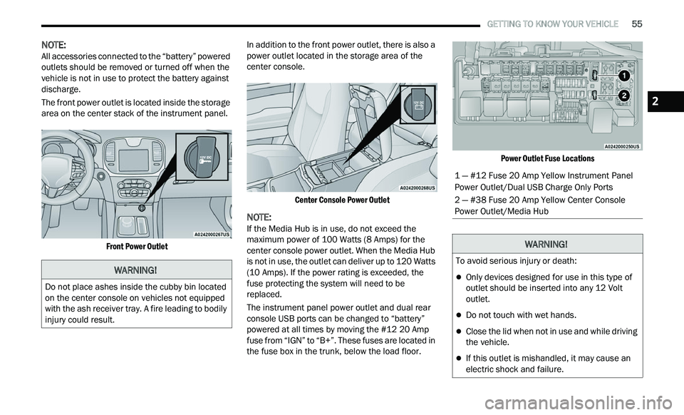
The front power outlet is located inside the storage
ar
ea on the center stack of the instrument panel.
Front Power Outlet
In addition to the front power outlet, there is also a
p
ow
er outlet located in the storage area of the
center console.
Center Console Power Outlet
NOTE:
If the Media Hub is in use, do not exceed the
m a
ximum power of 100 Watts (8 Amps) for the
center console power outlet. When the Media Hub
is not in use, the outlet can deliver up to 120 Watts
(10 Amps). If the power rating is exceeded, the
fuse protecting the system will need to be
replaced.
The instrument panel power outlet and dual rear
c on
sole USB ports can be changed to “battery”
powered at all times by moving the #12 20 Amp
fuse from “IGN” to “B+”. These fuses are located in
the fuse box in the trunk, below the load floor.
Power Outlet Fuse Locations
WARNING!
Do not place ashes inside the cubby bin located
on the center console on vehicles not equipped
with the ash receiver tray. A fire leading to bodily
injury could result.
1 — #12 Fuse 20 Amp Yellow Instrument Panel
Power Outlet/Dual USB Charge Only Ports
2 — #38 Fuse 20 Amp Yellow Center Console
Power Outlet/Media Hub
WARNING!
To avoid serious injury or death:
Only devices designed for use in this type of
outlet should be inserted into any 12 Volt
outlet.
Do not touch with wet hands.
Close the lid when not in use and while driving
the vehicle.
If this outlet is mishandled, it may cause an
electric shock and failure.
2
Page 189 of 268
IN CASE OF EMERGENCY 187
PREPARATIONS FOR JUMP START
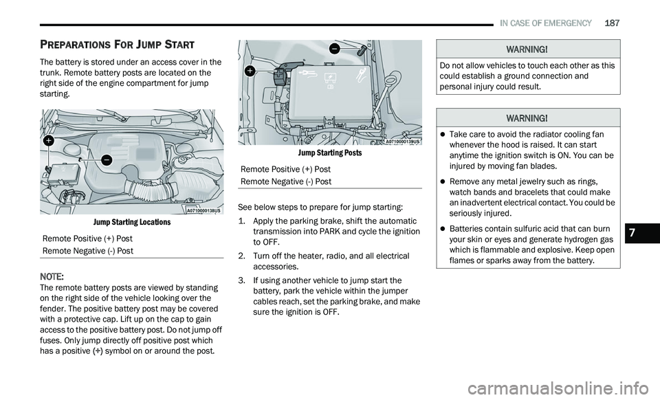
The battery is stored under an access cover in the
trunk. Remote battery posts are located on the
right side of the engine compartment for jump
starting.
Jump Starting Locations
NOTE:
The remote battery posts are viewed by standing
on
the right side of the vehicle looking over the
fender. The positive battery post may be covered
with a protective cap. Lift up on the cap to gain
access to the positive battery post. Do not jump off
fuses. Only jump directly off positive post which
has a positive (+) symbol on or around the post.
Jump Starting Posts
See below steps to prepare for jump starting:
1. Apply the parking brake, shift the automatic t
ransmission into PARK and cycle the ignition
to OFF.
2. T urn off the heater, radio, and all electrical
a
ccessories.
3. If using another vehicle to jump start the b
attery, park the vehicle within the jumper
cables reach, set the parking brake, and make
sure the ignition is OFF.
Remote Positive (+) Post
Remote Negative (-) Post
Remote Positive (+) Post
Remote Negative (-) Post
WARNING!
Do not allow vehicles to touch each other as this
could establish a ground connection and
personal injury could result.
WARNING!
Take care to avoid the radiator cooling fan
whenever the hood is raised. It can start
anytime the ignition switch is ON. You can be
injured by moving fan blades.
Remove any metal jewelry such as rings,
watch bands and bracelets that could make
an inadvertent electrical contact. You could be
seriously injured.
Batteries contain sulfuric acid that can burn
your skin or eyes and generate hydrogen gas
which is flammable and explosive. Keep open
flames or sparks away from the battery.7
Page 190 of 268
188 IN CASE OF EMERGENCY
JUMP STARTING PROCEDURE
NOTE:
Make sure at all times that unused ends of jumper
c a
bles are not contacting each other or either
vehicle while making connections.
Connecting The Jumper Cables
1. C onnect the positive
(
+) end of the jumper
cable to the remote positive (+)
post of the
discharged vehicle.
2. C onnect the opposite end of the positive (
+)
jumper cable to the positive (+) post of the
booster battery.
3. C onnect the negative (
-) end of the jumper
cable to the negative (-) post of the booster
battery. 4. C
onnect the opposite end of the negative (
-)
jumper cable to the remote negative (-) post
(exposed metallic/unpainted post of the
discharge vehicle) located directly behind the
under-hood fuse box.
5. S tart the engine in the vehicle that has the
b
ooster battery, let the engine idle a few
minutes, and then start the engine in the
vehicle with the discharged battery.
6. O nce the engine is started, follow the discon-
n
ection procedure below. Disconnecting The Jumper Cables
1. D
isconnect the negative
(
-) end of the jumper
cable from the remote negative (-)
post of the
discharged vehicle.
2. D isconnect the opposite end of the negative (
-)
jumper cable from the negative (-) post of the
booster battery.
3. D isconnect the positive (
+) end of the jumper
cable from the positive (+) post of the booster
battery.
4. D isconnect the opposite end of the positive (
+)
jumper cable from the remote positive (+) post
of the discharged vehicle.
5. R einstall the protective cover over the remote
p
ositive (+) post of the discharged vehicle.
If frequent jump starting is required to start your
ve
hicle you should have the battery and charging
system tested at an authorized dealer.
WARNING!
Failure to follow this jump starting procedure
could result in personal injury or property
damage due to battery explosion.
CAUTION!
Failure to follow these procedures could result in
damage to the charging system of the booster
vehicle or the discharged vehicle.
WARNING!
Do not connect the jumper cable to the negative
(-) post of the discharged battery. The resulting
electrical spark could cause the battery to
explode and could result in personal injury.
CAUTION!
Do not run the booster vehicle engine above
2,000 rpm since it provides no charging benefit,
w a
stes fuel, and can damage booster vehicle
engine.
CAUTION!
Accessories plugged into the vehicle power
outlets draw power from the vehicle’s battery,
even when not in use (i.e., cellular devices, etc.).
Eventually, if plugged in long enough without
engine operation, the vehicle’s battery will
discharge sufficiently to degrade battery life
and/or prevent the engine from starting.
Page 201 of 268
SERVICING AND MAINTENANCE 199
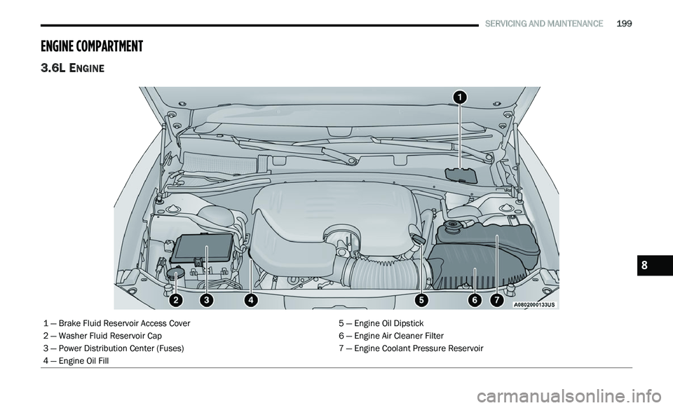
ENGINE COMPARTMENT
3.6L ENGINE
1 — Brake Fluid Reservoir Access Cover 5 — Engine Oil Dipstick
2 — Washer Fluid Reservoir Cap 6 — Engine Air Cleaner Filter
3 — Power Distribution Center (Fuses) 7 — Engine Coolant Pressure Reservoir
4 — Engine Oil Fill
8
Page 202 of 268
200 SERVICING AND MAINTENANCE
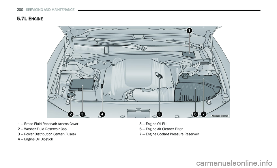
5.7L ENGINE
1 — Brake Fluid Reservoir Access Cover 5 — Engine Oil Fill
2 — Washer Fluid Reservoir Cap 6 — Engine Air Cleaner Filter
3 — Power Distribution Center (Fuses) 7 — Engine Coolant Pressure Reservoir
4 — Engine Oil Dipstick
Page 216 of 268
214 SERVICING AND MAINTENANCE
FUSES
General Information
The fuses protect electrical systems against
excessive current.
When a device does not work, you must check the
fu
se element inside the blade fuse for a break/
melt.
Also, please be aware that when using power
ou t
lets for extended periods of time with the
engine off may result in vehicle battery discharge.
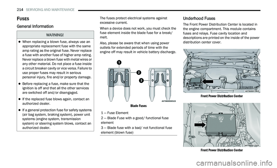
Blade Fuses
Underhood Fuses
The Front Power Distribution Center is located in
the engine compartment. This module contains
fuses and relays. Fuse cavity location and
descriptions are printed on the inside of the power
distribution center cover.
Front Power Distribution Center
Front Power Distribution Center
WARNING!
When replacing a blown fuse, always use an
appropriate replacement fuse with the same
amp rating as the original fuse. Never replace
a fuse with another fuse of higher amp rating.
Never replace a blown fuse with metal wires or
any other material. Do not place a fuse inside
a circuit breaker cavity or vice versa. Failure to
use proper fuses may result in serious
personal injury, fire and/or property damage.
Before replacing a fuse, make sure that the
ignition is off and that all the other services
are switched off and/or disengaged.
If the replaced fuse blows again, contact an
authorized dealer.
If a general protection fuse for safety systems
(air bag system, braking system), power unit
systems (engine system, transmission
system) or steering system blows, contact an
authorized dealer.1 — Fuse Element
2 — Blade Fuse with a good/ functional fuse
element
3 — Blade fuse with a bad/ not functional fuse
el
ement (blown fuse)
Page 217 of 268
SERVICING AND MAINTENANCE 215
CAUTION!
When installing the power distribution center cover, it is important to ensure the cover is properly positioned and fully latched. Failure to do so may allow
water to get into the power distribution center and possibly result in an electrical system failure.
When replacing a blown fuse, it is important to use only a fuse having the correct amperage rating. The use of a fuse with a rating other than indicated may
result in a dangerous electrical system overload. If a properly rated fuse continues to blow, it indicates a problem in the circuit that must be corrected.
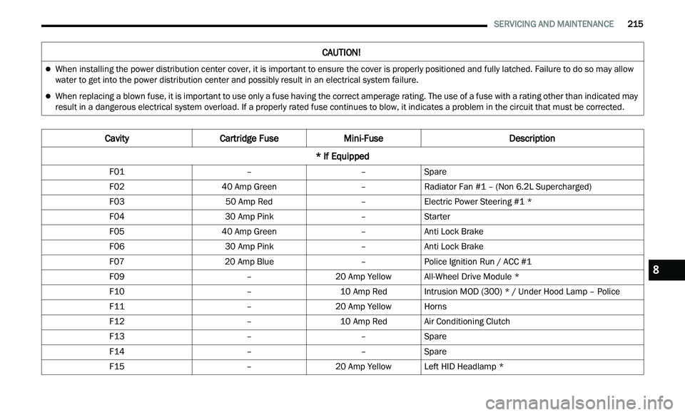
Cavity Cartridge Fuse Mini-Fuse Description
* If Equipped
F01 ––Spare
F02 40 Amp Green –Radiator Fan #1 – (Non 6.2L Supercharged)
F03 50 Amp Red –Electric Power Steering #1 *
F04 30 Amp Pink –Starter
F05 40 Amp Green –Anti Lock Brake
F06 30 Amp Pink –Anti Lock Brake
F07 20 Amp Blue –Police Ignition Run / ACC #1
F09 –20 Amp YellowAll-Wheel Drive Module *
F10 –10 Amp RedIntrusion MOD (300) * / Under Hood Lamp – Police
F11 –20 Amp YellowHorns
F12 –10 Amp RedAir Conditioning Clutch
F13 ––Spare
F14 ––Spare
F15 –20 Amp YellowLeft HID Headlamp *
8
Page 218 of 268
216 SERVICING AND MAINTENANCE
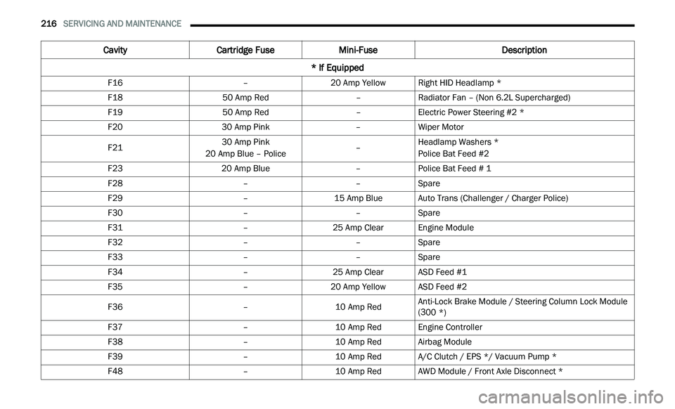
F16 –20 Amp YellowRight HID Headlamp *
F18 50 Amp Red –Radiator Fan – (Non 6.2L Supercharged)
F19 50 Amp Red –Electric Power Steering #2 *
F20 30 Amp Pink –Wiper Motor
F21 30 Amp Pink
20 Amp Blue – Police –Headlamp Washers *
Police Bat Feed #2
F23 20 Amp Blue –Police Bat Feed # 1
F28 ––Spare
F29 –15 Amp BlueAuto Trans (Challenger / Charger Police)
F30 ––Spare
F31 –25 Amp ClearEngine Module
F32 ––Spare
F33 ––Spare
F34 –25 Amp ClearASD Feed #1
F35 –20 Amp YellowASD Feed #2
F36 –10 Amp RedAnti-Lock Brake Module / Steering Column Lock Module
(
3
00 *)
F37 –10 Amp RedEngine Controller
F38 –10 Amp RedAirbag Module
F39 –10 Amp RedA/C Clutch / EPS */ Vacuum Pump *
F48 –10 Amp RedAWD Module / Front Axle Disconnect *
Cavity Cartridge Fuse Mini-Fuse Description
* If Equipped
Page 219 of 268
SERVICING AND MAINTENANCE 217
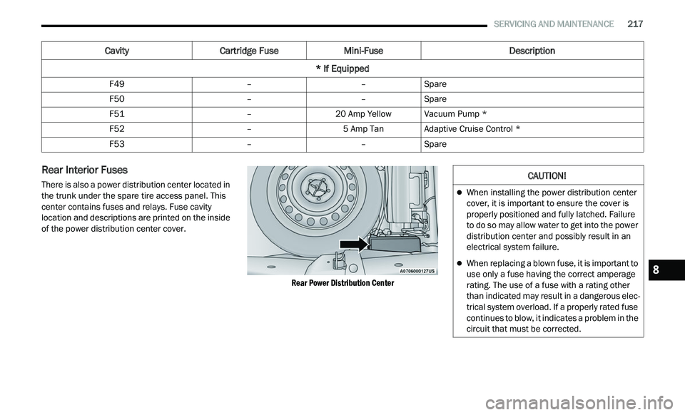
Rear Interior Fuses
There is also a power distribution center located in
the trunk under the spare tire access panel. This
center contains fuses and relays. Fuse cavity
location and descriptions are printed on the inside
of the power distribution center cover.
Rear Power Distribution Center
F49
––Spare
F50 ––Spare
F51 –20 Amp YellowVacuum Pump *
F52 –5 Amp TanAdaptive Cruise Control *
F53 ––Spare
Cavity Cartridge Fuse Mini-Fuse Description
* If Equipped
CAUTION!
When installing the power distribution center
cover, it is important to ensure the cover is
properly positioned and fully latched. Failure
to do so may allow water to get into the power
distribution center and possibly result in an
electrical system failure.
When replacing a blown fuse, it is important to
use only a fuse having the correct amperage
rating. The use of a fuse with a rating other
than indicated may result in a dangerous elec -
trical system overload. If a properly rated fuse
c on
tinues to blow, it indicates a problem in the
circuit that must be corrected.
8
Page 220 of 268
218 SERVICING AND MAINTENANCE
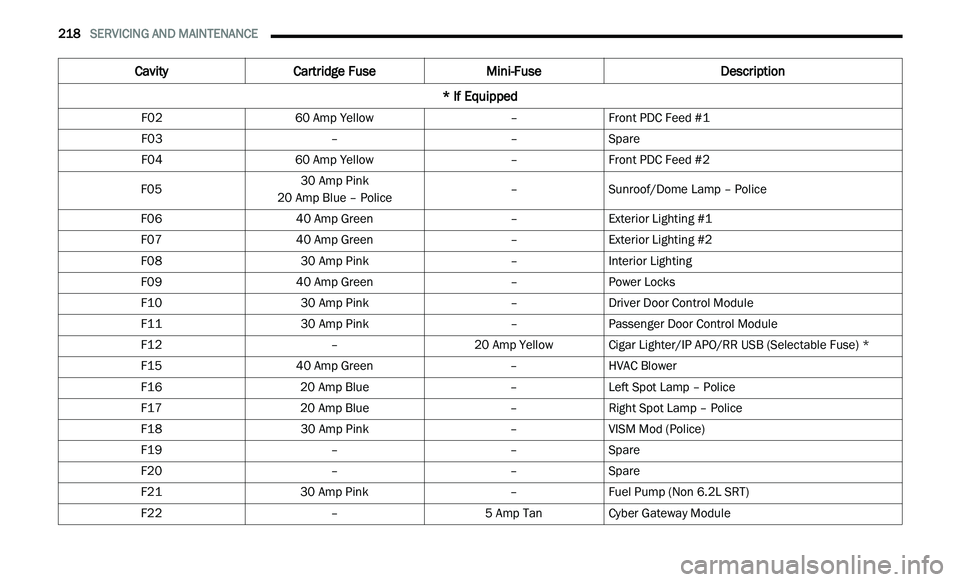
Cavity Cartridge Fuse Mini-Fuse Description
* If Equipped
F02 60 Amp Yellow –Front PDC Feed #1
F03 ––Spare
F04 60 Amp Yellow –Front PDC Feed #2
F05 30 Amp Pink
20 Amp Blue – Police –
Sunroof/Dome Lamp – Police
F06 40 Amp Green –Exterior Lighting #1
F07 40 Amp Green –Exterior Lighting #2
F08 30 Amp Pink –Interior Lighting
F09 40 Amp Green –Power Locks
F10 30 Amp Pink –Driver Door Control Module
F11 30 Amp Pink –Passenger Door Control Module
F12 –20 Amp YellowCigar Lighter/IP APO/RR USB (Selectable Fuse) *
F15 40 Amp Green –HVAC Blower
F16 20 Amp Blue –Left Spot Lamp – Police
F17 20 Amp Blue –Right Spot Lamp – Police
F18 30 Amp Pink –VISM Mod (Police)
F19 ––Spare
F20 ––Spare
F21 30 Amp Pink –Fuel Pump (Non 6.2L SRT)
F22 –5 Amp TanCyber Gateway Module