CHRYSLER 300 2021 Repair Manual
Manufacturer: CHRYSLER, Model Year: 2021, Model line: 300, Model: CHRYSLER 300 2021Pages: 268, PDF Size: 15.24 MB
Page 61 of 268
GETTING TO KNOW YOUR VEHICLE 59
VENTING SUNROOF
Push and release the "Vent" button within one-half
second and the sunroof will open to the vent
position. This is called “Express Vent”, and it will
occur regardless of sunroof position. During
Express Vent operation, any movement of the
switch will stop the sunroof.
NOTE:
If the sunshade is in the closed position when the
v e
nt switch is pushed, the sunshade will automati -
cally cycle to the halfway open position prior to the
s u
nroof opening to the Vent position.
OPENING AND CLOSING THE POWER
S
HADE
Express Open/Close
Push the shade switch rearward and release it
w i
thin one-half second and the shade will
automatically open to the halfway position and
stop automatically. Push the switch again to fully
open the shade.
Push the switch forward and release it within
on e
-half second and the shade will close
automatically from any position.
During Express Open or Express Close operation,
a n
y other movement of the shade switch will stop
the shade. Manual Open/Close
To open the shade, push and hold the switch
r
e
arward. The shade will open and stop
automatically at the half-open position. Push and
hold the switch again and the shade will fully open.
To close the shade, push and hold the switch in the
for
ward position.
Any release of the switch will stop the movement
an
d the shade will remain in a partially closed
condition until the switch is pushed again.
SUNROOF MAINTENANCE
Use only a non-abrasive cleaner and a soft cloth to
clean the glass panel. Periodically check for and
clear out any debris that may have collected in the
tracks.
IGNITION OFF OPERATION
The power sunroof switch can remain active in
Accessory Delay for up to approximately
10 minutes after the vehicle’s ignition is placed to
th
e OFF position. Opening either front door will
cancel this feature.
This feature is programmable using the Uconnect
s y
stem Ú page 122.
HOOD
OPENING THE HOOD
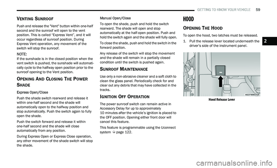
To open the hood, two latches must be released.
1. P ull the release lever located underneath the
d
river’s side of the instrument panel.
Hood Release Lever
2
Page 62 of 268
60 GETTING TO KNOW YOUR VEHICLE
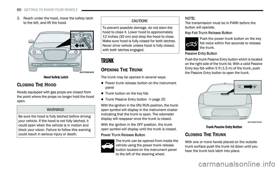
2. Reach under the hood, move the safety latch
to the left, and lift the hood.
Hood Safety Latch
CLOSING THE HOOD
Hoods equipped with gas props are closed from
the point where the props no longer hold the hood
open.
TRUNK
OPENING THE TRUNK
The trunk may be opened in several ways:
Power trunk release button on the instrument
panel
Trunk button on the key fob
Trunk Passive Entry button Ú page 20
With the ignition in the ON/RUN position, the trunk
op e
n symbol will display in the instrument cluster
indicating that the trunk is open. The odometer
display will reappear once the trunk is closed.
With the ignition in the OFF position, the trunk
ope
n symbol will display until the trunk is closed.
Power Trunk Release Button The trunk can be opened from inside the
vehicle using the power trunk release
bu
tton located on the instrument panel
to the left of the steering wheel.
NOTE:
The transmission must be in PARK before the
b u
tton will operate.
Key Fob Trunk Release Button
Push the power trunk button on the key
fob twice within five seconds to release
th
e trunk.
Passive Entry Button
Push the trunk Passive Entry button which is located
o n
the right side of the trunk lid. With a valid Passive
Entry key fob within 5 ft (1.5 m) of the trunk, push
th
e Passive Entry button to open the trunk.
Trunk Passive Entry Button
CLOSING THE TRUNK
With one or more hands placed on the outside
trunk surface push the trunk lid down until you
hear the trunk lock latch into place.
WARNING!
Be sure the hood is fully latched before driving
your vehicle. If the hood is not fully latched, it
could open when the vehicle is in motion and
block your vision. Failure to follow this warning
could result in serious injury or death.
CAUTION!
To prevent possible damage, do not slam the
hood to close it. Lower hood to approximately
12 inches (30 cm) and drop the hood to close.
Ma
ke sure hood is fully closed for both latches.
Never drive vehicle unless hood is fully closed,
with both latches engaged.
Page 63 of 268
GETTING TO KNOW YOUR VEHICLE 61
(Continued)
NOTE:
Before closing the trunk lid make sure your key fob
i s
n’t inside the trunk area. The trunk will latch then
automatically unlock if the key fob is detected, not
allowing the key fob to be locked in the trunk area.
TRUNK SAFETY
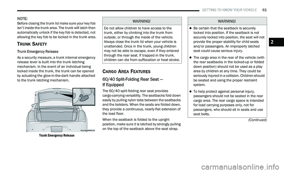
Trunk Emergency Release
As a security measure, a trunk internal emergency
r e
lease lever is built into the trunk latching
mechanism. In the event of an individual being
locked inside the trunk, the trunk can be opened
by actuating the glow-in-the-dark handle attached
to the trunk latching mechanism.
Trunk Emergency Release
CARGO AREA FEATURES
60/40 Split-Folding Rear Seat —
If Equipped
The 60/40 split-folding rear seat provides
cargo-carrying versatility. The seatbacks fold down
easily by pulling nylon tabs between the seatbacks
and the bolsters. When the seats are folded down,
they provide a continuous, nearly-flat extension of
the load floor.
When the seatback is folded to the upright
pos
ition, make sure it is latched by strongly pulling
on the top of the seatback above the seat strap.
WARNING!
Do not allow children to have access to the
trunk, either by climbing into the trunk from
outside, or through the inside of the vehicle.
Always close the trunk lid when your vehicle is
unattended. Once in the trunk, young children
may not be able to escape, even if they entered
through the rear seat. If trapped in the trunk,
children can die from suffocation or heat stroke.
WARNING!
Be certain that the seatback is securely
locked into position. If the seatback is not
securely locked into position, the seat will not
provide the proper stability for child seats
and/or passengers. An improperly latched
seat could cause serious injury.
The cargo area in the rear of the vehicle (with
the rear seatbacks in the locked-up or folded
down position) should not be used as a play
area by children at any time. They could be
seriously injured in a collision. Children should
be seated and using the proper restraint
system.
To help protect against personal injury,
passengers should not be seated in the rear
cargo area. The rear cargo space is intended
for load carrying purposes only, not for
passengers, who should sit in seats and use
seat belts.
2
Page 64 of 268
62 GETTING TO KNOW YOUR VEHICLE
Trunk Mat — If Equipped
A trunk mat covers the bottom of the cargo area.
The trunk mat is used to protect the interior of the
trunk from mud, snow, and debris.
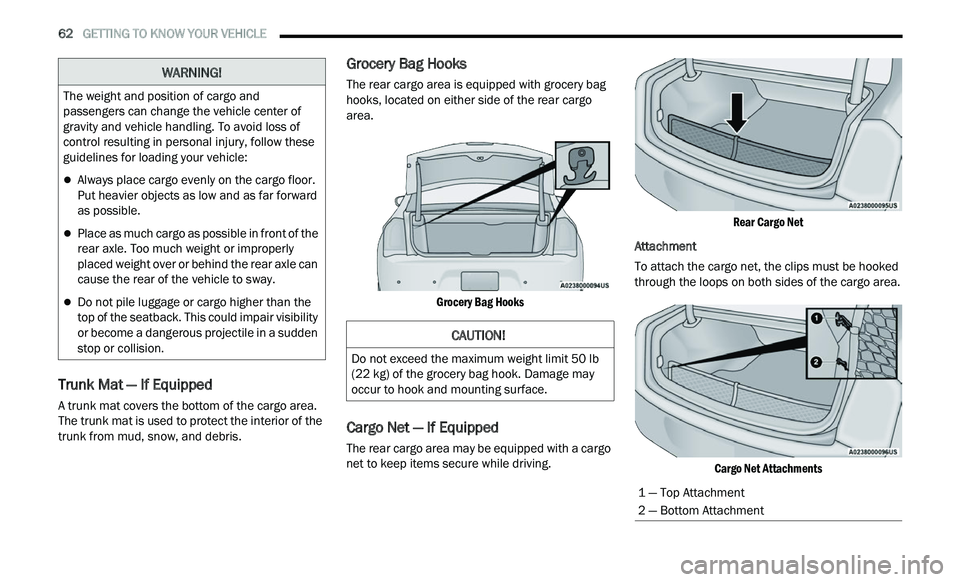
Grocery Bag Hooks
The rear cargo area is equipped with grocery bag
hooks, located on either side of the rear cargo
area.
Grocery Bag Hooks
Cargo Net — If Equipped
The rear cargo area may be equipped with a cargo
net to keep items secure while driving.
Rear Cargo Net
Attachment
To attach the cargo net, the clips must be hooked
t h
rough the loops on both sides of the cargo area.
Cargo Net Attachments
The weight and position of cargo and
pa
ssengers can change the vehicle center of
gravity and vehicle handling. To avoid loss of
control resulting in personal injury, follow these
guidelines for loading your vehicle:
Always place cargo evenly on the cargo floor.
Put heavier objects as low and as far forward
as possible.
Place as much cargo as possible in front of the
rear axle. Too much weight or improperly
placed weight over or behind the rear axle can
cause the rear of the vehicle to sway.
Do not pile luggage or cargo higher than the
top of the seatback. This could impair visibility
or become a dangerous projectile in a sudden
stop or collision.
WARNING!
CAUTION!
Do not exceed the maximum weight limit 50 lb
(22 kg) of the grocery bag hook. Damage may
occur to hook and mounting surface.
1 — Top Attachment
2 — Bottom Attachment
Page 65 of 268
GETTING TO KNOW YOUR VEHICLE 63
LOAD LEVELING SYSTEM — IF EQUIPPED
The automatic load leveling system will provide a
level-riding vehicle under most passenger and
cargo loading conditions.
A hydraulic pump contained within the shock
ab
sorbers raises the rear of the vehicle to the
correct height. It takes approximately 1 mile
(1
.6 km) of driving for the leveling to complete
d e
pending on road surface conditions.
If the leveled vehicle is not moved for
ap
proximately 15 hours, the leveling system will
bleed itself down. The vehicle must be driven to
reset the system.
2
Page 66 of 268
64
GETTING TO KNOW YOUR INSTRUMENT PANEL
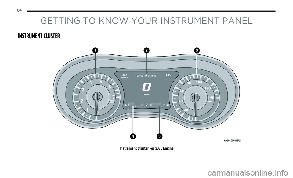
INSTRUMENT CLUSTER
Instrument Cluster For 3.6L Engine
Page 67 of 268
GETTING TO KNOW YOUR INSTRUMENT PANEL 65
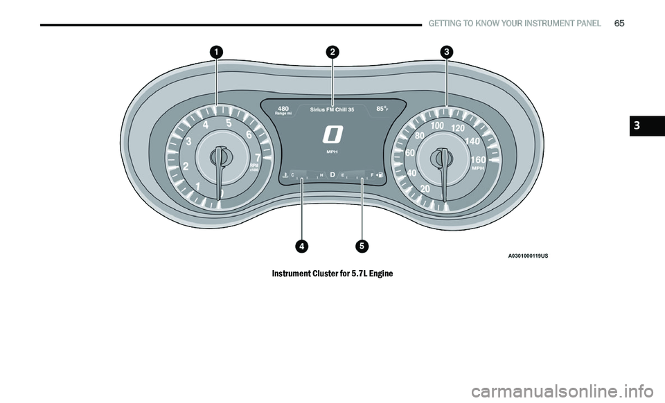
Instrument Cluster for 5.7L Engine
3
Page 68 of 268
66 GETTING TO KNOW YOUR INSTRUMENT PANEL
INSTRUMENT CLUSTER DESCRIPTIONS
1. Tachometer
Indicates the engine speed in revolutions
per minute (RPM x 1000).
2. Instrument Cluster Display
When the appropriate conditions exist, this
display shows the instrument cluster
display messages
Ú page 66.
3. S peedometer
Indicates vehicle speed.
4. T emperature Gauge
The temperature gauge shows engine
coolant temperature. Any reading within the
normal range indicates that the engine
cooling system is operating satisfactorily.
The gauge pointer will likely indicate a
higher temperature when driving in hot
weather, up mountain grades, or when
towing a trailer. It should not be allowed to
exceed the upper limits of the normal oper
-
ating range. 5. Fuel Gauge
The pointer shows the level of fuel in the
fuel tank when the Keyless Push Button
Ignition is in the ON/RUN position.
The fuel pump symbol points to the
side of the vehicle where the fuel
d oor
is located.
NOTE:
The warning / indicator Lights will briefly illuminate
f or
a bulb check when the ignition is first cycled.
INSTRUMENT CLUSTER DISPLAY
Your vehicle is equipped with an instrument cluster
display, which offers useful information to the driver.
With the ignition in the OFF mode, opening/closing
of a door will activate the display for viewing, and
display the total miles, or kilometers, in the odometer. Your instrument cluster display is
designed to display important information about
your vehicle’s systems and features. Using a driver
interactive display located on the instrument panel,
your instrument cluster display can show you how
systems are working and give you warnings when
they are not. The steering wheel mounted controls
allow you to scroll through the main menus and
submenus. You can access the specific information
you want and make selections and adjustments.
LOCATION AND CONTROLS
The instrument cluster display features an
interactive display which is located in the
instrument cluster.
This system conveniently allows the driver to select
a
variety of useful information by pushing the
arrow buttons located on the left side of the
steering wheel. The instrument cluster display
menu items consist of the following:
Speedometer
Vehicle Info
Driver Assist — If Equipped
Fuel Economy
Trip
Audio
Messages
Screen Setup
WARNING!
A hot engine cooling system is dangerous. You or
others could be badly burned by steam or boiling
coolant. It is recommended to call an authorized
dealer for service if your vehicle overheats.
CAUTION!
Driving with a hot engine cooling system could
damage your vehicle. If the temperature gauge
reads “H,” pull over and stop the vehicle. Idle the
vehicle with the air conditioner turned off until
the pointer drops back into the normal range. If
the pointer remains on the “H,” turn the engine
off immediately and call an authorized dealer for
service.
Page 69 of 268
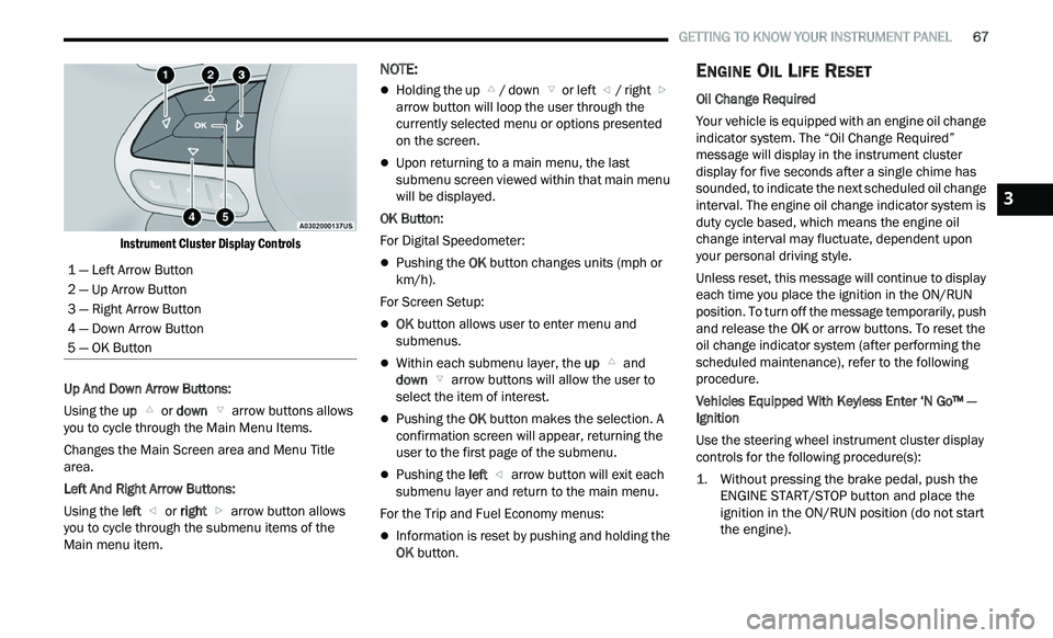
GETTING TO KNOW YOUR INSTRUMENT PANEL 67
Instrument Cluster Display Controls
Up And Down Arrow Buttons:
Using the up
or down arrow buttons allows
you to cycle through the Main Menu Items.
Changes the Main Screen area and Menu Title
a r
ea.
Left And Right Arrow Buttons:
Using the left
or right arrow button allows
you to cycle through the submenu items of the
M a
in menu item.
NOTE:
Holding the up / down or left / right
a
rrow button will loop the user through the
c u
rrently selected menu or options presented
on the screen.
Upon returning to a main menu, the last
submenu screen viewed within that main menu
will be displayed.
OK Button:
For Digital Speedometer:
Pushing the OK button changes units (mph or
km/h).
For Screen Setup:
OK button allows user to enter menu and
submenus.
Within each submenu layer, the up and
down arrow buttons will allow the user to
select the item of interest.
Pushing the OK button makes the selection. A
confirmation screen will appear, returning the
user to the first page of the submenu.
Pushing the left arrow button will exit each
submenu layer and return to the main menu.
For the Trip and Fuel Economy menus:
Information is reset by pushing and holding the
OK button.
ENGINE OIL LIFE RESET
Oil Change Required
Your vehicle is equipped with an engine oil change
in
dicator system. The “Oil Change Required”
message will display in the instrument cluster
display for five seconds after a single chime has
sounded, to indicate the next scheduled oil change
interval. The engine oil change indicator system is
duty cycle based, which means the engine oil
change interval may fluctuate, dependent upon
your personal driving style.
Unless reset, this message will continue to display
e a
ch time you place the ignition in the ON/RUN
position. To turn off the message temporarily, push
and release the OK or arrow buttons. To reset the
oil change indicator system (after performing the
scheduled maintenance), refer to the following
procedure.
Vehicles Equipped With Keyless Enter ‘N Go™ —
I g
nition
Use the steering wheel instrument cluster display
con
trols for the following procedure(s):
1. Without pressing the brake pedal, push the E
NGINE START/STOP button and place the
ignition in the ON/RUN position (do not start
the engine).
1 — Left Arrow Button
2 — Up Arrow Button
3 — Right Arrow Button
4 — Down Arrow Button
5 — OK Button
3
Page 70 of 268
68 GETTING TO KNOW YOUR INSTRUMENT PANEL
2. Push and release the down arrow button to
scroll downward through the main menu to
“ V
ehicle Info.”
3. P ush and release the right
arrow button to
access the ”Oil Life” screen.
4. P ush and hold the O
K button to reset oil life. If
conditions are met, the gauge and numeric
display will update to show 100%. If conditions
are not met a pop-up message of "To reset oil
life engine must be off with ignition in run" will
be displayed (for five seconds), and the user
will remain at the Oil Life screen.
5. P ush and release the u
p or down arrow
button to exit the submenu screen.
NOTE:
If the indicator message illuminates when you start
t h
e vehicle, the oil change indicator system did not
reset. If necessary, repeat this procedure.
Secondary Method Of Resetting Engine Oil Life
1. W ithout pressing the brake pedal, push the
E
NGINE START/STOP button and place the
ignition to the ON/RUN position (do not start
the engine).
2. Fully press the accelerator pedal, slowly, three t
imes within ten seconds.
3. Without pushing the brake pedal, push the E
NGINE START/STOP button once to return the
ignition to the OFF position.
NOTE:
If the indicator message illuminates when you start
t h
e vehicle, the oil change indicator system did not
reset. If necessary, repeat this procedure.
INSTRUMENT CLUSTER DISPLAY
S
ELECTABLE MENU ITEMS
Push and release the up or down arrow
button until the desired Selectable Menu item is
d i
splayed in the instrument cluster display.
Follow the Menu or submenu prompts as desired.
Speedometer
Push and release the OK button to toggle between
mph and km/h.
Vehicle Info
The Vehicle Info consists of the following submenu
(pushing the left or right arrow button will
allow you to scroll through the submenu):
Tire Pressure Monitor
Coolant Temperature
Transmission Temperature
Oil Temperature
Oil Pressure
Oil Life
AWD Status — If Equipped
Battery Voltage
Driver Assist — If Equipped
The Driver Assist menu provides the status and a
visual about the Adaptive Cruise Control and
LaneSense features. When they are both off the
screen, the display will read "Adaptive Cruise
Control (ACC) and LaneSense Off."
Adaptive Cruise Control (ACC) Feature —
If Equipped
The instrument cluster display displays the current
A C
C system settings Ú page 94. The information
displayed depends on ACC system status.
Push the ACC ON/OFF button (located on the
s t
eering wheel) until one of the following displays
in the instrument cluster display:
Adaptive Cruise Control Off
When ACC is deactivated, the display will read
“ A
daptive Cruise Control Off.”
Adaptive Cruise Control Ready
When ACC is activated but the vehicle speed
s e
tting has not been selected, the display will read
“Adaptive Cruise Control Ready.”
Push the SET + or the SET- button (located on the
s t
eering wheel) and the following will display in the
instrument cluster display:
ACC Set
When ACC is set, the set speed will display in the
i n
strument cluster.