turn signal CHRYSLER 300 2021 Owners Manual
[x] Cancel search | Manufacturer: CHRYSLER, Model Year: 2021, Model line: 300, Model: CHRYSLER 300 2021Pages: 268, PDF Size: 15.24 MB
Page 4 of 268
2
INTRODUCTION
SYMBOLS KEY ...........................................................8
VEHICLE MODIFICATIONS/ALTERATIONS .. ...........8
SYMBOL GLOSSARY.. ...............................................8
GETTING TO KNOW YOUR VEHICLE
KEYS ....................................................................... 12
Key Fob .............................................................12
S
ENTRY KEY . . ......................................................... 14
IGNITION SWITCH .. ................................................ 15
Keyless Enter ‘n Go™ — Ignition.. ....................15
REMOTE START — IF EQUIPPED . . ........................ 16
How To Use Remote Start .. ..............................16
To Exit Remote Start Mode . . ...........................17
Remote Start Front Defrost Activation —
If Equipped. .
......................................................17
Remote Start Comfort Systems —
If Equipped. .
......................................................17
Remote Start Cancel Message . . ......................18
VEHICLE SECURITY SYSTEM — IF EQUIPPED . . ... 18
To Arm The System .. ........................................18
To Disarm The System . . ...................................19
Rearming Of The System . . ...............................19
Security System Manual Override . . .................19
Tamper Alert . . ...................................................19 DOORS .
...................................................................19
M
anual Door Locks .. ........................................19
Power Door Locks . . .........................................20
Keyless Enter ‘n Go™ — Passive Entry . . .........20
Automatic Unlock Doors On Exit. . ....................22
Automatic Door Locks — If Equipped . . ............22
Child-Protection Door Lock System —
Rear Doors . .
......................................................23
STEERING WHEEL . . ................................................23
Manual Tilt/Telescoping Steering Column —
If Equipped. .
......................................................23
Power Tilt/Telescoping Steering Column —
If Equipped. .
......................................................24
Heated Steering Wheel — If Equipped . . ..........24
UCONNECT VOICE RECOGNITION QUICK TIPS . . .25
Introducing Uconnect .. .....................................25
Basic Voice Commands . . .................................25
Get Started . . .....................................................25
Additional Information . . ...................................25
DRIVER MEMORY SETTINGS — IF EQUIPPED . . ...26
Programming The Memory Feature .. ..............26
Linking And Unlinking The Key Fob To
Memory . ............................................................27
M
emory Position Recall . . .................................27
SEATS . ....................................................................27
M anual Adjustment (Rear Seats) .. ..................27
Power Adjustment (Front Seats) . . ..................28
Heated Seats — If Equipped . . .........................30
Front Ventilated Seats — If Equipped . . ..........31
Head Restraints . . ............................................32 MIRRORS .
.............................................................. 34
I
nside Rearview Mirror.. ................................... 34
Illuminated Vanity Mirrors . . ............................. 34
Outside Mirrors.................................................3 5
D river's Outside Automatic Dimming
Mirror — If Equipped. .
....................................... 35
Outside Mirrors With Turn Signal And
Approach Lighting — If Equipped . .
.................. 35
Power Mirrors . . ................................................. 35
Power Folding Outside Mirrors —
If Equipped . .
.....................................................36
Heated Mirrors — If Equipped . . ....................... 36
Tilt Side Mirrors In Reverse — If Equipped . . ... 36
UNIVERSAL GARAGE DOOR OPENER
(HOMELINK®) . .
..................................................... 37
Before You Begin Programming
HomeLink® . .
.................................................... 37
Erasing All The HomeLink® Channels . . .......... 37
Identifying Whether You Have A Rolling
Code Or Non-Rolling Code Device . .
................. 37
Programming HomeLink® To A Garage
Door Opener . .
................................................... 38
Programming HomeLink® To A
Miscellaneous Device . .
.................................... 38
Reprogramming A Single HomeLink®
Button . .............................................................. 39
C
anadian/Gate Operator Programming . . ....... 39
Page 5 of 268
3
EXTERIOR LIGHTS ................................................. 40
Headlight Switch.. .............................................40
Multifunction Lever . . ........................................40
Daytime Running Lights (DRLs). . .....................41
High/Low Beam Switch. . ..................................41
Automatic High Beam — If Equipped . . ...........41
Flash-To-Pass. . ..................................................41
Automatic Headlights . . ....................................41
Parking Lights . . ................................................41
Headlights On With Wipers . . ............................42
Adaptive Bi-Xenon High Intensity Discharge
Headlights — If Equipped . .
...............................42
Headlight Time Delay . . .....................................42
Lights-On Reminder . . .......................................42
Fog Lights — If Equipped . . ................................42
Turn Signals . . ....................................................43
Lane Change Assist — If Equipped . . ................43
INTERIOR LIGHTS . . ............................................... 43
Interior Courtesy Lights .. ..................................43
WINDSHIELD WIPERS AND WASHERS . . ............ 45
Windshield Wiper Operation .. ..........................45
Rain Sensing Wipers — If Equipped . . .............46
CLIMATE CONTROLS . . .......................................... 47
Automatic Climate Control Descriptions And
Functions . .........................................................47
A
utomatic Temperature Control (ATC) . . .........49
Climate Voice Commands. . ..............................50
Operating Tips . . ...............................................50 INTERIOR STORAGE AND EQUIPMENT .
.
............. 51
Storage..............................................................51
U SB/AUX Control . . ...........................................53
Lighted Cupholders — If Equipped . . ................53
Heated And Cooled Cupholders —
If Equipped . .
.....................................................53
Power Sunshade — If Equipped . . ....................54
Power Outlets . . .................................................54
WINDOWS . . ............................................................56
Power Window Controls .. .................................56
Automatic Window Features . . ........................56
Reset Auto-Up . . ................................................57
Window Lockout Switch . . .................................57
Wind Buffeting . . ...............................................57
PANORAMIC SUNROOF — IF EQUIPPED . . ...........58
Opening And Closing The Sunroof.. .................58
Pinch Protect Feature . . ....................................58
Venting Sunroof. . ..............................................59
Opening And Closing The Power Shade. . ........59
Sunroof Maintenance . . ....................................59
Ignition Off Operation. . .....................................59
HOOD . .....................................................................59
O pening The Hood.. ..........................................59
Closing The Hood . . ...........................................60
TRUNK . ...................................................................60
O pening The Trunk .. .........................................60
Closing The Trunk. . ...........................................60
Trunk Safety . . ...................................................61
Cargo Area Features . . .....................................61
LOAD LEVELING SYSTEM — IF EQUIPPED . . .......63
GETTING TO KNOW YOUR
INSTRUMENT PANEL
INSTRUMENT CLUSTER ........................................ 64
Instrument Cluster Descriptions .. .................. 66
INSTRUMENT CLUSTER DISPLAY . . ...................... 66
Location And Controls.. .................................... 66
Engine Oil Life Reset . . ..................................... 67
Instrument Cluster Display Selectable
Menu Items . .
.................................................... 68
Battery Saver On/Battery Saver Mode
Message — Electrical Load Reduction
Actions — If Equipped . .
.................................... 70
Programmable Features . . ................................ 71
WARNING LIGHTS AND MESSAGES . . ................. 71
Red Warning Lights .. ........................................72
Yellow Warning Lights . . .................................... 74
Yellow Indicator Lights . . ................................... 77
Green Indicator Lights . . ................................... 77
White Indicator Lights . . .................................... 78
Blue Indicator Lights . . ...................................... 78
ONBOARD DIAGNOSTIC SYSTEM — OBD II . . ...... 79
Onboard Diagnostic System
(OBD II) Cybersecurity . .
.................................... 79
EMISSIONS INSPECTION AND MAINTENANCE
PROGRAMS . .
.......................................................... 79
Page 14 of 268
12
GETTING TO KNOW YOUR VEHICLE
KEYS
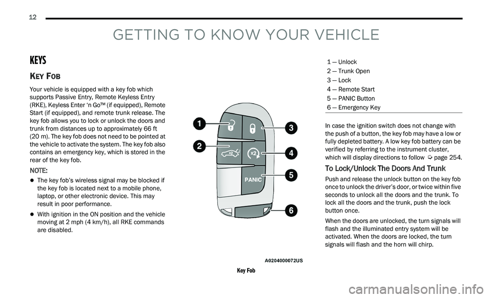
KEY FOB
Your vehicle is equipped with a key fob which
supports Passive Entry, Remote Keyless Entry
(RKE), Keyless Enter ‘n Go™ (if equipped), Remote
Start (if equipped), and remote trunk release. The
key fob allows you to lock or unlock the doors and
trunk from distances up to approximately 66
ft
( 2
0 m). The key fob does not need to be pointed at
t h
e vehicle to activate the system. The key fob also
contains an emergency key, which is stored in the
rear of the key fob.
NOTE:
The key fob’s wireless signal may be blocked if
the key fob is located next to a mobile phone,
laptop, or other electronic device. This may
result in poor performance.
With ignition in the ON position and the vehicle
moving at 2 mph (4 km/h), all RKE commands
a r
e disabled.
Key Fob
In case the ignition switch does not change with
t
h
e push of a button, the key fob may have a low or
fully depleted battery. A low key fob battery can be
verified by referring to the instrument cluster,
which will display directions to follow
Ú page 254.
To Lock/Unlock The Doors And Trunk
Push and release the unlock button on the key fob
once to unlock the driver’s door, or twice within five
seconds to unlock all the doors and the trunk. To
lock all the doors and the trunk, push the lock
button once.
When the doors are unlocked, the turn signals will
fl
ash and the illuminated entry system will be
activated. When the doors are locked, the turn
signals will flash and the horn will chirp.
1 — Unlock
2 — Trunk Open
3 — Lock
4 — Remote Start
5 — PANIC Button
6 — Emergency Key
Page 19 of 268
GETTING TO KNOW YOUR VEHICLE 17
For security, power window operation is
disabled when the vehicle is in the Remote Start
mode.
Remote Start can only be used twice. The igni -
tion must be placed in the ON/RUN position
b e
fore the Remote Start sequence can be
repeated for a third cycle.
All of the following conditions must be met before
t h
e engine will remote start:
Gear selector in PARK
Doors closed
Hood closed
Trunk closed
Hazard switch off
Brake switch inactive (brake pedal not pressed)
Battery at an acceptable charge level
PANIC button not pushed
System not disabled from previous Remote
Start event
Vehicle Security Light is flashing
Ignition in OFF position
Fuel level meets minimum requirement
Vehicle Security system is not signaling an intru -
sion
Malfunction Indicator Light is not illuminated
TO EXIT REMOTE START MODE
To drive the vehicle after starting the Remote Start
system, either push and release the unlock button
on the key fob to unlock the doors, or unlock the
vehicle using Keyless Enter ‘n Go™ — Passive Entry
via the door handles, and disarm the Vehicle
Security system (if equipped). Then, prior to the
end of the 15 minute cycle, push and release the
S T
ART/STOP ignition button.
The Remote Start system will turn the engine off
wi
th another push and release of the Remote Start
button on the key fob, or if the engine is allowed to
run for the entire 15 minute cycle. Once the
i g
nition is placed in the ON/RUN position, the
climate controls will resume the previously set
operations (temperature, blower control, etc.).
NOTE:
To avoid unintentional shutdowns, the system
will disable for two seconds after receiving a
valid Remote Start request.
For vehicles equipped with the Keyless Enter ‘n
Go™ — Passive Entry feature, the message
“Remote Start Active — Push Start Button” will
display in the instrument cluster display until
you push the START/STOP ignition button.
REMOTE START FRONT DEFROST
A
CTIVATION — IF EQUIPPED
When Remote Start is active, and the outside
ambient temperature is 40°F (4.5°C) or below, the
system will automatically activate front defrost for
15 minutes or less. The time is dependent on the
a m
bient temperature. Once the timer expires, the
system will automatically adjust the settings
depending on ambient conditions. See “Remote
Start Comfort Systems — If Equipped” in the next
section for detailed operation.
REMOTE START COMFORT SYSTEMS —
I
F EQUIPPED
When Remote Start is activated, the front and rear
defrost will automatically turn on in cold weather.
The heated steering wheel and driver heated seat
feature will turn on if selected in the comfort menu
screen within Uconnect Settings
Ú page 122.
WARNING!
Do not start or run an engine in a closed
garage or confined area. Exhaust gas contains
Carbon Monoxide (CO) which is odorless and
colorless. Carbon Monoxide is poisonous and
can cause serious injury or death when
inhaled.
Keep key fobs away from children. Operation
of the Remote Start system, windows, door
locks or other controls could cause serious
injury or death.
2
Page 20 of 268
18 GETTING TO KNOW YOUR VEHICLE
In warm weather, the driver vented seat feature
will turn on when Remote Start is activated, if
programmed in the Comfort menu screen. The
vehicle will adjust the climate control settings
depending on the outside ambient temperature.
Automatic Temperature Control (ATC) —
If Equipped
The climate controls will be automatically adjusted
t o
the optimal temperature and mode settings
depending on the outside ambient temperature.
This will occur until the ignition is placed in the ON/
RUN position where the climate controls will
resume their previous settings.
Manual Temperature Control (MTC) — If Equipped
In ambient temperatures at 40°F (4.5°C) or
below, the climate settings will default to
maximum heat, with fresh air entering the
cabin. If the front defrost timer expires, the
vehicle will enter Mix Mode.
In ambient temperatures from 40°F (4.5°C) to
78°F (26°C), the climate settings will be based
on the last settings selected by the driver.
In ambient temperatures at 78°F (26°C) or
above, the climate settings will default to MAX
A/C, Bi-Level Mode, with Recirculation on.
For more information on ATC, MTC, and climate
c on
trol settings, see Ú page 47.
NOTE:
These features will stay on through the duration of
R e
mote Start until the ignition is placed in the ON/
RUN position. The climate control settings will
change if manually adjusted by the driver while the
vehicle is in Remote Start mode, and exit auto -
matic override. This includes the OFF button on the
c l
imate controls, which will turn the system off.
REMOTE START CANCEL MESSAGE
The following messages will display in the
instrument cluster display if the vehicle fails to
remote start or exits Remote Start prematurely:
Remote Start Aborted — Door Open
Remote Start Aborted — Hood Open
Remote Start Aborted — Fuel Low
Remote Start Aborted — Trunk Open
Remote Start Disabled — Start Vehicle To Reset
Remote Start Aborted — Too Cold
Remote Start Aborted — Time Expired
The instrument cluster display message stays
a c
tive until the ignition is placed in the ON/RUN
position
VEHICLE SECURITY SYSTEM — IF EQUIPPED
The Vehicle Security system monitors the vehicle
doors, hood, trunk, and the Keyless Enter ‘n Go™
— Ignition for unauthorized operation. While the Vehicle Security system is armed, interior switches
for door locks and trunk release are disabled. If
something triggers the alarm, the Vehicle Security
system will provide the following audible and
visible signals:
The horn will pulse
The turn signals will flash
The Vehicle Security Light in the instrument
cluster will flash
TO ARM THE SYSTEM
Follow these steps to arm the Vehicle Security
system:
1. Make sure the vehicle’s ignition is placed in
t
he OFF position.
2. Perform one of the following methods to lock t
he vehicle:
Push lock on the interior power door lock
switch with the driver and/or passenger
door open.
Push the lock button on the exterior Passive
Entry door handle with a valid key fob avail -
able in the same exterior zone
Ú page 20.
Push the lock button on the key fob.
3. I f any doors are open, close them.
Page 23 of 268
GETTING TO KNOW YOUR VEHICLE 21
between 0, 30, 60 or 90 seconds. Passive Entry
Unlock also initiates two flashes of the turn
signal lamps.
If wearing gloves, or if it has been raining/
snowing on the Passive Entry door handle, the
unlock sensitivity can be affected, resulting in a
slower response time.
If the vehicle is unlocked by Passive Entry and
no door is opened within 60 seconds, the
vehicle will relock and (if equipped) will arm the
Vehicle Security system.
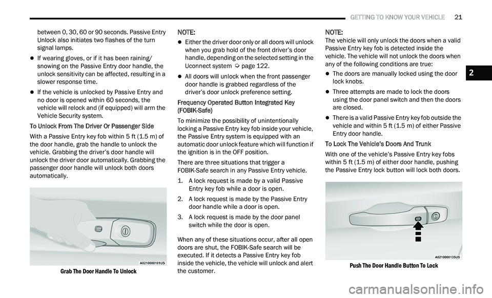
To Unlock From The Driver Or Passenger Side
With a Passive Entry key fob within 5 ft (1.5 m) of
t h
e door handle, grab the handle to unlock the
vehicle. Grabbing the driver’s door handle will
unlock the driver door automatically. Grabbing the
passenger door handle will unlock both doors
automatically.
Grab The Door Handle To Unlock
NOTE:
Either the driver door only or all doors will unlock
when you grab hold of the front driver’s door
handle, depending on the selected setting in the
Uconnect system
Ú page 122.
All doors will unlock when the front passenger
door handle is grabbed regardless of the
driver’s door unlock preference setting.
Frequency Operated Button Integrated Key
( F
OBIK-Safe)
To minimize the possibility of unintentionally
loc
king a Passive Entry key fob inside your vehicle,
the Passive Entry system is equipped with an
automatic door unlock feature which will function if
the ignition is in the OFF position.
There are three situations that trigger a
F O
BIK-Safe search in any Passive Entry vehicle.
1. A lock request is made by a valid Passive E
ntry key fob while a door is open.
2. A lock request is made by the Passive Entry d
oor handle while a door is open.
3. A lock request is made by the door panel s
witch while the door is open.
When any of these situations occur, after all open
door
s are shut, the FOBIK-Safe search will be
executed. If it detects a Passive Entry key fob
inside the vehicle, the vehicle will unlock and alert
the customer.
NOTE:
The vehicle will only unlock the doors when a valid
P a
ssive Entry key fob is detected inside the
vehicle. The vehicle will not unlock the doors when
any of the following conditions are true:
The doors are manually locked using the door
lock knobs.
Three attempts are made to lock the doors
using the door panel switch and then the doors
are closed.
There is a valid Passive Entry key fob outside the
vehicle and within 5 ft (1.5 m) of either Passive
E n
try door handle.
To Lock The Vehicle’s Doors And Trunk
With one of the vehicle’s Passive Entry key fobs
w i
thin 5 ft (1.5 m) of either door handle, pushing
t h
e Passive Entry lock button will lock both doors.
Push The Door Handle Button To Lock
2
Page 37 of 268
GETTING TO KNOW YOUR VEHICLE 35
OUTSIDE MIRRORS
The outside mirror(s) can be adjusted to the center
of the adjacent lane of traffic to achieve the
optimal view.
DRIVER'S OUTSIDE AUTOMATIC
D
IMMING MIRROR — IF EQUIPPED
The driver’s outside mirror will automatically adjust
for glare from vehicles behind you. This feature is
controlled by the inside automatic dimming mirror
and will automatically adjust for headlight glare
when the inside mirror adjusts.
OUTSIDE MIRRORS WITH TURN SIGNAL
A
ND APPROACH LIGHTING —
I
F EQUIPPED
Driver and passenger outside mirrors with turn
signal and approach lighting contain four LEDs,
which are located in the upper outer corner of each
mirror.
Three of the LEDs are turn signal indicators, which
fl
ash with the corresponding turn signal lights in
the front and rear of the vehicle. Turning on the
Hazard Warning flashers will also activate these
LEDs.
The fourth LED supplies illuminated entry lighting,
w h
ich turns on in both mirrors when you use the
key fob or open any door. This LED shines outward
to illuminate the front and rear door handles. It
also shines downward to illuminate the area in
front of the doors.
The illuminated entry lighting fades to off after
ab
out 30 seconds or it will fade to off immediately
once the ignition is placed into the ON/RUN
position.
NOTE:
The approach lighting will not function when the
g e
ar selector is moved out of the PARK position.
POWER MIRRORS
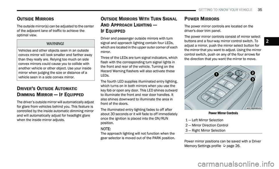
The power mirror controls are located on the
driver's door trim panel.
The power mirror controls consist of mirror select
bu
ttons and a four-way mirror control switch. To
adjust a mirror, push the mirror select button for
the mirror that you want to adjust. Using the mirror
control switch, push on any of the four arrows for
the direction that you want the mirror to move.
Power Mirror Controls
Power mirror positions can be saved with a Driver
M e
mory Settings profile Ú page 26.
WARNING!
Vehicles and other objects seen in an outside
convex mirror will look smaller and farther away
than they really are. Relying too much on side
convex mirrors could cause you to collide with
another vehicle or other object. Use your inside
mirror when judging the size or distance of a
vehicle seen in a side convex mirror.
1 — Left Mirror Selection
2 — Mirror Direction Control
3 — Right Mirror Selection
2
Page 43 of 268
GETTING TO KNOW YOUR VEHICLE 41
DAYTIME RUNNING LIGHTS (DRLS)
The Daytime Running Lights will turn on when the
engine is started and will remain on unless the
headlights are turned to the on position, the
parking brake is applied, or the ignition is placed in
the OFF position.
NOTE:
For vehicles sold in Canada, the Daytime
Running Lights will automatically deactivate
when the front fog lights are turned on.
If allowed by law in the country in which the
vehicle was purchased, the Daytime Running
Lights can be turned on and off using the
Uconnect system
Ú page 122.
On some vehicles, the Daytime Running Lights
may deactivate or reduce intensity on one side
of the vehicle (when a turn signal is activated on
that side), or on both sides of the vehicle (when
the hazard warning lights are activated).
HIGH/LOW BEAM SWITCH
Push the multifunction lever toward the instrument
panel to switch the headlights to high beams.
Pulling the multifunction lever back will turn the
low beams on.
AUTOMATIC HIGH BEAM — IF EQUIPPED
The Automatic High Beam Headlamp Control
system provides increased forward lighting at night
by automating high beam control through the use
of a digital camera mounted on the inside rearview
mirror. This camera detects vehicle specific light
and automatically switches from high beams to low
beams until the approaching vehicle is out of view.
NOTE:
The Automatic High Beam Headlamp Control
can be turned on or off by selecting or dese
-
lecting “Auto High Beam” within Uconnect
Se
ttings Ú page 122, as well as turning the
headlight switch to the AUTO position.
Broken, muddy, or obstructed headlights and
taillights of vehicles in the field of view will
cause headlights to remain on longer (closer to
the vehicle). Also, dirt, film, and other obstruc -
tions on the windshield or camera lens will
c a
use the system to function improperly.
If the windshield or Automatic High Beam Head -
lamp Control mirror is replaced, the mirror must
b e
re-aimed to ensure proper performance. See
a local authorized dealer.
FLASH-TO-PASS
You can signal another vehicle with your headlights
by lightly pulling the multifunction lever toward you. This will cause the high beam headlights to turn on,
and remain on, until the lever is released.
AUTOMATIC HEADLIGHTS
This system automatically turns the headlights on
or off according to ambient light levels. To turn the
system on, rotate the headlight switch
counterclockwise to the AUTO position. When the
system is on, the headlight time delay feature is
also on. This means the headlights will stay on for
up to 90 seconds after placing the ignition in the
OFF position. The headlight time delay can be
programmed 0/30/60/90 seconds within
Uconnect Settings
Ú page 122.
To turn the automatic system off, move the
h e
adlight switch out of the AUTO position.
NOTE:
The engine must be running before the headlights
w i
ll come on in the automatic mode.
PARKING LIGHTS
To turn on the parking lights and instrument panel
lights, rotate the headlight switch clockwise. To
turn off the parking lights, rotate the headlight
switch back to the O (off) position.
NOTE:
For vehicles sold in Canada, rotate the headlight
s w
itch to the AUTO position to turn off the parking
lights.
2
Page 45 of 268
GETTING TO KNOW YOUR VEHICLE 43
To activate the front fog lights, turn on the parking
lights or the low beam headlights and push the
headlight switch. To turn off the front fog lights,
either push the headlight switch a second time or
turn off the headlight switch.
NOTE:
The fog lights will operate with the low beam head -
lights or parking lights on. However, selecting the
h i
gh beam headlights will turn off the fog lights.
TURN SIGNALS
Move the multifunction lever up or down to
activate the turn signals. The arrows on each side
of the instrument cluster flash to show proper
operation.
NOTE:
If either light remains on and does not flash, or
there is a very fast flash rate, check for a defec -
tive outside light bulb.
A “Turn Signal On” message will appear in the
instrument cluster display and a continuous
chime will sound if the vehicle is driven more
than 1 mile (1.6 km) with either turn signal on.
LANE CHANGE ASSIST — IF EQUIPPED
Lightly push the multifunction lever up or down,
without moving beyond the detent, and the turn
signal will flash three times then automatically turn
off.
INTERIOR LIGHTS
The interior lights come on when a door is opened.
To protect the battery, the interior lights will turn off
au
tomatically 10 minutes after the ignition is
p l
aced in the OFF position. This will occur if the
interior lights were switched on manually or are on
because a door is open. The Battery Protection
also includes the glove compartment light and the
trunk light. To restore interior light operation after
automatic battery protection is enabled (lights off),
either place the ignition in the ON/RUN position, or
cycle the light switch.
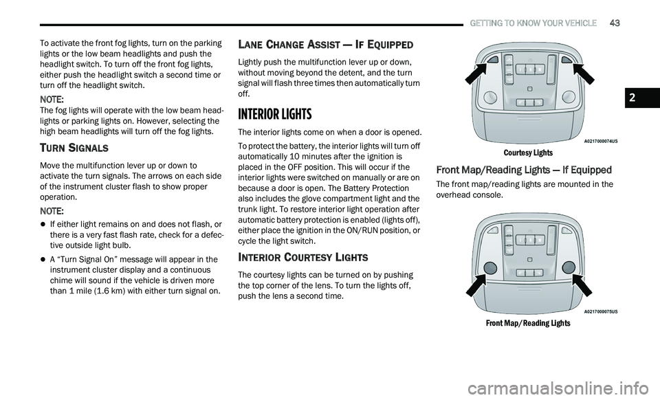
INTERIOR COURTESY LIGHTS
The courtesy lights can be turned on by pushing
the top corner of the lens. To turn the lights off,
push the lens a second time.
Courtesy Lights
Front Map/Reading Lights — If Equipped
The front map/reading lights are mounted in the
overhead console.
Front Map/Reading Lights
2
Page 73 of 268
GETTING TO KNOW YOUR INSTRUMENT PANEL 71
NOTE:
The charging system is independent from load
reduction. The charging system performs a diag
-
nostic on the charging system continuously.
If the Battery Charge Warning Light is on it may
indicate a problem with the charging system
Ú page 73.
The electrical loads that may be switched off (if
e q
uipped), and vehicle functions which can be
affected by load reduction:
Heated Seat/Vented Seats/Heated Wheel —
If Equipped
Heated/Cooled Cup Holders — If Equipped
Rear Defroster And Heated Mirrors
HVAC System
115 Volts AC Power Inverter System
Audio and Telematics System
Loss of the battery charge may indicate one or
m or
e of the following conditions:
The charging system cannot deliver enough
electrical power to the vehicle system because
the electrical loads are larger than the capability
of the charging system. The charging system is
still functioning properly.
Turning on all possible vehicle electrical loads
(e.g. HVAC to max settings, exterior and interior
lights, overloaded power outlets +12 Volts, 115 Volts AC, USB ports) during certain driving
c
on
ditions (city driving, towing, frequent stop -
ping).
Installing options like additional lights, upfitter
electrical accessories, audio systems, alarms
and similar devices.
Unusual driving cycles (short trips separated by
long parking periods).
The vehicle was parked for an extended period
of time (weeks, months).
The battery was recently replaced and was not
charged completely.
The battery was discharged by an electrical load
left on when the vehicle was parked.
The battery was used for an extended period
with the engine not running to supply radio,
lights, chargers, +12 Volt portable appliances
like vacuum cleaners, game consoles and
similar devices.
What to do when an electrical load reduction
a c
tion message is present (“Battery Saver On” or
“Battery Saver Mode”)
During a trip:
Reduce power to unnecessary loads if possible:
Turn off redundant lights (interior or exte -
rior)
Check what may be plugged in to power
outlets +12 Volts, 115 Volts AC, USB ports
Check HVAC settings (blower, temperature)
Check the audio settings (volume)
After a trip:
Check if any aftermarket equipment was
installed (additional lights, upfitter electrical
accessories, audio systems, alarms) and review
specifications if any (load and Ignition Off Draw
currents).
Evaluate the latest driving cycles (distance,
driving time and parking time).
The vehicle should have service performed if
the message is still present during consecutive
trips and the evaluation of the vehicle and
driving pattern did not help to identify the cause.
PROGRAMMABLE FEATURES
The instrument cluster display can be used to view
or change the following settings. Push the up
or
down arrow button to scroll through the main
menus, then push the ri
ght arrow button to
scroll through the submenus of each menu item.
P u
sh the left arrow button to scroll back to a
previous menu or submenu.
WARNING LIGHTS AND MESSAGES
The warning/indicator lights will illuminate in the
instrument panel together with a dedicated
message and/or acoustic signal when applicable.
These indications are indicative and precautionary
3