trailer CHRYSLER 300 2022 Owners Manual
[x] Cancel search | Manufacturer: CHRYSLER, Model Year: 2022, Model line: 300, Model: CHRYSLER 300 2022Pages: 288, PDF Size: 13.34 MB
Page 6 of 288
4
GETTING TO KNOW YOUR
INSTRUMENT PANEL
INSTRUMENT CLUSTER ........................................ 68
Instrument Cluster Descriptions ....................70
INSTRUMENT CLUSTER DISPLAY ........................ 70
Location And Controls ......................................71
Engine Oil Life Reset .......................................72
Instrument Cluster Display Selectable Menu
Items .................................................................73
Battery Saver On/Battery Saver Mode
Message — Electrical Load Reduction
Actions —If Equipped .......................................75
Programmable Features ..................................76
WARNING LIGHTS AND MESSAGES ................... 76
Red Warning Lights ..........................................77
Yellow Warning Lights ......................................79
Yellow Indicator Lights .....................................82
Green Indicator Lights......................................82
White Indicator Lights ......................................83
Blue Indicator Lights ........................................83
ONBOARD DIAGNOSTIC SYSTEM — OBD II ....... 84
Onboard Diagnostic System
(OBD II) Cybersecurity ......................................84
EMISSIONS INSPECTION AND MAINTENANCE
PROGRAMS ............................................................ 85
STARTING AND OPERATING
STARTING THE ENGINE ........................................86
Automatic Transmission .................................86
Keyless Enter ‘n Go™ — Ignition......................86
Normal Starting ...............................................86
AutoPark ...........................................................87
Extended Park Starting ....................................88
If Engine Fails To Start .....................................88
Cold Weather Operation
(Below –22°F Or −30°C) ...............................89
After Starting ....................................................89
ENGINE BLOCK HEATER — IF EQUIPPED ...........89
ENGINE BREAK-IN RECOMMENDATIONS ...........89
PARKING BRAKE ....................................................90
AUTOMATIC TRANSMISSION ................................91
Ignition Park Interlock ......................................92
Brake Transmission Shift Interlock (BTSI)
System ..............................................................92
8-Speed Automatic Transmission ...................92
SPORT MODE — IF EQUIPPED ..............................97
FUEL SAVER TECHNOLOGY 5.7L ONLY —
IF EQUIPPED ...........................................................97
POWER STEERING .................................................97
CRUISE CONTROL SYSTEMS — IF EQUIPPED ....98 Cruise Control ..................................................98
Adaptive Cruise Control (ACC) ...................... 100 PARKSENSE FRONT AND REAR PARK
ASSIST — IF EQUIPPED ....................................... 108
ParkSense Sensors ....................................... 109
ParkSense Display ........................................ 109
ParkSense Warning Display ......................... 112
Enabling And Disabling ParkSense.............. 112
Service The ParkSense Park Assist System ...112
Cleaning The ParkSense System ................. 113
ParkSense System Usage Precautions........ 113
LANESENSE — IF EQUIPPED ............................. 114
LaneSense Operation ................................... 114
Turning LaneSense On Or Off....................... 114
LaneSense Warning Message...................... 115
Changing LaneSense Status ........................ 116
PARKVIEW REAR BACK UP CAMERA ............... 116
REFUELING THE VEHICLE ................................... 118 Emergency Fuel Filler Door Release ............ 118
VEHICLE LOADING .............................................. 119
Vehicle Certification Label............................ 119
Gross Vehicle Weight Rating (GVWR) .......... 119
Gross Axle Weight Rating (GAWR) ............... 119
Overloading ................................................... 119
Loading ......................................................... 120
TRAILER TOWING ................................................ 120
Common Towing Definitions......................... 120
Trailer Hitch Classification............................ 122
Trailer Towing Weights (Maximum Trailer
Weight Ratings) ............................................ 122
Trailer And Tongue Weight .......................... 123
Towing Requirements ................................... 123
Towing Tips ................................................... 125
22_LX_OM_EN_USC_t.book Page 4
Page 72 of 288
70GETTING TO KNOW YOUR INSTRUMENT PANEL
INSTRUMENT CLUSTER DESCRIPTIONS
1. Tachometer
Indicates the engine speed in revolutions
per minute (RPM x 1000).
2. Instrument Cluster Display
When the appropriate conditions exist, this
display shows the instrument cluster
display messages Ú page 70.
3. Speedometer
Indicates vehicle speed.
4. Temperature Gauge
The temperature gauge shows engine
coolant temperature. Any reading within the
normal range indicates that the engine
cooling system is operating satisfactorily.
The gauge pointer will likely indicate a
higher temperature when driving in hot
weather, up mountain grades, or when
towing a trailer. It should not be allowed to
exceed the upper limits of the normal oper -
ating range. 5. Fuel Gauge
The pointer shows the level of fuel in the
fuel tank when the Keyless Push Button
Ignition is in the ON/RUN position.
The fuel pump symbol points to
the side of the vehicle where the
fuel door is located.
NOTE:The warning / indicator Lights will briefly illuminate
for a bulb check when the ignition is first cycled.
INSTRUMENT CLUSTER DISPLAY
Your vehicle is equipped with an instrument cluster
display, which offers useful information to the
driver. With the ignition in the OFF mode, opening/
closing of a door will activate the display for
viewing, and display the total miles, or kilometers,
in the odometer. Your instrument cluster display is
designed to display important information about
your vehicle’s systems and features. Using a driver
interactive display located on the instrument
panel, your instrument cluster display can show
you how systems are working and give you
warnings when they are not. The steering wheel
mounted controls allow you to scroll through the
main menus and submenus. You can access the
specific information you want and make selections
and adjustments.
WARNING!
A hot engine cooling system is dangerous. You or
others could be badly burned by steam or boiling
coolant. It is recommended to call an authorized
dealer for service if your vehicle overheats
Ú page 224.
CAUTION!
Driving with a hot engine cooling system could
damage your vehicle. If the temperature gauge
reads “H,” pull over and stop the vehicle. Idle the
vehicle with the air conditioner turned off until
the pointer drops back into the normal range. If
the pointer remains on the “H,” turn the engine
off immediately and call an authorized dealer for
service.
22_LX_OM_EN_USC_t.book Page 70
Page 81 of 288
GETTING TO KNOW YOUR INSTRUMENT PANEL79
Trunk Open Warning Light
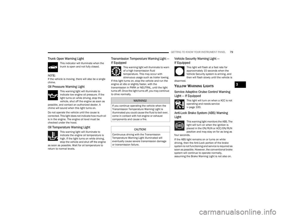
This indicator will illuminate when the
trunk is open and not fully closed.
NOTE:If the vehicle is moving, there will also be a single
chime.
Oil Pressure Warning Light
This warning light will illuminate to
indicate low engine oil pressure. If the
light turns on while driving, stop the
vehicle, shut off the engine as soon as
possible, and contact an authorized dealer. A
chime will sound when this light turns on.
Do not operate the vehicle until the cause is
corrected. This light does not indicate how much oil
is in the engine. The engine oil level must be
checked under the hood.
Oil Temperature Warning Light
This warning light will illuminate to
indicate the engine oil temperature is
high. If the light turns on while driving,
stop the vehicle and shut off the engine
as soon as possible. Wait for oil temperature to
return to normal levels.
Transmission Temperature Warning Light —
If Equipped
This warning light will illuminate to warn
of a high transmission fluid
temperature. This may occur with
strenuous usage such as trailer towing.
If this light turns on, stop the vehicle and run the
engine at idle or slightly faster, with the
transmission in PARK or NEUTRAL, until the light
turns off. Once the light turns off, you may continue
to drive normally.
Vehicle Security Warning Light —
If Equipped
This light will flash at a fast rate for
approximately 15 seconds when the
Vehicle Security system is arming, and
then will flash slowly until the vehicle is
disarmed.
YELLOW WARNING LIGHTS
Service Adaptive Cruise Control Warning
Light — If Equipped
This light will turn on when a ACC is not
operating and needs service
Ú page 100.
Anti-Lock Brake System (ABS) Warning
Light
This warning light monitors the ABS. The
light will turn on when the ignition is
placed in the ON/RUN or ACC/ON/RUN
position and may stay on for as long as
four seconds.
If the ABS light remains on or turns on while
driving, then the Anti-Lock portion of the brake
system is not functioning and service is required as
soon as possible. However, the conventional brake
system will continue to operate normally,
assuming the Brake Warning Light is not also on.
WARNING!
If you continue operating the vehicle when the
Transmission Temperature Warning Light is
illuminated you could cause the fluid to boil over,
come in contact with hot engine or exhaust
components and cause a fire.
CAUTION!
Continuous driving with the Transmission
Temperature Warning Light illuminated will
eventually cause severe transmission damage
or transmission failure.
3
22_LX_OM_EN_USC_t.book Page 79
Page 97 of 288
STARTING AND OPERATING95
DRIVE (D)
This range should be used for most city and
highway driving. It provides the smoothest upshifts
and downshifts, and the best fuel economy. The
transmission automatically upshifts through all
forward gears. The DRIVE position provides
optimum driving characteristics under all normal
operating conditions.
When frequent transmission shifting occurs (such
as when operating the vehicle under heavy loading
conditions, in hilly terrain, traveling into strong
head winds, or while towing a heavy trailer), use
the AutoStick shift control (if equipped) to select a
lower gear Úpage 96. Under these conditions,
using a lower gear will improve performance and
extend transmission life by reducing excessive
shifting and heat buildup. During extremely cold temperatures (-22°F
[-30°C] or below), transmission operation may be
modified depending on engine and transmission
temperature as well as vehicle speed. Normal
operation will resume once the transmission
temperature has risen to a suitable level.
SPORT (S) — IF EQUIPPED
This mode alters the transmission's automatic
shift schedule for sportier driving. Upshift speeds
are increased to make full use of available engine
power.
To access SPORT mode, push down on the gear
selector and rotate it fully clockwise, or push the
SPORT button in the center stack.
LOW (L) — IF EQUIPPED
Use this range for engine braking when
descending very steep grades. In this range, the
transmission will downshift for increased engine
braking. To access the LOW position, push down
on the gear selector and rotate it fully clockwise.
Transmission Limp Home Mode
Transmission function is monitored electronically
for abnormal conditions. If a condition is detected
that could result in transmission damage,
Transmission Limp Home Mode is activated. In this
mode, the transmission may operate only in
certain gears, or may not shift at all. Vehicle
performance may be severely degraded and the engine may stall. In some situations, the
transmission may not re-engage if the engine is
turned off and restarted. The Malfunction Indicator
Light (MIL) may be illuminated. A message in the
instrument cluster will inform the driver of the
more serious conditions, and indicate what actions
may be necessary.
In the event of a momentary problem, the
transmission can be reset to regain all forward
gears by performing the following steps:
NOTE:In cases where the instrument cluster message
indicates the transmission may not re-engage after
engine shutdown, perform this procedure only in a
desired location (preferably, at an authorized
dealer).
1. Stop the vehicle.
2. Shift the transmission into PARK, if possible. If
not, shift the transmission to NEUTRAL.
3. Push and hold the ignition switch until the engine turns off.
4. Wait approximately 30 seconds.
5. Restart the engine.
6. Shift into the desired gear range. If the problem is no longer detected, the
transmission will return to normal operation.
CAUTION!
Towing the vehicle, coasting, or driving for any
other reason with the transmission in NEUTRAL
can cause severe transmission damage.
For “Recreational Towing” Ú page 126
For “Towing A Disabled Vehicle” Ú page 208
4
22_LX_OM_EN_USC_t.book Page 95
Page 98 of 288
96STARTING AND OPERATING
NOTE:Even if the transmission can be reset, we
recommend that you visit an authorized dealer at
your earliest possible convenience. An authorized
dealer has diagnostic equipment to assess the
condition of your transmission.
If the transmission cannot be reset, authorized
dealer service is required.
AutoStick — If Equipped
AutoStick is a driver-interactive transmission
feature providing manual shift control, giving you
more control of the vehicle. AutoStick allows you to
maximize engine braking, eliminate undesirable
upshifts and downshifts, and improve overall
vehicle performance.
This system can also provide you with more control
during passing, city driving, cold slippery
conditions, mountain driving, trailer towing, and
many other situations.
Operation
When the transmission is in DRIVE or SPORT
mode, it will operate automatically, shifting
between the eight available gears. To engage
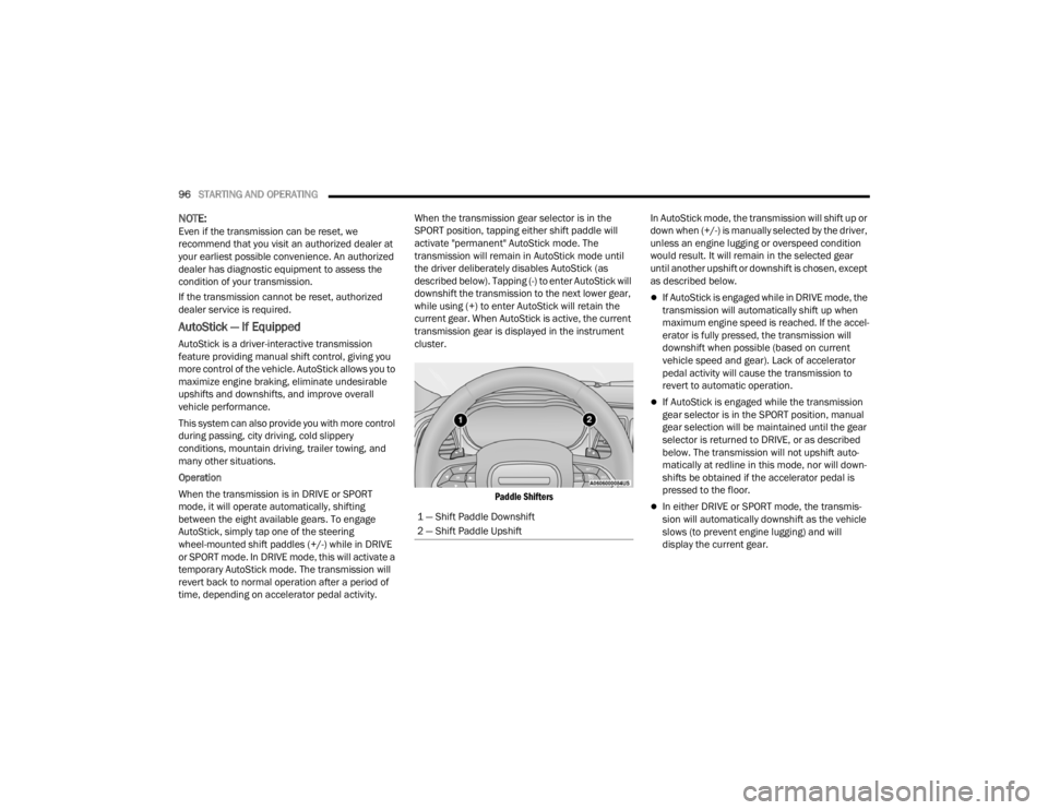
AutoStick, simply tap one of the steering
wheel-mounted shift paddles (+/-) while in DRIVE
or SPORT mode. In DRIVE mode, this will activate a
temporary AutoStick mode. The transmission will
revert back to normal operation after a period of
time, depending on accelerator pedal activity. When the transmission gear selector is in the
SPORT position, tapping either shift paddle will
activate "permanent" AutoStick mode. The
transmission will remain in AutoStick mode until
the driver deliberately disables AutoStick (as
described below). Tapping (-) to enter AutoStick will
downshift the transmission to the next lower gear,
while using (+) to enter AutoStick will retain the
current gear. When AutoStick is active, the current
transmission gear is displayed in the instrument
cluster.
Paddle Shifters
In AutoStick mode, the transmission will shift up or
down when (+/-) is manually selected by the driver,
unless an engine lugging or overspeed condition
would result. It will remain in the selected gear
until another upshift or downshift is chosen, except
as described below.
If AutoStick is engaged while in DRIVE mode, the
transmission will automatically shift up when
maximum engine speed is reached. If the accel
-
erator is fully pressed, the transmission will
downshift when possible (based on current
vehicle speed and gear). Lack of accelerator
pedal activity will cause the transmission to
revert to automatic operation.
If AutoStick is engaged while the transmission
gear selector is in the SPORT position, manual
gear selection will be maintained until the gear
selector is returned to DRIVE, or as described
below. The transmission will not upshift auto -
matically at redline in this mode, nor will down -
shifts be obtained if the accelerator pedal is
pressed to the floor.
In either DRIVE or SPORT mode, the transmis -
sion will automatically downshift as the vehicle
slows (to prevent engine lugging) and will
display the current gear.
1 — Shift Paddle Downshift
2 — Shift Paddle Upshift
22_LX_OM_EN_USC_t.book Page 96
Page 103 of 288
STARTING AND OPERATING101
Adaptive Cruise Control (ACC) Operation
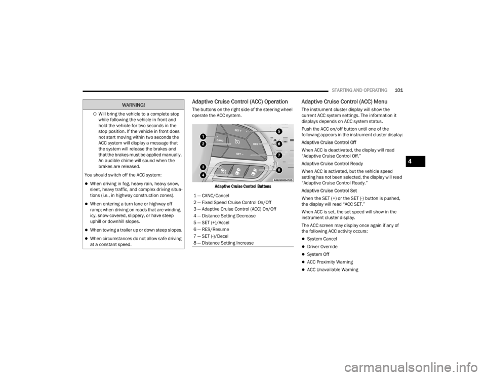
The buttons on the right side of the steering wheel
operate the ACC system.
Adaptive Cruise Control Buttons
Adaptive Cruise Control (ACC) Menu
The instrument cluster display will show the
current ACC system settings. The information it
displays depends on ACC system status.
Push the ACC on/off button until one of the
following appears in the instrument cluster display:
Adaptive Cruise Control Off
When ACC is deactivated, the display will read
“Adaptive Cruise Control Off.”
Adaptive Cruise Control Ready
When ACC is activated, but the vehicle speed
setting has not been selected, the display will read
“Adaptive Cruise Control Ready.”
Adaptive Cruise Control Set
When the SET (+) or the SET (-) button is pushed,
the display will read “ACC SET.”
When ACC is set, the set speed will show in the
instrument cluster display.
The ACC screen may display once again if any of
the following ACC activity occurs:
System Cancel
Driver Override
System Off
ACC Proximity Warning
ACC Unavailable Warning
Will bring the vehicle to a complete stop
while following the vehicle in front and
hold the vehicle for two seconds in the
stop position. If the vehicle in front does
not start moving within two seconds the
ACC system will display a message that
the system will release the brakes and
that the brakes must be applied manually.
An audible chime will sound when the
brakes are released.
You should switch off the ACC system:
When driving in fog, heavy rain, heavy snow,
sleet, heavy traffic, and complex driving situa -
tions (i.e., in highway construction zones).
When entering a turn lane or highway off
ramp; when driving on roads that are winding,
icy, snow-covered, slippery, or have steep
uphill or downhill slopes.
When towing a trailer up or down steep slopes.
When circumstances do not allow safe driving
at a constant speed.
WARNING!
1 — CANC/Cancel
2 — Fixed Speed Cruise Control On/Off
3 — Adaptive Cruise Control (ACC) On/Off
4 — Distance Setting Decrease
5 — SET (+)/Accel
6 — RES/Resume
7 — SET (-)/Decel
8 — Distance Setting Increase
4
22_LX_OM_EN_USC_t.book Page 101
Page 109 of 288
STARTING AND OPERATING107
When the condition that created limited
functionality is no longer present, the system will
return to full functionality.
NOTE:If the “ACC/FCW Limited Functionality Clean Front
Windshield” message occurs frequently (e.g. more
than once on every trip) without any snow, rain,
mud, or other obstruction, have the windshield and
forward facing camera inspected at an authorized
dealer.
SERVICE ACC/FCW WARNING
If the system turns off, and the instrument cluster
displays “ACC/FCW Unavailable Service Required”
or “Cruise/FCW Unavailable Service Required”,
there may be an internal system fault or a
temporary malfunction that limits ACC
functionality. Although the vehicle is still drivable
under normal conditions, ACC will be temporarily
unavailable. If this occurs, try activating ACC again
later, following an ignition cycle. If the problem
persists, see an authorized dealer.
Precautions While Driving With ACC
In certain driving situations, ACC may have
detection issues. In these cases, ACC may brake
late or unexpectedly. The driver needs to stay alert
and may need to intervene. The following are
examples of these types of situations:
TOWING A TRAILER
Towing a trailer is not recommended when using
ACC.
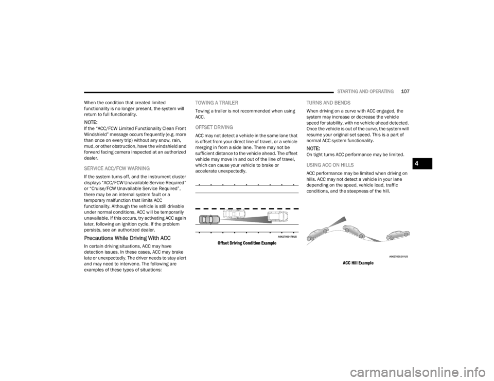
OFFSET DRIVING
ACC may not detect a vehicle in the same lane that
is offset from your direct line of travel, or a vehicle
merging in from a side lane. There may not be
sufficient distance to the vehicle ahead. The offset
vehicle may move in and out of the line of travel,
which can cause your vehicle to brake or
accelerate unexpectedly.
Offset Driving Condition Example
TURNS AND BENDS
When driving on a curve with ACC engaged, the
system may increase or decrease the vehicle
speed for stability, with no vehicle ahead detected.
Once the vehicle is out of the curve, the system will
resume your original set speed. This is a part of
normal ACC system functionality.
NOTE:On tight turns ACC performance may be limited.
USING ACC ON HILLS
ACC performance may be limited when driving on
hills. ACC may not detect a vehicle in your lane
depending on the speed, vehicle load, traffic
conditions, and the steepness of the hill.
ACC Hill Example
4
22_LX_OM_EN_USC_t.book Page 107
Page 115 of 288
STARTING AND OPERATING113
If the "PARKSENSE UNAVAILABLE SERVICE
REQUIRED" message appears in the instrument
cluster display, see an authorized dealer.
CLEANING THE PARKSENSE SYSTEM
Clean the ParkSense sensors with water, car wash
soap and a soft cloth. Do not use rough or hard
cloths. Do not scratch or poke the sensors.
Otherwise, you could damage the sensors.
PARKSENSE SYSTEM USAGE
P
RECAUTIONS
NOTE:
Ensure that the front and rear bumpers are free
of snow, ice, mud, dirt and debris to keep the
ParkSense system operating properly.
Jackhammers, large trucks, and other vibra -
tions could affect the performance of
ParkSense.
When you turn ParkSense off, the instrument
cluster will display “PARKSENSE OFF.” Once you
turn ParkSense off, it remains off until you turn
it on again, even if you cycle the ignition.
When you move the gear selector to the
REVERSE position and ParkSense is turned off,
the instrument cluster will display “PARKSENSE
OFF” for as long as the vehicle is in REVERSE.
ParkSense, when on, will reduce the volume of
the radio when it is sounding a tone.
Clean the ParkSense sensors regularly, taking
care not to scratch or damage them. The
sensors must not be covered with ice, snow,
slush, mud, dirt or debris. Failure to do so can
result in the system not working properly. The
ParkSense system might not detect an obstacle
behind or in front of the fascia/bumper, or it
could provide a false indication that an obstacle
is behind or in front of the fascia/bumper.
Use the ParkSense switch to turn the ParkSense
system off if objects such as bicycle carriers,
trailer hitches, etc., are placed within 12 inches
(30 cm) from the rear fascia/bumper. Failure to
do so can result in the system misinterpreting a
close object as a sensor problem, causing the
“PARKSENSE UNAVAILABLE SERVICE
REQUIRED” message to be displayed in the
instrument cluster.
WARNING!
Drivers must be careful when backing up even
when using ParkSense. Always check carefully
behind your vehicle, look behind you, and be
sure to check for pedestrians, animals, other
vehicles, obstructions, and blind spots before
backing up. You are responsible for safety and
must continue to pay attention to your
surroundings. Failure to do so can result in
serious injury or death.
Before using ParkSense, it is strongly recom -
mended that the ball mount and hitch ball
assembly be disconnected from the vehicle
when the vehicle is not used for towing.
Failure to do so can result in injury or damage
to vehicles or obstacles because the hitch ball
will be much closer to the obstacle than the
rear fascia/bumper when the vehicle sounds
the continuous tone. Also, the sensors could
detect the ball mount and hitch ball assembly,
depending on its size and shape, giving a false
indication that an obstacle is behind the
vehicle.
4
22_LX_OM_EN_USC_t.book Page 113
Page 122 of 288
120STARTING AND OPERATING
The best way to figure out the total weight of your
vehicle is to weigh it when it is fully loaded and
ready for operation. Weigh it on a commercial scale
to ensure that it is not over the GVWR.
Figure out the weight on the front and rear of the
vehicle separately. It is important that you
distribute the load evenly over the front and rear
axles.
Overloading can cause potential safety hazards
and shorten useful service life. Heavier axles or
suspension components do not necessarily
increase the vehicle's GVWR.
LOADING
To load your vehicle properly, first figure out its
empty weight, axle-by-axle and side-by-side. Store
heavier items down low and be sure you distribute
their weight as evenly as possible. Stow all loose
items securely before driving. If weighing the
loaded vehicle shows that you have exceeded
either GAWR, but the total load is within the
specified GVWR, you must redistribute the weight.
Improper weight distribution can have an adverse
effect on the way your vehicle steers and handles
and the way the brakes operate.
NOTE:
Refer to the “Vehicle Certification Label” affixed
to the rear of the driver's door for your vehicle's
GVWR and GAWRs Ú page 119.
Refer to the “Tire Placard” for your vehicle's
proper tire pressure.
TRAILER TOWING
In this section you will find safety tips and
information on limits to the type of towing you can
reasonably do with your vehicle. Before towing a
trailer, carefully review this information to tow your
load as efficiently and safely as possible.
To maintain the New Vehicle Limited Warranty
coverage, follow the requirements and
recommendations in this manual concerning
vehicles used for trailer towing.
COMMON TOWING DEFINITIONS
The following trailer towing related definitions will
assist you in understanding the following
information:
Gross Vehicle Weight Rating (GVWR)
The GVWR is the total allowable weight of your
vehicle. This includes driver, passengers, cargo
and tongue weight. The total load must be limited
so that you do not exceed the GVWR Ú page 120.
Gross Trailer Weight (GTW)
The GTW is the weight of the trailer plus the weight
of all cargo, consumables, and equipment
(permanent or temporary) loaded in or on the
trailer in its "loaded and ready for operation"
condition.
The recommended way to measure GTW is to put
your fully loaded trailer on a vehicle scale. The
entire weight of the trailer must be supported by
the scale.
22_LX_OM_EN_USC_t.book Page 120
Page 123 of 288
STARTING AND OPERATING121
Gross Combination Weight Rating (GCWR)
The GCWR is the total allowable weight of your
vehicle and trailer when weighed in combination.
Gross Axle Weight Rating (GAWR)
The GAWR is the maximum capacity of the front
and rear axles. Distribute the load over the front
and rear axles evenly. Make sure that you do not
exceed either front or rear GAWR Ú page 120.
Tongue Weight (TW)
The tongue weight is the downward force exerted
on the hitch ball by the trailer. You must consider
this as part of the load on your vehicle.
Trailer Frontal Area
The frontal area is the maximum height multiplied
by the maximum width of the front of a trailer.
Trailer Sway Control
The Trailer Sway Control (TSC) can be a mechanical
telescoping link that can be installed between the
hitch receiver and the trailer tongue that typically
provides adjustable friction associated with the
telescoping motion to dampen any unwanted
trailer swaying motions while traveling.
If equipped, the electronic TSC recognizes a
swaying trailer and automatically applies individual
wheel brakes and/or reduces engine power to
attempt to eliminate the trailer sway.
Weight-Carrying Hitch
A weight-carrying hitch supports the trailer tongue
weight, just as if it were luggage located at a hitch
ball or some other connecting point of the vehicle.
These kinds of hitches are the most popular on the
market today and they are commonly used to tow
small and medium sized trailers.
Weight-Distributing Hitch
A weight-distributing system works by applying
leverage through spring (load) bars. They are
typically used for heavier loads to distribute trailer
tongue weight to the tow vehicle's front axle and
the trailer axle(s). When used in accordance with
the manufacturer's directions, it provides for a
more level ride, offering more consistent steering
and brake control thereby enhancing towing
safety. The addition of a friction/hydraulic sway
control also dampens sway caused by traffic and
crosswinds and contributes positively to tow
vehicle and trailer stability. Trailer sway control and
a weight distributing (load equalizing) hitch are
recommended for heavier Tongue Weights (TW)
and may be required depending on vehicle and
trailer configuration/loading to comply with Gross
Axle Weight Rating (GAWR) requirements.
WARNING!
It is important that you do not exceed the
maximum front or rear GAWR. A dangerous
driving condition can result if either rating is
exceeded. You could lose control of the vehicle
and have a collision.
WARNING!
An improperly adjusted Weight Distributing
Hitch system may reduce handling, stability,
braking performance, and could result in a
collision.
Weight Distributing Systems may not be
compatible with Surge Brake Couplers.
Consult with your hitch and trailer manufac-
turer or a reputable Recreational Vehicle
dealer for additional information.
4
22_LX_OM_EN_USC_t.book Page 121