service indicator CHRYSLER 300 SRT 2009 1.G Owners Manual
[x] Cancel search | Manufacturer: CHRYSLER, Model Year: 2009, Model line: 300 SRT, Model: CHRYSLER 300 SRT 2009 1.GPages: 493, PDF Size: 7.53 MB
Page 80 of 493
Defroster
Check operation by selecting the defrost mode and place
the blower control on high speed. You should be able to
feel the air directed against the windshield. See your
authorized dealer for service if your defroster is
inoperable.
Periodic Safety Checks You Should Make Outside
The Vehicle
Tires
Examine tires for excessive tread wear and uneven wear
patterns. Check for stones, nails, glass, or other objects
lodged in the tread. Inspect the tread and sidewall for
cuts and cracks. Check the wheel nuts for tightness.
Check the tires (including spare) for proper pressure.
Lights
Have someone observe the operation of exterior lights
while you work the controls. Check turn signal and high
beam indicator lights on the instrument panel.
Door Latches
Check for positive closing, latching, and locking.
Fluid Leaks
Check area under vehicle after overnight parking for fuel,
engine coolant, oil, or other fluid leaks. Also, if gasoline
fumes are detected or if fuel, power steering fluid, or
brake fluid leaks are suspected, the cause should be
located and corrected immediately.
78 THINGS TO KNOW BEFORE STARTING YOUR VEHICLE
Page 141 of 493
Turn Signals
Move the multifunction lever up or down and the
corresponding turn signal indicator in the instrument
cluster flashes to show proper operation of the front and
rear turn signal lights. You can also signal a lane change
by moving the lever partially up or down without
moving beyond the detent. Releasing the lever at the
detent will provide three flashes.
If either indicator has a very fast flash rate, check for a
defective outside light bulb. If an indicator fails to light
when the lever is moved, see your authorized dealer for
service.
NOTE:A “Turn Signal On” message will appear in the
EVIC and a continuous chime will sound if the vehicle is
driven more than 1 mile (1.6 km) with either turn signal
on.
High Beam/Low Beam Select Switch
Push the multifunction lever away from you to switch
the headlights to high beam. Pull the multifunction lever
toward you to switch the headlights back to low beam.
Flash-To-Pass
You can signal another vehicle with your headlights by
lightly pulling the multifunction lever toward you. This
will cause the headlights to turn on at high beam and
remain on until the multifunction lever is released.
UNDERSTANDING THE FEATURES OF YOUR VEHICLE 139
3
Page 208 of 493
ODOMETER button to turn off the message. If the
problem continues, the message will appear the next time
the vehicle is started.
A loose, improperly installed, or damaged fuel filler cap
may also turn on the Malfunction Indicator Light (MIL).
7. Tachometer
The red segments indicate the maximum permissible
engine revolutions per minute (RPM x 1000) for each gear
range. Ease up on the accelerator before reaching the red
area.
8. Engine Temperature Warning Light
This light will turn on and a single chime will
sound to warn of an overheated engine condition.
When this light turns on, the engine temperature
is critically hot. The vehicle should be turned OFF
immediately and serviced as soon as possible.9. Anti-Lock Brake (ABS) Light
This light monitors the Anti-Lock Brake System
(ABS). The light will turn on when the ignition
switch is turned to the ON position and may stay on for
as long as four seconds.
If the ABS light remains on or turns on while driving,
then the Anti-Lock portion of the brake system is not
functioning and service is required. However, the con-
ventional brake system will continue to operate normally
if the BRAKE warning light is not on.
If the ABS light is on, the brake system should be serviced
as soon as possible to restore the benefits of Anti-Lock
brakes. If the ABS light does not turn on when the
ignition switch is turned to the ON position, have the
light inspected by an authorized dealer.
206 UNDERSTANDING YOUR INSTRUMENT PANEL
Page 211 of 493
The light also will turn on when the parking brake is
applied with the ignition switch in the ON position.
NOTE:This light shows only that the parking brake is
applied. It does not show the degree of brake application.
13. Electronic Stability Program (ESP) / Traction
Control System (TCS) Indicator Light
If this indicator light flashes during accelera-
tion, ease up on the accelerator and apply as
little throttle as possible. Adapt your speed and
driving to the prevailing road conditions, and
do not switch off the Electronic Stability Program (ESP).
14. Temperature Gauge
The temperature gauge shows engine coolant tempera-
ture. Any reading within the normal range indicates that
the engine cooling system is operating satisfactorily.The gauge pointer will likely indicate a higher tempera-
ture when driving in hot weather, up mountain grades,
or when towing a trailer. It should not be allowed to
exceed the upper limits of the normal operating range.
CAUTION!
Driving with a hot cooling system could damage
your vehicle. If the temperature gauge reads 240°F
(116°C) or greater, pull over and stop the vehicle. Idle
the vehicle with the air conditioner turned off until
the pointer drops back into the normal range 200–
230°F (93–110°C). If the pointer remains at 240°F
(116°C) or greater and you hear a chime, turn the
engine OFF immediately, and call for service.
UNDERSTANDING YOUR INSTRUMENT PANEL 209
4
Page 212 of 493
WARNING!
A hot engine cooling system is dangerous. You or
others could be badly burned by steam or boiling
coolant. You may want to call a service center if your
vehicle overheats. If you decide to look under the
hood yourself, refer to Section 7 and follow the
warnings under the Cooling System Pressure Cap
paragraph.
15. Trip Odometer Button
Press this button to change the display from odometer to
either of two trip odometer settings. The letter “A” or “B”
will appear when in the trip odometer mode. Push in and
hold the button for two seconds to reset the trip odometer
to 0 miles (km). The odometer must be in TRIP mode to
reset it.16. High Beam Light
This light will turn on when the high beam
headlights are ON. Push the multifunction lever
away from the steering wheel to switch the headlights to
high beam.
17. Shift Lever Indicator
This display indicator shows the automatic transmission
shift lever selection.
18. Seat Belt Reminder Light
This light will turn on for five to eight seconds as
a bulb check when the ignition switch is first
turned ON. A chime will sound if the driver’s seat
belt is unbuckled during the bulb check. The Seat Belt
Warning Light will flash, or remain on continuously, if
the driver’s seat belt remains unbuckled after the bulb
check or when driving.
210 UNDERSTANDING YOUR INSTRUMENT PANEL
Page 215 of 493
CAUTION!
The TPMS has been optimized for the original
equipment tires and wheels. TPMS pressures and
warning have been established for the tire size
equipped on your vehicle. Undesirable system opera-
tion or sensor damage may result when using re-
placement equipment that is not of the same size,
type, and/or style. Aftermarket wheels can cause
sensor damage. Do not use tire sealant from a can, or
balance beads if your vehicle is equipped with a
TPMS, as damage to the sensors may result.
23. Charging System Light
This light shows the status of the electrical charg-
ing system. The light should come on when the
ignition switch is first turned ON and remain on briefly
as a bulb check. If the light stays on or comes on while
driving, turn off some of the vehicle’s non-essential
electrical devices or increase engine speed (if at idle). Ifthe charging system light remains on, it means that the
vehicle is experiencing a problem with the charging
system. Obtain SERVICE IMMEDIATELY. See an autho-
rized dealer.
24. Malfunction Indicator Light (MIL)
The Malfunction Indicator Light (MIL) is part of
an onboard diagnostic system called OBD. The
OBD system monitors engine and automatic
transmission control systems. The MIL will turn on when
the key is in the ON position before engine start. If the
MIL does not come on when turning the key from LOCK
to ON, have the condition checked promptly.
Certain conditions such as a loose or missing gas cap,
poor fuel quality, etc., may illuminate the MIL after
engine start. The vehicle should be serviced if the MIL
stays on through several of your typical driving cycles. In
most situations, the vehicle will drive normally and will
not require towing.
UNDERSTANDING YOUR INSTRUMENT PANEL 213
4
Page 322 of 493
Delayed Shifts in Cold Temperatures
During cold temperature operation, you may notice
delayed upshifts depending on engine and transmission
temperature as well as vehicle speed. This feature im-
proves warm up time of the engine and transmission to
achieve maximum efficiency.
Temporary Transmission Limp Home Mode
The transmission is monitored for abnormal conditions.
If a condition is detected that could result in transmission
damage, the transmission will engage Limp Home Mode.
If vehicle acceleration worsens, or the transmission no
longer shifts, the transmission is most likely operating in
the Limp Home Mode. In this mode, the transmission
will remain in the current gear until the vehicle is
brought to a stop. After the vehicle has stopped, PARK,
REVERSE, and NEUTRAL will continue to operate. Sec-
ond gear will operate in the DRIVE position. The Mal-
function Indicator Light (MIL) may be illuminated.A reset feature is available to allow the vehicle to be
driven to an authorized dealer for service. To reset the
transmission, use the following procedure:
1. Stop the vehicle.
2. Move the shift lever to the PARK position.
3. Turn OFF the engine.
4. Wait approximately 10 seconds.
5. Restart the engine.
6. Move the shift lever to the desired range. If the
problem is no longer detected, the transmission will
return to normal operation.
NOTE:Even if the transmission can be reset, we recom-
mend that you visit your authorized dealer at your
earliest possible convenience. Your authorized dealer has
diagnostic equipment to determine if the problem could
recur.
320 STARTING AND OPERATING
Page 340 of 493
NOTE:
•The ESP/TCS Indicator Light and the ESP/BAS Mal-
function Indicator Light will turn on momentarily
each time the ignition switch is turned ON.
•Each time the ignition is turned ON, the ESP System
will be ON even if it was turned OFF previously.
•The ESP Control System will make buzzing or clicking
sounds when it is active. This is normal; the sounds
will stop when the ESP becomes inactive following the
maneuver that caused the ESP activation.
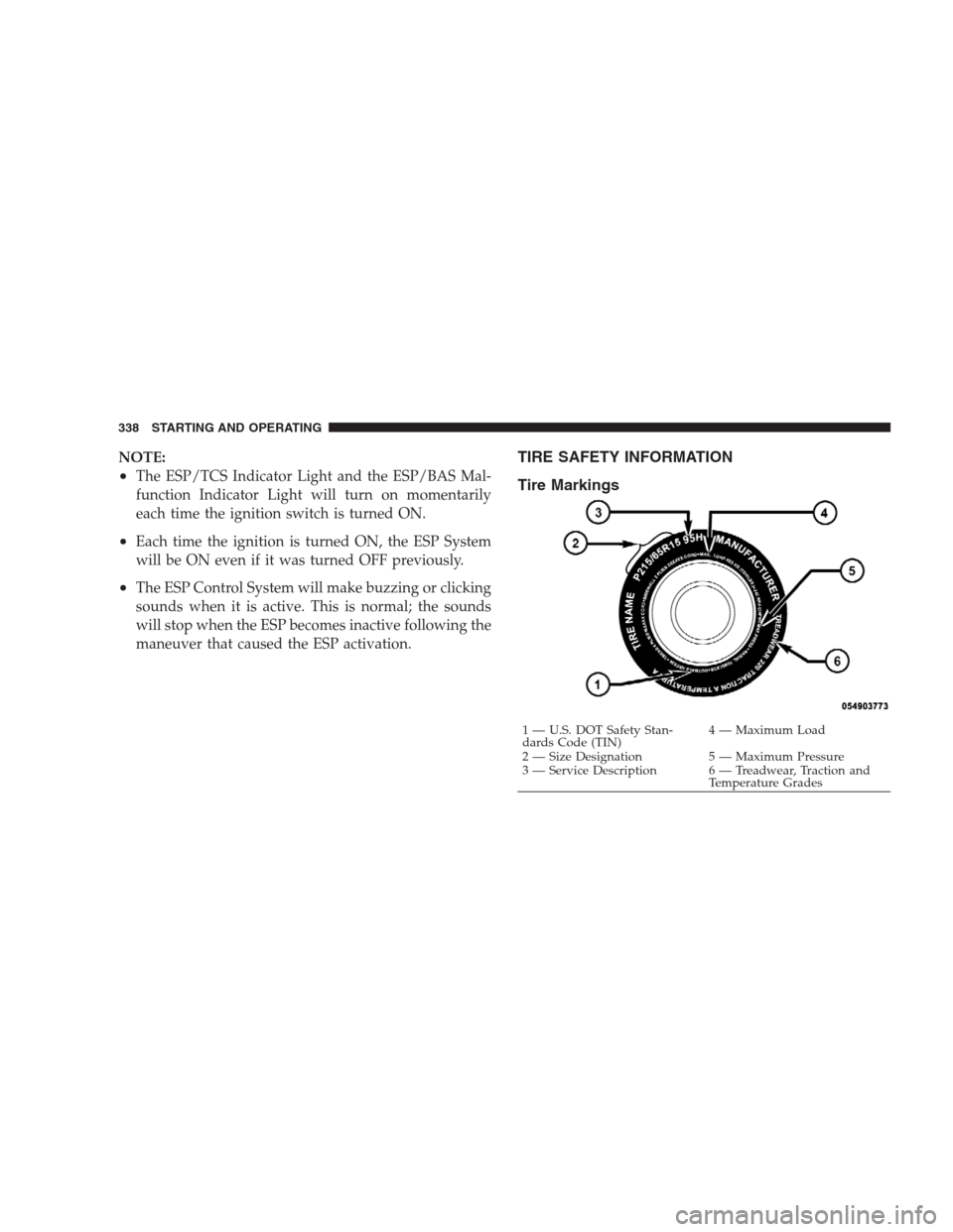
TIRE SAFETY INFORMATION
Tire Markings
1 — U.S. DOT Safety Stan-
dards Code (TIN)4 — Maximum Load
2 — Size Designation 5 — Maximum Pressure
3 — Service Description 6 — Treadwear, Traction and
Temperature Grades 338 STARTING AND OPERATING
Page 353 of 493
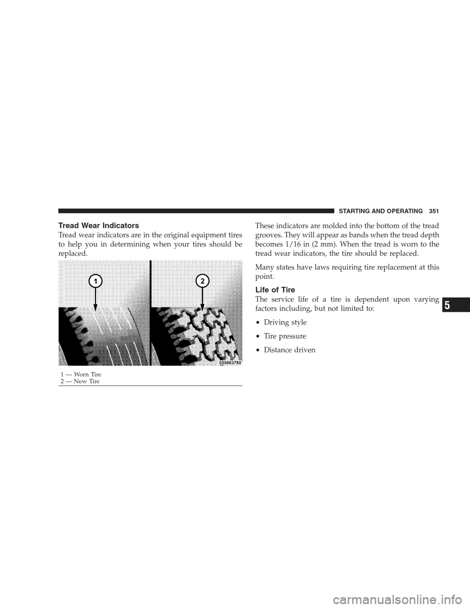
Tread Wear Indicators
Tread wear indicators are in the original equipment tires
to help you in determining when your tires should be
replaced.These indicators are molded into the bottom of the tread
grooves. They will appear as bands when the tread depth
becomes 1/16 in (2 mm). When the tread is worn to the
tread wear indicators, the tire should be replaced.
Many states have laws requiring tire replacement at this
point.
Life of Tire
The service life of a tire is dependent upon varying
factors including, but not limited to:
•Driving style
•Tire pressure
•Distance driven
1—WornTire
2—NewTireSTARTING AND OPERATING 351
5
Page 354 of 493
WARNING!
Tires and the spare tire should be replaced after six
years, regardless of the remaining tread. Failure to
follow this warning can result in sudden tire failure.
You could lose control and have an accident resulting
in serious injury or death.
Keep dismounted tires in a cool, dry place with as little
exposure to light as possible. Protect tires from contact
with oil, grease, and gasoline.
Replacement Tires
The tires on your new vehicle provide a balance of many
characteristics. They should be inspected regularly for
wear and correct cold tire inflation pressure. The manu-
facturer strongly recommends that you use tires equiva-
lent to the originals in size, quality and performance
when replacement is needed. (Refer to the paragraph on
“Tread Wear Indicators”). Refer to the “Tire and Loading
Information” placard for the size designation of your tire.
The service description and load identification will be
found on the original equipment tire. Failure to use
equivalent replacement tires may adversely affect the
safety, handling, and ride of your vehicle. We recommend
that you contact your original equipment or an autho-
rized tire dealer with any questions you may have on tire
specifications or capability.
352 STARTING AND OPERATING