battery CHRYSLER 300 SRT 2014 2.G User Guide
[x] Cancel search | Manufacturer: CHRYSLER, Model Year: 2014, Model line: 300 SRT, Model: CHRYSLER 300 SRT 2014 2.GPages: 132, PDF Size: 4.64 MB
Page 3 of 132
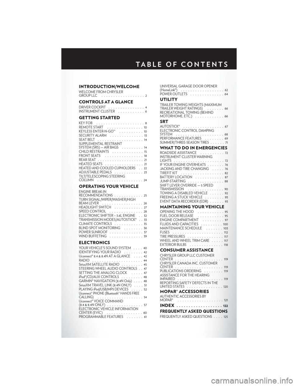
INTRODUCTION/WELCOME
WELCOME FROM CHRYSLER
GROUPLLC ..................2
CONTROLS AT A GLANCE
DRIVER COCKPIT...............4
INSTRUMENT CLUSTER ...........6
GETTING STARTED
KEYFOB ....................8
REMOTE START...............10
KEYLESS ENTER-N-GO™ ..........10
SECURITY ALARM ..............13
SEATBELT ...................14
SUPPLEMENTAL RESTRAINT
SYSTEM (SRS) — AIR BAGS .........14
CHILD RESTRAINTS .............15
FRONTSEATS ................18
REAR SEAT ...................21
HEATEDSEATS ................21
HEATED AND COOLED CUPHOLDERS..22
ADJUSTABLE PEDALS ............23
TILT/TELESCOPING STEERING
COLUMN ...................24
OPERATING YOUR VEHICLE
ENGINE BREAK-IN
RECOMMENDATIONS ............25
TURN SIGNAL/WIPER/WASHER/HIGH
BEAM LEVER . ................26
HEADLIGHT SWITCH ............27
SPEED CONTROL ..............28
ELECTRONIC SHIFTER – 3.6L ENGINE . . 32
TRANSMISSION MODES/AUTOSTICK® . . 33
CLIMATE CONTROLS ............35
BLIND SPOT MONITORING ........36
POWER SUNROOF ..............37
WIND BUFFETING ..............39
ELECTRONICS
YOUR VEHICLE'S SOUND SYSTEM ....40
IDENTIFYING YOUR RADIO ........42
Uconnect® 8.4 & 8.4N AT A GLANCE ....42
RADIO .....................44
SiriusXM SATELLITE RADIO .........45
STEERING WHEEL AUDIO CONTROLS . . 47
SETTING THE ANALOG CLOCK .....47
iPod®/CD/AUX CONTROLS .........48
GARMIN® NAVIGATION (8.4N Only) ....48
SiriusXM TRAVEL LINK (8.4N ONLY) . . . . 51
PLAYING iPod/USB/MP3 DEVICES .....52
Uconnect® PHONE (Bluetooth® HANDS FREE
CALLING)...................54
Uconnect® VOICE COMMAND
(8.4&8.4NONLY) ...............57
ELECTRONIC VEHICLE INFORMATION
CENTER (EVIC) ...............60
PROGRAMMABLE FEATURES .......61UNIVERSAL GARAGE DOOR OPENER
(HomeLink®)
..................62
POWER OUTLETS ..............64
UTILITY
TRAILER TOWING WEIGHTS (MAXIMUM
TRAILER WEIGHT RATINGS) . ......66
RECREATIONAL TOWING (BEHIND
MOTORHOME, ETC.) . . ..........66
SRTAUTOSTICK® .................67
ELECTRONIC CONTROL DAMPING
SYSTEM....................68
PERFORMANCE FEATURES ........69
SUMMER/THREE-SEASON TIRES ......71
WHAT TO DO IN EMERGENCIESROADSIDE ASSISTANCE..........72
INSTRUMENT CLUSTER WARNING
LIGHTS .....................72
IF YOUR ENGINE OVERHEATS .......76
JACKING AND TIRE CHANGING .....76
TIREFIT KIT ..................82
BATTERY LOCATION ............87
JUMP-STARTING ...............88
SHIFT LEVER OVERRIDE — 5 SPEED
TRANSMISSION ...............90
TOWING A DISABLED VEHICLE . . ....92
FREEING A STUCK VEHICLE ........93
EVENT DATA RECORDER (EDR) . . . . . . 93
MAINTAINING YOUR VEHICLEOPENING THE HOOD . . . ........95
FUEL DOOR RELEASE ...........95
ENGINE COMPARTMENT .........97
FLUIDSANDCAPACITIES .........100
MAINTENANCE SCHEDULE . . . . . . . 103
FUSES .....................112
TIRE PRESSURES ...............117
WHEEL AND WHEEL TRIM CARE . . . . . 117
EXTERIOR BULBS ..............118
CONSUMER ASSISTANCE
CHRYSLER GROUP LLC CUSTOMER
CENTER....................119
CHRYSLER CANADA INC. CUSTOMER
CENTER ....................119
PUBLICATIONS ORDERING ........119
ASSISTANCE FOR THE HEARING
IMPAIRED ...................119
REPORTING SAFETY DEFECTS IN THE
UNITEDSTATES ...............120
MOPAR® ACCESSORIESAUTHENTIC ACCESSORIES BY
MOPAR® ...................121
INDEX................... 122
FREQUENTLY ASKED QUESTIONS
FREQUENTLY ASKED QUESTIONS . . . . 125
TABLE OF CONTENTS
Page 11 of 132

Emergency Key
• Should the battery in the vehicle or the Key Fob transmitter go dead, there is an emergencykey located in the Key Fob. To remove the emergency key, slide the button at the back of the
Key Fob sideways with your thumb and then pull the key out with your other hand.
• The emergency key is also for locking the glove compartment.
WARNING!
• Never use the PARK position as a substitute for the parking brake. Always apply the parking brake fully when parked to guard against vehicle movement and possible injury or
damage.
• When leaving the vehicle, always remove the Key Fob from the ignition and lock your
vehicle.
• Never leave children alone in a vehicle, or with access to an unlocked vehicle. Allowing
children to be in a vehicle unattended is dangerous for a number of reasons. A child or
others could be seriously or fatally injured. Children should be warned not to touch the
parking brake, brake pedal or the shift lever.
• Do not leave the Key Fob in or near the vehicle, or in a location accessible to children, and
do not leave the ignition of a vehicle equipped with Keyless Enter-N-Go™ in the ACC or
ON/RUN mode. A child could operate power windows, other controls, or move the
vehicle.
Emergency Key
GETTING STARTED
9
Page 14 of 132

To Enter The Trunk:
• With a valid Keyless Enter-N-Go™ Key Foblocated outside the vehicle and within 3 ft
(1.0 m) of the deck lid, press the button on
the located on the center of the light bar
which is located on the deck lid above the
license plate.
NOTE:
Refer to your Owner's Manual on the DVD for
further information.
Engine Starting/Stopping
Starting
• With a valid Keyless Enter-N-Go™ Key Fob inside the vehicle.
• Shift the transmission to PARK or NEUTRAL.
• While pressing the brake pedal, press the ENGINE START/STOP button once. If the engine fails to start, the starter will disengage automatically after 10 seconds.
• To stop the cranking of the engine prior to the engine starting, press the button again.
NOTE:
In case the ignition switch does not change with
the push of a button, the RKE transmitter (Key
Fob) may have a low or dead battery. In this
situation a back up method can be used to
operate the ignition switch. Put the nose side of
the Key Fob (side opposite of the Emergency
Key) against the ENGINE START/STOP but-
ton and push to operate the ignition switch.
Stopping
1. Bring the vehicle to a complete stop.
2. Shift the transmission to PARK (P).
3. Press the ENGINE START/STOP button once. The ignition switch will return to the OFF position.
NOTE:
If the transmission is not in PARK and the vehicle is in motion, the ENGINE START/STOP
button must be held for two seconds with the vehicle speed above 5 mph (8 km/h) before
the engine will shut off.
GETTING STARTED
12
Page 55 of 132
• The functions of the portable device are controlled using the device buttons. The volume maybe controlled using the radio or portable device.
• To route the audio cable out of the center console, use the access cut out in the front of the console.
2. USB Port
• Connect your iPod® or compatible device using a USB cable into the USB Port. USB Memory sticks with audio files can also be used. Then, audio from the device can be played on the
vehicles sound system while providing metadata (artist, track title, album, etc.) information on
the radio display.
• When connected, the iPod®/compatible USB device can be controlled using the radio or Steering Wheel Audio Controls to play, skip to the next or previous track, browse, and list the
contents.
• The iPod® battery charges when plugged into the USB port (if supported by the specific device).
• To route the USB/iPod® cable out of the center console, use the access cut out in the front of the console.
NOTE:
When connecting your iPod® device for the first time, the system may take several minutes to
read your music, depending on the number of files. For example, the system will take approxi-
mately five minutes for every 1000 songs loaded on the device. Also during the reading process,
the Shuffle and Browse functions will be disabled. This process is needed to ensure the full use of
your iPod® features and only happens the first time it is connected. After the first time, the
reading process of your iPod® will take considerably less time unless changes are made or new
songs are added to the playlist.
• The USB port supports certain Mini, Classic, Nano, Touch, and iPhone® devices. The USB port also supports playing music from compatible external USB Mass Storage Class memory
devices. Some iPod® software versions may not fully support the USB port features. Please visit
Apple’s website for iPod® software updates.
3. SD Card
• Play songs stored on an SD card inserted into the SD card slot.
• Song playback can be controlled using the radio or Steering Wheel Audio Controls to play, skip to the next or previous track, browse, and list the contents.
4. Bluetooth® Streaming Audio
• If equipped with Uconnect® Voice Command, your Bluetooth-equipped iPod® devices, cell phones or other media players, may also be able to stream music to your vehicle's sound
system. Your connected device must be Bluetooth-compatible, and paired with your
Uconnect® system (see Uconnect® Phone for pairing instructions). You can access the music
from your connected Bluetooth® device by touching the Source soft-key while in Player mode.
ELECTRONICS
53
Page 64 of 132
UNIVERSAL GARAGE DOOR OPENER
(HomeLink®)
• HomeLink® replaces up to three hand-held transmitters that operate devices such as garagedoor openers, motorized gates, lighting or home security systems. The HomeLink® unit is
powered by your vehicles 12 Volt battery.
• The HomeLink® buttons that are located in the overhead console or sunvisor designate the three different HomeLink® channels.
• The HomeLink® indicator is located above the center button.
Before You Begin Programming
HomeLink®
• Ensure that your vehicle is parked outside of the garage before you begin programming.
• For efficient programming and accurate transmission of the radio-frequency signal,
it is recommended that a new battery be
placed in the hand-held transmitter of the
device that is being programmed to the
HomeLink® system.
• Erase all channels before you begin pro- gramming. To erase the channels, place the
ignition switch into the ON/RUN position,
then press and hold the two outside
HomeLink® buttons (I and III) for up to 20 seconds or until the red indicator flashes.
NOTE:
Erasing all channels should only be performed when programming HomeLink® for the first time.
Do not erase channels when programming additional buttons.
• If you have any problems, or require assistance, please call toll-free 1-800-355-3515 or, on the Internet at www.HomeLink.com for information or assistance.
Programming A Rolling Code
NOTE:
For programming Garage Door Openers that were manufactured after 1995. These Garage
Door Openers can be identified by the “LEARN” or “TRAIN” button located where the hanging
antenna is attached to the Garage Door Opener. It is NOT the button that is normally used to
open and close the door. The name and color of the button may vary by manufacturer.
1. Place the ignition switch into the ON/RUN position.
2. Place the hand-held transmitter 1 to 3 in (3 to 8 cm) away from the HomeLink® button you wish
to program while keeping the HomeLink® indicator light in view.
3. Simultaneously press and hold both the HomeLink® button you want to program and the hand-held transmitter button.
ELECTRONICS
62
Page 66 of 132

Using HomeLink®
• To operate, press and release the programmed HomeLink® button. Activation will now occurfor the programmed device (e.g., garage door opener, gate operator, security system, entry
door lock, home/office lighting, etc.,). The hand-held transmitter of the device may also be
used at any time.
WARNING!
•Your motorized door or gate will open and close while you are programming the universal
transceiver. Do not program the transceiver if people or pets are in the path of the door or gate.
• Do not run your vehicle in a closed garage or confined area while programming the
transceiver. Exhaust gas from your vehicle contains Carbon Monoxide (CO) which is
odorless and colorless. Carbon Monoxide is poisonous when inhaled and can cause you
and others to be severely injured or killed.
POWER OUTLETS
• There are three 12 Volt electrical outlets onthis vehicle.
• The front 12 Volt power outlet has power available only when the ignition is placed in
the ACC or RUN position.
• The center console outlet is powered di- rectly from the battery (power available at all
times). Items plugged into this outlet may
discharge the battery and/or prevent the
engine from starting.
• There is also a 12 Volt power outlet located on the back of the center console for rear passengers. This power outlet has power available
only when the ignition is placed in the ACC or RUN position.
NOTE:
• Do not exceed the maximum power of 160 Watts (13 Amps) at 12 Volts. If the 160 Watt (13 Amp) power rating is exceeded, the fuse protecting the system will need to be replaced.
ELECTRONICS
64
Page 72 of 132
1/8 Mile, 1/4 Mile
• When selected, this screen displays the time it takes the vehicle to travel 1/8 mile (1/4 mile)within 30 seconds and the vehicle's speed when it reaches 1/8 mile (1/4 mile).
Instantaneous G-Force
• When selected, this screen displays the current G-Force (lateral and longitudinal) along witha friction circle that displays the directions of the forces.
Peak G-Force
• When selected, this screen displays all four G-Force values (two lateral and two longitudinal).
Uconnect® SRT Performance Features
• To access the SRT Performance Features, touch the “More” soft-key then touch the “SRT”soft-key. Press the UP or DOWN soft-key to cycle through the features. Press the feature
soft-key to select that feature.
• The Performance Page include the following:
• Timers • 1/8 Mile
• Engine Values • 1/4 Mile
• Digital Gauge Displays • Instantaneous G-Force
• 0-60 mph (0-100 km/h) • Peak G-Force
• Braking Distance • Digital Speedometer
Timers
0-60 mph (0-100 km/h), 1/8 Mile, 1/4 Mile
• When selected, this screen displays the time it takes for the vehicle to go from 0 to 60 mph (0 to 100 km/h), 1/8 mile or 1/4 mile.
Braking Distance
• When selected, this screen displays the vehicle's braking distance and the speed at which thebrake pedal was depressed.
G-Force
• When selected, this screen displays all four G-Force values (two lateral and two longitudinal)as well as steering angle.
Gauges 1
• Oil Temperature
• Oil Pressure
• Battery Voltage
SRT
70
Page 73 of 132
Gauges 2
• Coolant Temperature
• Oil Temperature
• Transmission Temperature
• Intake Air Temperature
• Oil Pressure
• Battery Voltage
Engine
• When selected, this screen displays miles per hour (mph), horsepower (hp), torque (ft/lb), oilpressure (psi) and gear selector values.
Handling
•When selected, this screen displays peak g-force, instantaneous g-force, steering and yaw angles.
Options
• When selected, this screen allows you to choose a standard or custom display for your SRThome page.
WARNING!
Measurement of vehicle statistics with the Performance Features is intended for off-highway
or off-road use only and should not be done on any public roadways. It is recommended
that these features be used in a controlled environment and within the limits of the law. The
capabilities of the vehicle as measured by the performance pages must never be exploited in
a reckless or dangerous manner, which can jeopardize the user’s safety or the safety of others.
Only a safe, attentive, and skillful driver can prevent accidents.
SUMMER/THREE-SEASON TIRES
• This vehicle may be equipped with wheels and tires to enhance traction in both wet and dryconditions.
• Summer tires are not intended to be driven in snow or on ice.
• Summer tires have significantly reduced grip in temperatures below 50°F (10°C)
• Use summer tires only in sets of four.
NOTE:
Summer tires will not contain the all season designation or mountain/snowflake symbol on the
sidewall of the tire.
WARNING!
Do not use summer tires in snow/ice conditions. You could lose control, resulting in severe injury or
death. Driving too fast for conditions also creates the possibility of loss of vehicle control.
SRT
71
Page 89 of 132

WARNING!
• Do not attempt to seal a tire on the side of the vehicle closest to traffic. Pull far enough offthe road to avoid the danger of being hit when using the TIREFIT kit.
• Do not use TIREFIT or drive the vehicle under the following circumstances:
• If the puncture in the tire tread is approximately 1/4 in. (6 mm) or larger.
• If the tire has any sidewall damage.
• If the tire has any damage from driving with extremely low tire pressure.
• If the tire has any damage from driving on a flat tire.
• If the wheel has any damage.
• If you are unsure of the condition of the tire or the wheel.
• Keep TIREFIT away from open flames or heat source.
• A loose TIREFIT kit thrown forward in a collision or hard stop could endanger the
occupants of the vehicle. Always stow the TIREFIT kit in the place provided. Failure to
follow these warnings can result in injuries that are serious or fatal to you, your passengers,
and others around you.
• Take care not to allow the contents of TIREFIT to come in contact with hair, eyes, or
clothing. TIREFIT is harmful if inhaled, swallowed, or absorbed through the skin. It causes
skin, eye, and respiratory irritation. Flush immediately with plenty of water if there is any
contact with eyes or skin. Change clothing as soon as possible, if there is any contact with
clothing.
• TIREFIT Sealant solution contains latex. In case of an allergic reaction or rash, consult a
physician immediately. Keep TIREFIT out of reach of children. If swallowed, rinse mouth
immediately with plenty of water and drink plenty of water. Do not induce vomiting!
Consult a physician immediately.
• TIREFIT is not a permanent flat tire repair. Have the tire inspected and repaired or
replaced after using TIREFIT. Do not exceed 55 mph (88 km/h) until the tire is repaired or
replaced. Failure to follow this warning can result in injuries that are serious or fatal to you,
your passengers, and others around you.
BATTERY LOCATION
• The battery is stored under an access cover in the trunk. Remote battery posts are located onthe right side of the engine compartment for jump-starting.
WHAT TO DO IN EMERGENCIES
87
Page 90 of 132

JUMP-STARTING
• If your vehicle has a discharged battery itcan be jump-started using a set of jumper
cables and a battery in another vehicle or by
using a portable battery booster pack.
• Jump-starting can be dangerous if done im- properly so please follow the procedures in
this section carefully.
NOTE:
When using a portable battery booster pack
follow the manufacturer’s operating instruc-
tions and precautions.
Preparations For Jump-Start
• The battery is stored under an access cover in the trunk. Remote battery posts are lo-
cated on the right side of the engine compartment for jump-starting.
NOTE:
The remote battery posts are viewed by standing on the right side of the vehicle looking over the
fender.
• Set the parking brake, shift the automatic transmission into PARK and turn the ignition to OFF.
• Turn off the heater, radio, and all unnecessary electrical accessories.
• If using another vehicle to jump-start the battery, park the vehicle within the jumper cables reach, set the parking brake and make sure the ignition is OFF.
Jump-Starting Procedure
1. Connect the positive (+)end of the jumper cable to the remote positive (+)post of the
discharged vehicle.
2. Connect the opposite end of the positive (+)jumper cable to the positive (+)post of the
booster battery.
3. Connect the negative end (-)of the jumper cable to the negative (-)post of the booster
battery.
4. Connect the opposite end of the negative (-)jumper cable to the remote negative (-)post of
the vehicle with the discharged battery.
5. Start the engine in the vehicle that has the booster battery, let the engine idle a few minutes, and then start the engine in the vehicle with the discharged battery.
Once the engine is started, remove the jumper cables in the reverse sequence:
1. Disconnect the negative (-)jumper cable from the remote negative (-)post of the vehicle with
the discharged battery.
WHAT TO DO IN EMERGENCIES
88