wheel CHRYSLER CARAVAN 2002 Service Manual
[x] Cancel search | Manufacturer: CHRYSLER, Model Year: 2002, Model line: CARAVAN, Model: CHRYSLER CARAVAN 2002Pages: 2399, PDF Size: 57.96 MB
Page 225 of 2399
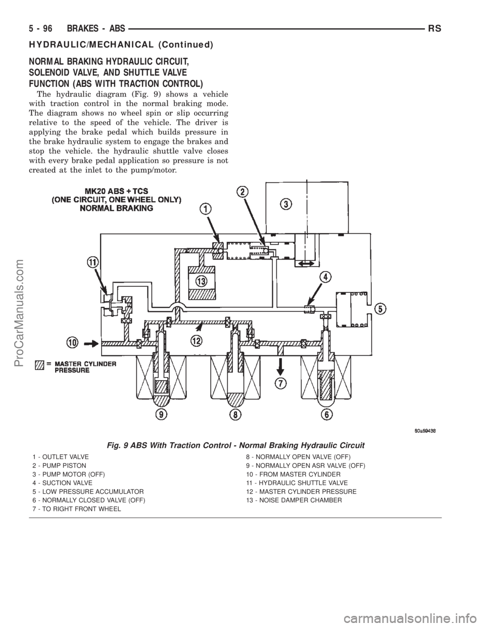
NORMAL BRAKING HYDRAULIC CIRCUIT,
SOLENOID VALVE, AND SHUTTLE VALVE
FUNCTION (ABS WITH TRACTION CONTROL)
The hydraulic diagram (Fig. 9) shows a vehicle
with traction control in the normal braking mode.
The diagram shows no wheel spin or slip occurring
relative to the speed of the vehicle. The driver is
applying the brake pedal which builds pressure in
the brake hydraulic system to engage the brakes and
stop the vehicle. the hydraulic shuttle valve closes
with every brake pedal application so pressure is not
created at the inlet to the pump/motor.
Fig. 9 ABS With Traction Control - Normal Braking Hydraulic Circuit
1 - OUTLET VALVE
2 - PUMP PISTON
3 - PUMP MOTOR (OFF)
4 - SUCTION VALVE
5 - LOW PRESSURE ACCUMULATOR
6 - NORMALLY CLOSED VALVE (OFF)
7 - TO RIGHT FRONT WHEEL8 - NORMALLY OPEN VALVE (OFF)
9 - NORMALLY OPEN ASR VALVE (OFF)
10 - FROM MASTER CYLINDER
11 - HYDRAULIC SHUTTLE VALVE
12 - MASTER CYLINDER PRESSURE
13 - NOISE DAMPER CHAMBER
5 - 96 BRAKES - ABSRS
HYDRAULIC/MECHANICAL (Continued)
ProCarManuals.com
Page 226 of 2399
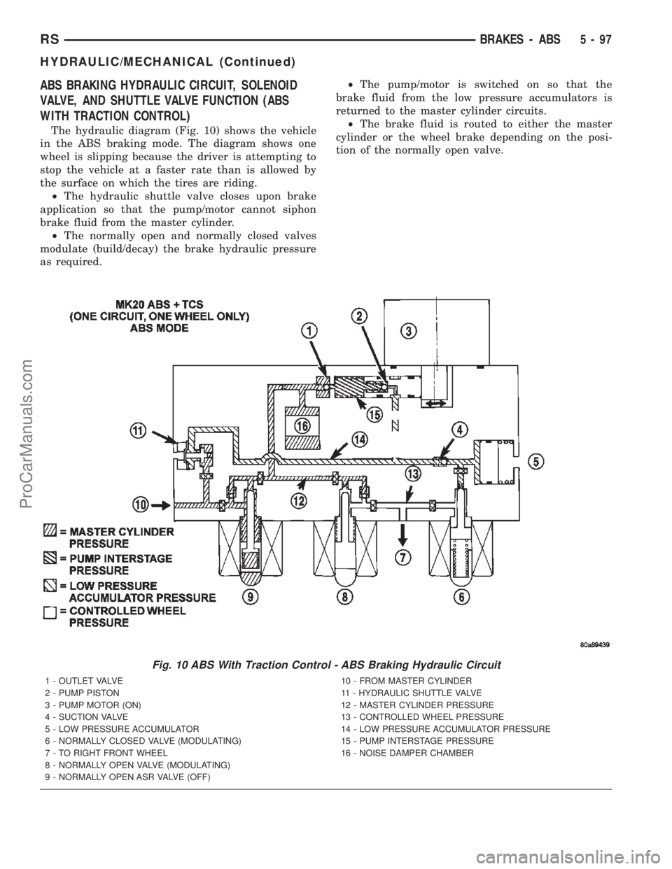
ABS BRAKING HYDRAULIC CIRCUIT, SOLENOID
VALVE, AND SHUTTLE VALVE FUNCTION (ABS
WITH TRACTION CONTROL)
The hydraulic diagram (Fig. 10) shows the vehicle
in the ABS braking mode. The diagram shows one
wheel is slipping because the driver is attempting to
stop the vehicle at a faster rate than is allowed by
the surface on which the tires are riding.
²The hydraulic shuttle valve closes upon brake
application so that the pump/motor cannot siphon
brake fluid from the master cylinder.
²The normally open and normally closed valves
modulate (build/decay) the brake hydraulic pressure
as required.²The pump/motor is switched on so that the
brake fluid from the low pressure accumulators is
returned to the master cylinder circuits.
²The brake fluid is routed to either the master
cylinder or the wheel brake depending on the posi-
tion of the normally open valve.
Fig. 10 ABS With Traction Control - ABS Braking Hydraulic Circuit
1 - OUTLET VALVE
2 - PUMP PISTON
3 - PUMP MOTOR (ON)
4 - SUCTION VALVE
5 - LOW PRESSURE ACCUMULATOR
6 - NORMALLY CLOSED VALVE (MODULATING)
7 - TO RIGHT FRONT WHEEL
8 - NORMALLY OPEN VALVE (MODULATING)
9 - NORMALLY OPEN ASR VALVE (OFF)10 - FROM MASTER CYLINDER
11 - HYDRAULIC SHUTTLE VALVE
12 - MASTER CYLINDER PRESSURE
13 - CONTROLLED WHEEL PRESSURE
14 - LOW PRESSURE ACCUMULATOR PRESSURE
15 - PUMP INTERSTAGE PRESSURE
16 - NOISE DAMPER CHAMBER
RSBRAKES - ABS5-97
HYDRAULIC/MECHANICAL (Continued)
ProCarManuals.com
Page 227 of 2399
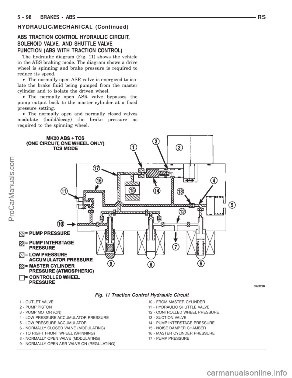
ABS TRACTION CONTROL HYDRAULIC CIRCUIT,
SOLENOID VALVE, AND SHUTTLE VALVE
FUNCTION (ABS WITH TRACTION CONTROL)
The hydraulic diagram (Fig. 11) shows the vehicle
in the ABS braking mode. The diagram shows a drive
wheel is spinning and brake pressure is required to
reduce its speed.
²The normally open ASR valve is energized to iso-
late the brake fluid being pumped from the master
cylinder and to isolate the driven wheel.
²The normally open ASR valve bypasses the
pump output back to the master cylinder at a fixed
pressure setting.
²The normally open and normally closed valves
modulate (build/decay) the brake pressure as
required to the spinning wheel.
Fig. 11 Traction Control Hydraulic Circuit
1 - OUTLET VALVE
2 - PUMP PISTON
3 - PUMP MOTOR (ON)
4 - LOW PRESSURE ACCUMULATOR PRESSURE
5 - LOW PRESSURE ACCUMULATOR
6 - NORMALLY CLOSED VALVE (MODULATING)
7 - TO RIGHT FRONT WHEEL (SPINNING)
8 - NORMALLY OPEN VALVE (MODULATING)
9 - NORMALLY OPEN ASR VALVE ON (REGULATING)10 - FROM MASTER CYLINDER
11 - HYDRAULIC SHUTTLE VALVE
12 - CONTROLLED WHEEL PRESSURE
13 - SUCTION VALVE
14 - PUMP INTERSTAGE PRESSURE
15 - NOISE DAMPER CHAMBER
16 - MASTER CYLINDER PRESSURE
17 - PUMP PRESSURE
5 - 98 BRAKES - ABSRS
HYDRAULIC/MECHANICAL (Continued)
ProCarManuals.com
Page 228 of 2399
HCU (HYDRAULIC CONTROL
UNIT)
DESCRIPTION
The hydraulic control unit (HCU) is mounted to
the CAB as part of the ICU (Fig. 22). The HCU con-
trols the flow of brake fluid to the brakes using a
series of valves and accumulators. A pump/motor is
mounted on the HCU to supply build pressure to the
brakes during an ABS stop.
The HCU on a vehicle equipped with ABS and
traction control has a valve block housing that is
approximately 1 inch longer on the low pressure fluid
accumulators side than a HCU on a vehicle that is
equipped with only ABS.
For more information, (Refer to 5 - BRAKES/HY-
DRAULIC/MECHANICAL/ICU (INTEGRATED CON-
TROL UNIT) - DESCRIPTION)
OPERATION
For information on the operation of the HCU as a
whole, refer to Hydraulic Circuits And Valve Opera-
tion which can be found elsewhere in this section.
For information on the operation of the components
within the HCU, refer to the following three topics.
VALVES AND SOLENOIDS
The valve block contains four inlet valves and four
outlet valves. The inlet valves are spring-loaded in
the open position and the outlet valves are spring-
loaded in the closed position during normal braking.
The fluid is allowed to flow from the master cylinder
to the wheel brakes.
During an ABS stop, these valves cycle to maintain
the proper slip ratio for each wheel. The inlet valve
closes preventing further pressure increase and the
outlet valve opens to provide a path from the wheel
brake to the HCU accumulators and pump/motor.
This releases (decays) pressure from the wheel brake,
thus releasing the wheel from excessive slippage.
Once the wheel is no longer slipping, the outlet valve
is closed and the inlet valve is opened to reapply
(build) pressure.
On vehicles with traction control, there is an extra
set of valves and solenoids. The ASR valves, mounted
in the HCU valve block, are normally in the open
position and close only when the traction control is
applied.
These isolator valves are used to isolate the rear
(non-driving) wheels of the vehicle from the hydraulicpressure that the HCU pump/motor is sending to the
front (driving) wheels when traction control is being
applied. The rear brakes need to be isolated from the
master cylinder when traction control is being
applied so the rear wheels do not drag. For more
information, refer to Traction Control System in this
section.
BRAKE FLUID ACCUMULATORS
There are two fluid accumulators in the HCU±one
for the primary hydraulic circuit and one for the sec-
ondary hydraulic circuit. Each hydraulic circuit uses
a 5 cc accumulator.
The fluid accumulators temporarily store brake
fluid that is removed from the wheel brakes during
an ABS cycle. This stored fluid is used by the pump/
motor to provide build pressure for the brake hydrau-
lic system. When the antilock stop is complete, the
accumulators are drained by the pump/motor.
On ABS-only vehicles, there is a mini-accumulator
on the secondary hydraulic circuit that protects the
master cylinder seals during an ABS stop, and there
is a noise dampening chamber on the primary circuit.
On ABS with traction control vehicles, there are
two noise dampening chambers in the HCU.
PUMP/MOTOR
There are two pump assemblies in the HCUÐone
for the primary hydraulic circuit and one for the sec-
ondary hydraulic circuit. Both pumps are driven by a
common electric motor. This DC-type motor is inte-
gral to the HCU and is controlled by the CAB.
The pump/motor provides the extra amount of
brake fluid needed during antilock braking. Brake
fluid is released to the accumulators when the outlet
valve is opened during an antilock stop. The pump
mechanism consists of two opposing pistons operated
by an eccentric camshaft. In operation, one piston
draws fluid from the accumulators, and the opposing
piston pumps fluid to the master cylinder circuits.
When the antilock stop is complete, the pump/motor
drains the accumulators.
The CAB may turn on the pump/motor when an
antilock stop is detected. The pump/motor continues
to run during the antilock stop and is turned off after
the stop is complete. Under some conditions, the
pump/motor runs to drain the accumulators during
the next drive-off.
The pump/motor is not a serviceable item; if it
requires replacement, the HCU must be replaced.
RSBRAKES - ABS5-99
ProCarManuals.com
Page 230 of 2399
(7) Using a brake pedal depressor, move and lock
the brake pedal to a position past the first inch of
pedal travel.This will prevent brake fluid from
draining out of the master cylinder once the
brake tubes are removed from the HCU.
CAUTION: Do not apply a 12±volt power source to
any terminals of the 24-way CAB connector when
disconnected.
(8) Disconnect the wiring harness connector from
the speed control servo.
(9) Remove the speed control servo mounting nuts
and move the servo out of the way.
(10) Disconnect the 24±way connector from the
CAB. To disconnect the 24±way connector, grasp the
lock on the 24±way connector and pull it as far up as
possible. This will unlock the 24±way connector from
the socket on the CAB.
CAUTION: Before removing the brake tubes from
the HCU, the HCU must be thoroughly cleaned. This
must be done to prevent dirt particles from falling
into the ports of HCU or entering the brake tubes.
(11) Thoroughly clean all surfaces of the ICU and
brake tube nuts. Use only a solvent such as Mopart
Brake Parts Cleaner or equivalent to clean the ICU.
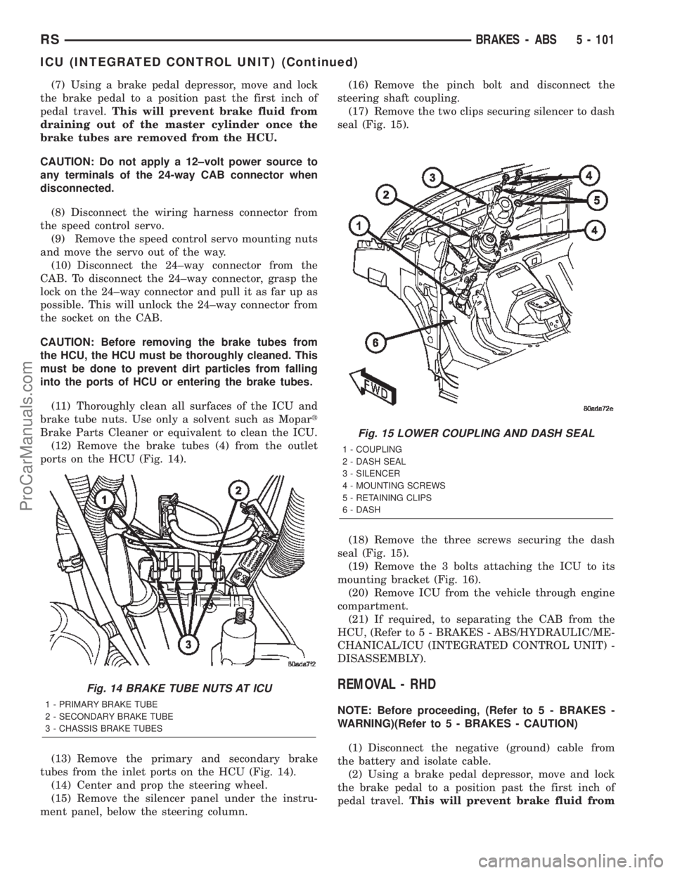
(12) Remove the brake tubes (4) from the outlet
ports on the HCU (Fig. 14).
(13) Remove the primary and secondary brake
tubes from the inlet ports on the HCU (Fig. 14).
(14) Center and prop the steering wheel.
(15) Remove the silencer panel under the instru-
ment panel, below the steering column.(16) Remove the pinch bolt and disconnect the
steering shaft coupling.
(17) Remove the two clips securing silencer to dash
seal (Fig. 15).
(18) Remove the three screws securing the dash
seal (Fig. 15).
(19) Remove the 3 bolts attaching the ICU to its
mounting bracket (Fig. 16).
(20) Remove ICU from the vehicle through engine
compartment.
(21) If required, to separating the CAB from the
HCU, (Refer to 5 - BRAKES - ABS/HYDRAULIC/ME-
CHANICAL/ICU (INTEGRATED CONTROL UNIT) -
DISASSEMBLY).
REMOVAL - RHD
NOTE: Before proceeding, (Refer to 5 - BRAKES -
WARNING)(Refer to 5 - BRAKES - CAUTION)
(1) Disconnect the negative (ground) cable from
the battery and isolate cable.
(2) Using a brake pedal depressor, move and lock
the brake pedal to a position past the first inch of
pedal travel.This will prevent brake fluid from
Fig. 14 BRAKE TUBE NUTS AT ICU
1 - PRIMARY BRAKE TUBE
2 - SECONDARY BRAKE TUBE
3 - CHASSIS BRAKE TUBES
Fig. 15 LOWER COUPLING AND DASH SEAL
1 - COUPLING
2 - DASH SEAL
3 - SILENCER
4 - MOUNTING SCREWS
5 - RETAINING CLIPS
6 - DASH
RSBRAKES - ABS5 - 101
ICU (INTEGRATED CONTROL UNIT) (Continued)
ProCarManuals.com
Page 232 of 2399
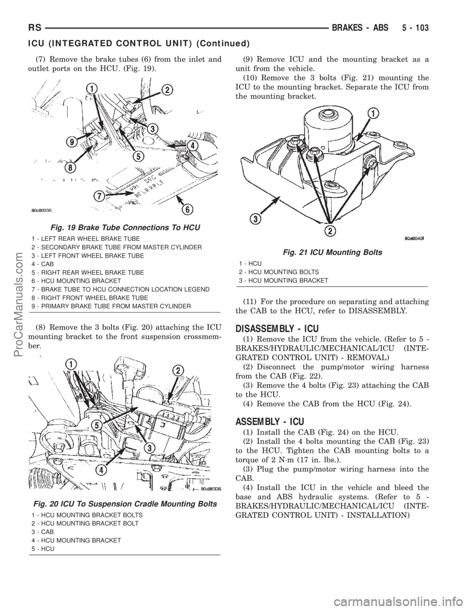
(7) Remove the brake tubes (6) from the inlet and
outlet ports on the HCU. (Fig. 19).
(8) Remove the 3 bolts (Fig. 20) attaching the ICU
mounting bracket to the front suspension crossmem-
ber.(9) Remove ICU and the mounting bracket as a
unit from the vehicle.
(10) Remove the 3 bolts (Fig. 21) mounting the
ICU to the mounting bracket. Separate the ICU from
the mounting bracket.
(11) For the procedure on separating and attaching
the CAB to the HCU, refer to DISASSEMBLY.
DISASSEMBLY - ICU
(1) Remove the ICU from the vehicle. (Refer to 5 -
BRAKES/HYDRAULIC/MECHANICAL/ICU (INTE-
GRATED CONTROL UNIT) - REMOVAL)
(2) Disconnect the pump/motor wiring harness
from the CAB (Fig. 22).
(3) Remove the 4 bolts (Fig. 23) attaching the CAB
to the HCU.
(4) Remove the CAB from the HCU (Fig. 24).
ASSEMBLY - ICU
(1) Install the CAB (Fig. 24) on the HCU.
(2) Install the 4 bolts mounting the CAB (Fig. 23)
to the HCU. Tighten the CAB mounting bolts to a
torque of 2 N´m (17 in. lbs.).
(3) Plug the pump/motor wiring harness into the
CAB.
(4) Install the ICU in the vehicle and bleed the
base and ABS hydraulic systems. (Refer to 5 -
BRAKES/HYDRAULIC/MECHANICAL/ICU (INTE-
GRATED CONTROL UNIT) - INSTALLATION)
Fig. 19 Brake Tube Connections To HCU
1 - LEFT REAR WHEEL BRAKE TUBE
2 - SECONDARY BRAKE TUBE FROM MASTER CYLINDER
3 - LEFT FRONT WHEEL BRAKE TUBE
4 - CAB
5 - RIGHT REAR WHEEL BRAKE TUBE
6 - HCU MOUNTING BRACKET
7 - BRAKE TUBE TO HCU CONNECTION LOCATION LEGEND
8 - RIGHT FRONT WHEEL BRAKE TUBE
9 - PRIMARY BRAKE TUBE FROM MASTER CYLINDER
Fig. 20 ICU To Suspension Cradle Mounting Bolts
1 - HCU MOUNTING BRACKET BOLTS
2 - HCU MOUNTING BRACKET BOLT
3 - CAB
4 - HCU MOUNTING BRACKET
5 - HCU
Fig. 21 ICU Mounting Bolts
1 - HCU
2 - HCU MOUNTING BOLTS
3 - HCU MOUNTING BRACKET
RSBRAKES - ABS5 - 103
ICU (INTEGRATED CONTROL UNIT) (Continued)
ProCarManuals.com
Page 233 of 2399
INSTALLATION
INSTALLATION - LHD
(1) Place the ICU in its bracket below the master
cylinder. Start the upper mounting bolt to hold it in
place.
(2) Inside the vehicle, install the remaining 2
mounting bolts attaching the ICU to the mounting
bracket (Fig. 16). Tighten all 3 mounting bolts to a
torque of 11 N´m (97 in. lbs.).
(3) Install the dash seal and three mounting
screws (Fig. 15).(4) Install the silencer on top of the dash seal (Fig.
15).
(5) Connect the steering shaft coupling and install
the pinch bolt (Fig. 15). Tighten the pinch bolt to 28
N´m (250 in. lbs.).
(6) Install the silencer panel below the steering
column under the instrument panel.
(7) Remove the steering wheel holder.
CAUTION: Because of the flexible section in the pri-
mary and secondary brake tubes, the brake tubes
must be held in proper orientation when tightened
and torqued. These tubes must not contact each
other or other vehicle components when installed.
Also, after the brake tubes are installed on the HCU,
ensure all spacer clips are reinstalled on the brake
tubes.
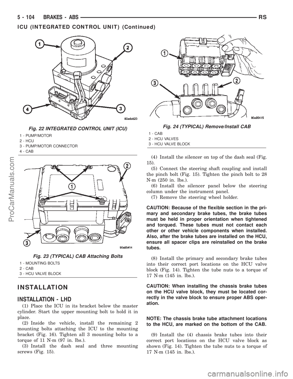
(8) Install the primary and secondary brake tubes
into their correct port locations on the HCU valve
block (Fig. 14). Tighten the tube nuts to a torque of
17 N´m (145 in. lbs.).
CAUTION: When installing the chassis brake tubes
on the HCU valve block, they must be located cor-
rectly in the valve block to ensure proper ABS oper-
ation.
NOTE: The chassis brake tube attachment locations
to the HCU, are marked on the bottom of the CAB.
(9) Install the (4) chassis brake tubes into their
correct port locations on the HCU valve block as
shown (Fig. 14). Tighten the tube nuts to a torque of
17 N´m (145 in. lbs.).
Fig. 22 INTEGRATED CONTROL UNIT (ICU)
1 - PUMP/MOTOR
2 - HCU
3 - PUMP/MOTOR CONNECTOR
4 - CAB
Fig. 23 (TYPICAL) CAB Attaching Bolts
1 - MOUNTING BOLTS
2 - CAB
3 - HCU VALVE BLOCK
Fig. 24 (TYPICAL) Remove/Install CAB
1 - CAB
2 - HCU VALVES
3 - HCU VALVE BLOCK
5 - 104 BRAKES - ABSRS
ICU (INTEGRATED CONTROL UNIT) (Continued)
ProCarManuals.com
Page 236 of 2399
CLUTCH
TABLE OF CONTENTS
page page
CLUTCH
DESCRIPTION..........................1
DIAGNOSIS AND TESTING
DIAGNOSIS AND TESTING - CLUTCH
SYSTEM.............................3
DIAGNOSIS AND TESTING - DRIVE PLATE
MISALIGNMENT.......................5
DIAGNOSIS AND TESTING - CLUTCH
COVER AND DISC RUNOUT..............6
DIAGNOSIS AND TESTING - CLUTCH
CHATTER COMPLAINTS.................6
SPECIAL TOOLS - T850 TRANSAXLE........6
CLUTCH RELEASE LEVER AND BEARING
REMOVAL.............................6
INSTALLATION..........................7
MASTER CYLINDER - RHD
REMOVAL.............................8INSTALLATION..........................8
MASTER CYLINDER - LHD
REMOVAL.............................9
INSTALLATION.........................10
MODULAR CLUTCH ASSY - 2.4L GAS
REMOVAL.............................11
INSTALLATION.........................11
SLAVE CYLINDER
REMOVAL.............................11
INSTALLATION.........................11
CLUTCH DISC AND PRESSURE PLATE - 2.5L
TD
REMOVAL.............................12
INSTALLATION.........................12
FLYWHEEL
REMOVAL.............................13
INSTALLATION.........................13
CLUTCH
DESCRIPTION
CLUTCH COMPONENTS
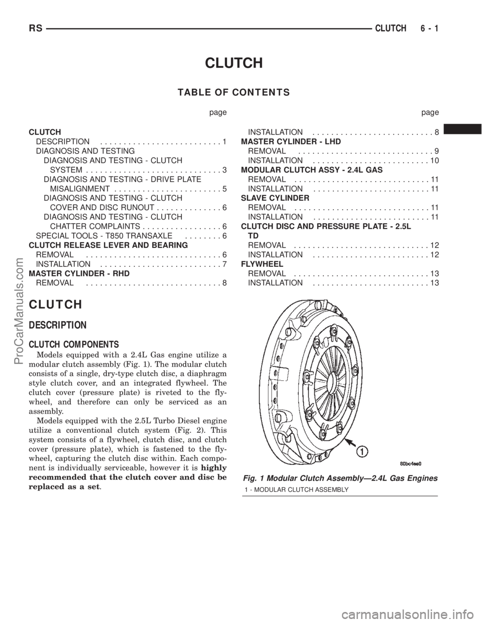
Models equipped with a 2.4L Gas engine utilize a
modular clutch assembly (Fig. 1). The modular clutch
consists of a single, dry-type clutch disc, a diaphragm
style clutch cover, and an integrated flywheel. The
clutch cover (pressure plate) is riveted to the fly-
wheel, and therefore can only be serviced as an
assembly.
Models equipped with the 2.5L Turbo Diesel engine
utilize a conventional clutch system (Fig. 2). This
system consists of a flywheel, clutch disc, and clutch
cover (pressure plate), which is fastened to the fly-
wheel, capturing the clutch disc within. Each compo-
nent is individually serviceable, however it ishighly
recommended that the clutch cover and disc be
replaced as a set.
Fig. 1 Modular Clutch AssemblyÐ2.4L Gas Engines
1 - MODULAR CLUTCH ASSEMBLY
RSCLUTCH6-1
ProCarManuals.com
Page 237 of 2399
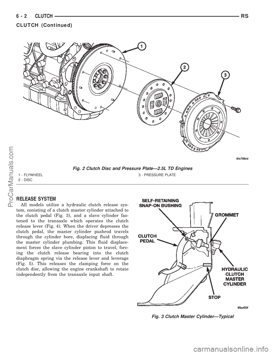
RELEASE SYSTEM
All models utilize a hydraulic clutch release sys-
tem, conisting of a clutch master cylinder attached to
the clutch pedal (Fig. 3), and a slave cylinder fas-
tened to the transaxle which operates the clutch
release lever (Fig. 4). When the driver depresses the
clutch pedal, the master cylinder pushrod travels
through the cylinder bore, displacing fluid through
the master cylinder plumbing. This fluid displace-
ment forces the slave cylinder piston to travel, forc-
ing the clutch release bearing into the clutch
diaphragm spring via the release lever and leverage
(Fig. 5). This releases the clamping force on the
clutch disc, allowing the engine crankshaft to rotate
independently from the transaxle input shaft.
Fig. 2 Clutch Disc and Pressure PlateÐ2.5L TD Engines
1 - FLYWHEEL
2 - DISC3 - PRESSURE PLATE
Fig. 3 Clutch Master CylinderÐTypical
6 - 2 CLUTCHRS
CLUTCH (Continued)
ProCarManuals.com
Page 240 of 2399
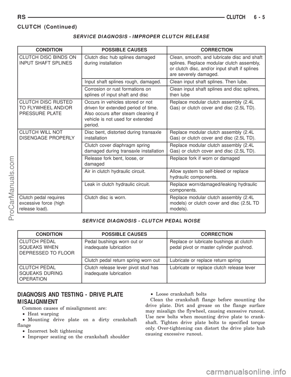
SERVICE DIAGNOSIS - IMPROPER CLUTCH RELEASE
CONDITION POSSIBLE CAUSES CORRECTION
CLUTCH DISC BINDS ON
INPUT SHAFT SPLINESClutch disc hub splines damaged
during installationClean, smooth, and lubricate disc and shaft
splines. Replace modular clutch assembly,
or clutch disc, and/or input shaft if splines
are severely damaged.
Input shaft splines rough, damaged. Clean input shaft splines. Then lube.
Corrosion or rust formations on
splines of input shaft and discClean input shaft splines and disc splines,
then lube
CLUTCH DISC RUSTED
TO FLYWHEEL AND/OR
PRESSURE PLATEOccurs in vehicles stored or not
driven for extended period of time.
Also occurs after steam cleaning if
vehicle is not used for extended
period.Replace modular clutch assembly (2.4L
Gas) or clutch cover and disc (2.5L TD).
CLUTCH WILL NOT
DISENGAGE PROPERLYDisc bent, distorted during transaxle
installationReplace modular clutch assembly (2.4L
Gas) or clutch cover and disc (2.5L TD).
Clutch cover diaphragm spring
damaged during transaxle installationReplace modular clutch assembly (2.4L
Gas) or clutch cover and disc (2.5L TD).
Release fork bent, loose, or
damagedReplace fork if worn or damaged
Air in clutch hydraulic circuit. Allow system to self-bleed or replace
hydraulic components.
Leak in clutch hydraulic circuit. Replace worn/damaged/leaking hydraulic
components.
Clutch pedal requires
excessive force (high
release load).Clutch disc is worn. Replace modular clutch assembly (2.4L
models) or clutch cover and disc (2.5L TD
models).
SERVICE DIAGNOSIS - CLUTCH PEDAL NOISE
CONDITION POSSIBLE CAUSES CORRECTION
CLUTCH PEDAL
SQUEAKS WHEN
DEPRESSED TO FLOORPedal bushings worn out or
inadequate lubricationReplace or lubricate bushings at clutch
pedal pivot or master cylinder pushrod.
Clutch pedal return spring worn out Lubricate or replace return spring
CLUTCH PEDAL
SQUEAKS DURING
OPERATIONClutch release lever pivot stud has
inadequate lubricationLubricate or replace clutch release lever
DIAGNOSIS AND TESTING - DRIVE PLATE
MISALIGNMENT
Common causes of misalignment are:
²Heat warping
²Mounting drive plate on a dirty crankshaft
flange
²Incorrect bolt tightening
²Improper seating on the crankshaft shoulder²Loose crankshaft bolts
Clean the crankshaft flange before mounting the
drive plate. Dirt and grease on the flange surface
may misalign the flywheel, causing excessive runout.
Use new bolts when mounting drive plate to crank-
shaft. Tighten drive plate bolts to specified torque
only. Over-tightening can distort the drive plate hub
causing excessive runout.
RSCLUTCH6-5
CLUTCH (Continued)
ProCarManuals.com