coolant level CHRYSLER CARAVAN 2002 Owner's Guide
[x] Cancel search | Manufacturer: CHRYSLER, Model Year: 2002, Model line: CARAVAN, Model: CHRYSLER CARAVAN 2002Pages: 2399, PDF Size: 57.96 MB
Page 367 of 2399
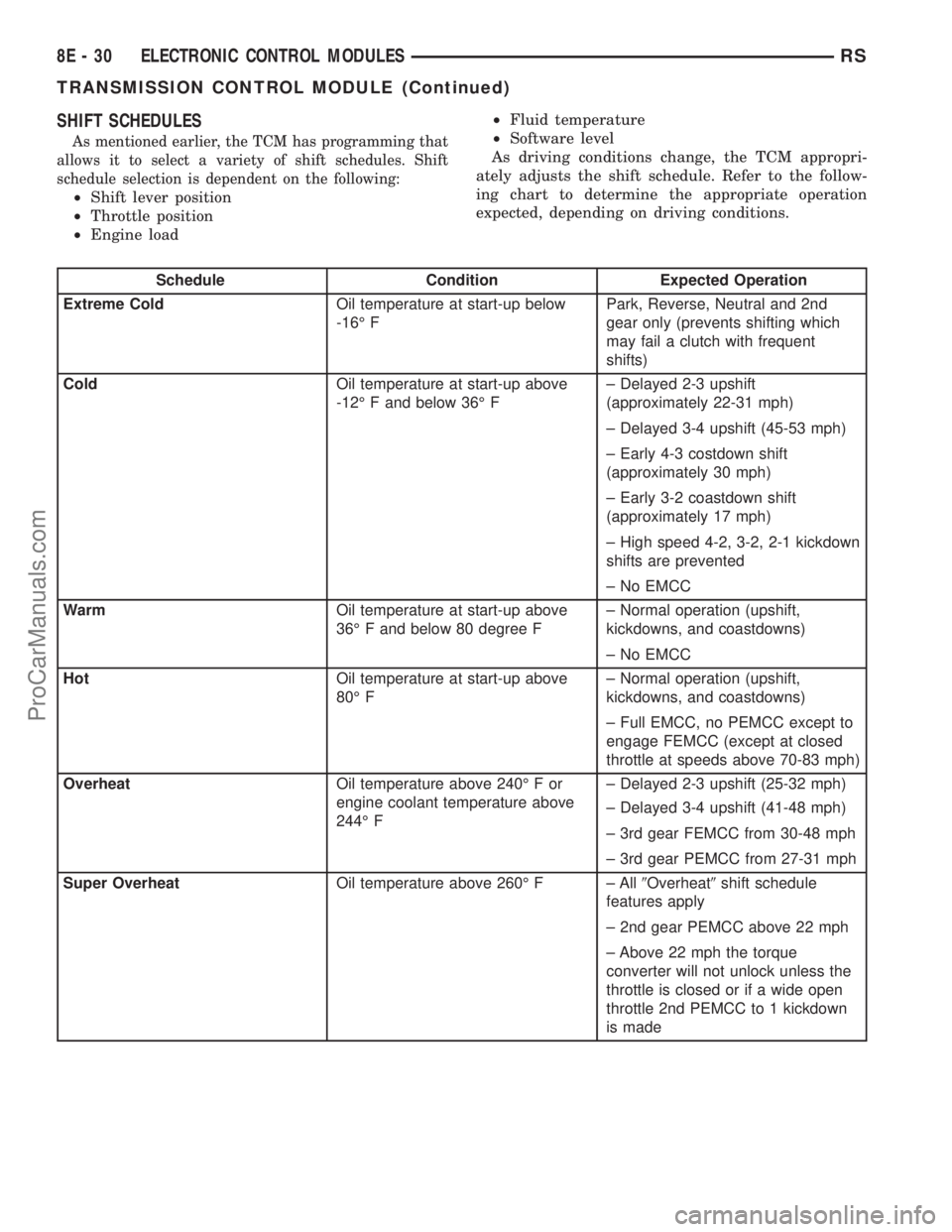
SHIFT SCHEDULES
As mentioned earlier, the TCM has programming that
allows it to select a variety of shift schedules. Shift
schedule selection is dependent on the following:
²Shift lever position
²Throttle position
²Engine load²Fluid temperature
²Software level
As driving conditions change, the TCM appropri-
ately adjusts the shift schedule. Refer to the follow-
ing chart to determine the appropriate operation
expected, depending on driving conditions.
Schedule Condition Expected Operation
Extreme ColdOil temperature at start-up below
-16É FPark, Reverse, Neutral and 2nd
gear only (prevents shifting which
may fail a clutch with frequent
shifts)
ColdOil temperature at start-up above
-12É F and below 36É F± Delayed 2-3 upshift
(approximately 22-31 mph)
± Delayed 3-4 upshift (45-53 mph)
± Early 4-3 costdown shift
(approximately 30 mph)
± Early 3-2 coastdown shift
(approximately 17 mph)
± High speed 4-2, 3-2, 2-1 kickdown
shifts are prevented
± No EMCC
WarmOil temperature at start-up above
36É F and below 80 degree F± Normal operation (upshift,
kickdowns, and coastdowns)
± No EMCC
HotOil temperature at start-up above
80É F± Normal operation (upshift,
kickdowns, and coastdowns)
± Full EMCC, no PEMCC except to
engage FEMCC (except at closed
throttle at speeds above 70-83 mph)
OverheatOil temperature above 240É F or
engine coolant temperature above
244É F± Delayed 2-3 upshift (25-32 mph)
± Delayed 3-4 upshift (41-48 mph)
± 3rd gear FEMCC from 30-48 mph
± 3rd gear PEMCC from 27-31 mph
Super OverheatOil temperature above 260É F ± All9Overheat9shift schedule
features apply
± 2nd gear PEMCC above 22 mph
± Above 22 mph the torque
converter will not unlock unless the
throttle is closed or if a wide open
throttle 2nd PEMCC to 1 kickdown
is made
8E - 30 ELECTRONIC CONTROL MODULESRS
TRANSMISSION CONTROL MODULE (Continued)
ProCarManuals.com
Page 488 of 2399
INSTRUMENT CLUSTER
TABLE OF CONTENTS
page page
INSTRUMENT CLUSTER
DESCRIPTION..........................1
OPERATION............................1
DIAGNOSIS AND TESTING
DIAGNOSIS AND TESTING - SELF-
DIAGNOSTICS.........................2
DIAGNOSIS AND TESTING - CLUSTER
DIAGNOSIS...........................2
REMOVAL.............................11
INSTALLATION.........................12CLUSTER LENS
REMOVAL.............................12
INSTALLATION.........................12
MECHANICAL TRANSMISSION RANGE
INDICATOR
REMOVAL.............................12
INSTALLATION.........................12
RED BRAKE WARNING INDICATOR
DESCRIPTION.........................13
OPERATION...........................13
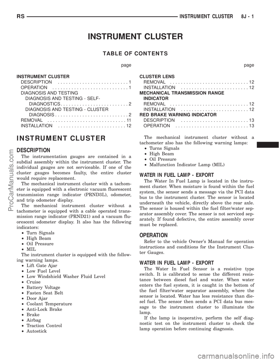
INSTRUMENT CLUSTER
DESCRIPTION
The instrumentation gauges are contained in a
subdial assembly within the instrument cluster. The
individual gauges are not serviceable. If one of the
cluster gauges becomes faulty, the entire cluster
would require replacement.
The mechanical instrument cluster with a tachom-
eter is equipped with a electronic vacuum fluorescent
transmission range indicator (PRND3L), odometer,
and trip odometer display.
The mechanical instrument cluster without a
tachometer is equipped with a cable operated trans-
mission range indicator (PRND21) and a vacuum flu-
orescent odometer display. It also has the following
indicators:
²Turn Signals
²High Beam
²Oil Pressure
²MIL
The instrument cluster is equipped with the follow-
ing warning lamps.
²Lift Gate Ajar
²Low Fuel Level
²Low Windshield Washer Fluid Level
²Cruise
²Battery Voltage
²Fasten Seat Belt
²Door Ajar
²Coolant Temperature
²Anti-Lock Brake
²Brake
²Airbag
²Traction Control
²AutostickThe mechanical instrument cluster without a
tachometer also has the following warning lamps:
²Turns Signals
²High Beam
²Oil Pressure
²Malfunction Indicator Lamp (MIL)
WATER IN FUEL LAMP - EXPORT
The Water In Fuel Lamp is located in the instru-
ment cluster. When moisture is found within the fuel
system, the sensor sends a message via the PCI data
bus to the instrument cluster. The sensor is located
underneath the vehicle, directly above the rear axle.
The sensor is housed within the fuel filter/water sep-
arator assembly cover. The sensor is not serviced sep-
arately. If found defective, the entire assembly cover
must be replaced.
OPERATION
Refer to the vehicle Owner's Manual for operation
instructions and conditions for the Instrument Clus-
ter Gauges.
WATER IN FUEL LAMP - EXPORT
The Water In Fuel Sensor is a resistive type
switch. It is calibrated to sense the different resis-
tance between diesel fuel and water. When water
enters the fuel system, it is caught in the bottom of
the fuel filter/water separator assembly, where the
sensor is located. Water has less resistance than die-
sel fuel. The sensor then sends a PCI data bus mes-
sage to the instrument cluster to illuminate the
lamp.
If the lamp is inoperative, perform the self diag-
nostic test on the instrument cluster to check the
lamp operation before continuing diagnosis.
RSINSTRUMENT CLUSTER8J-1
ProCarManuals.com
Page 495 of 2399
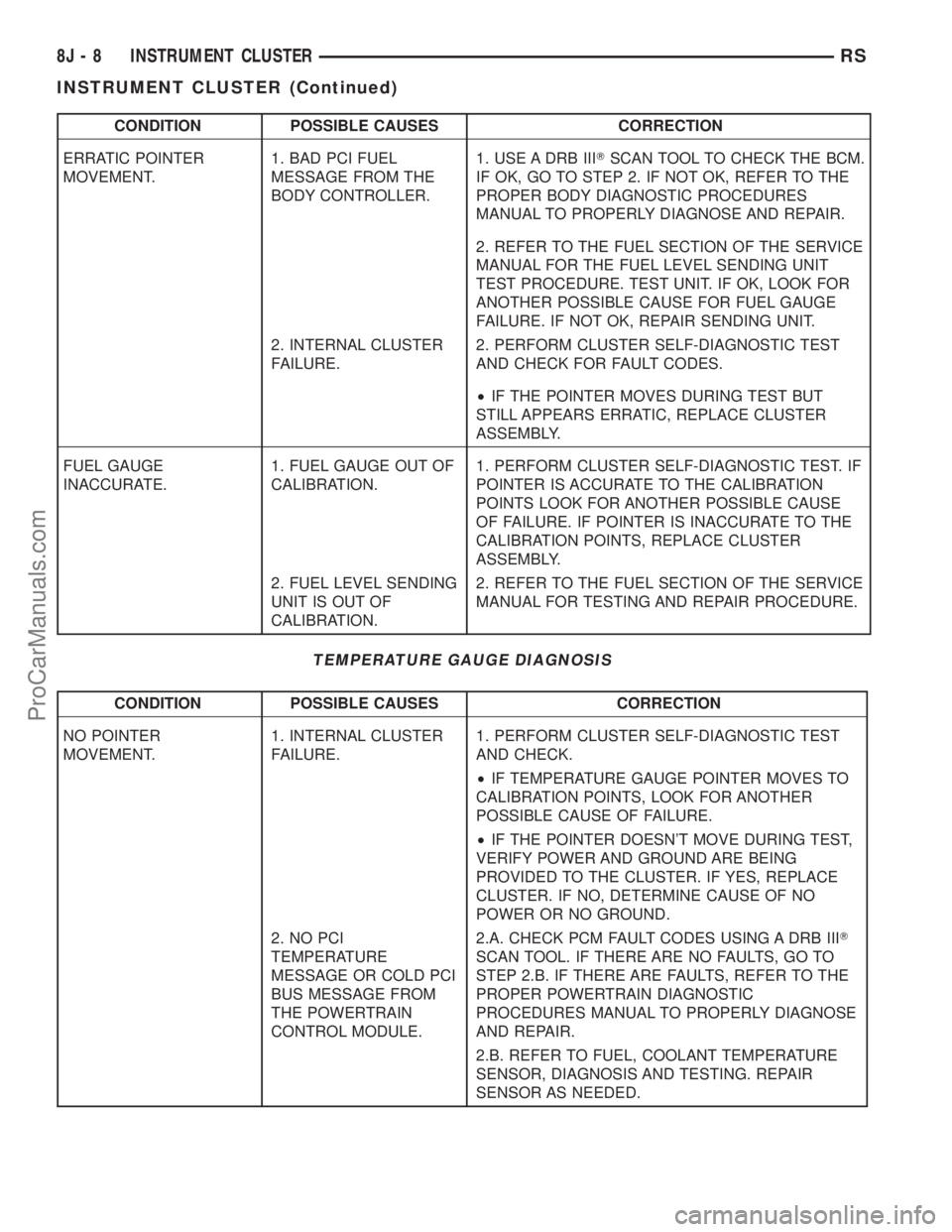
CONDITION POSSIBLE CAUSES CORRECTION
ERRATIC POINTER
MOVEMENT.1. BAD PCI FUEL
MESSAGE FROM THE
BODY CONTROLLER.1. USE A DRB IIITSCAN TOOL TO CHECK THE BCM.
IF OK, GO TO STEP 2. IF NOT OK, REFER TO THE
PROPER BODY DIAGNOSTIC PROCEDURES
MANUAL TO PROPERLY DIAGNOSE AND REPAIR.
2. REFER TO THE FUEL SECTION OF THE SERVICE
MANUAL FOR THE FUEL LEVEL SENDING UNIT
TEST PROCEDURE. TEST UNIT. IF OK, LOOK FOR
ANOTHER POSSIBLE CAUSE FOR FUEL GAUGE
FAILURE. IF NOT OK, REPAIR SENDING UNIT.
2. INTERNAL CLUSTER
FAILURE.2. PERFORM CLUSTER SELF-DIAGNOSTIC TEST
AND CHECK FOR FAULT CODES.
²IF THE POINTER MOVES DURING TEST BUT
STILL APPEARS ERRATIC, REPLACE CLUSTER
ASSEMBLY.
FUEL GAUGE
INACCURATE.1. FUEL GAUGE OUT OF
CALIBRATION.1. PERFORM CLUSTER SELF-DIAGNOSTIC TEST. IF
POINTER IS ACCURATE TO THE CALIBRATION
POINTS LOOK FOR ANOTHER POSSIBLE CAUSE
OF FAILURE. IF POINTER IS INACCURATE TO THE
CALIBRATION POINTS, REPLACE CLUSTER
ASSEMBLY.
2. FUEL LEVEL SENDING
UNIT IS OUT OF
CALIBRATION.2. REFER TO THE FUEL SECTION OF THE SERVICE
MANUAL FOR TESTING AND REPAIR PROCEDURE.
TEMPERATURE GAUGE DIAGNOSIS
CONDITION POSSIBLE CAUSES CORRECTION
NO POINTER
MOVEMENT.1. INTERNAL CLUSTER
FAILURE.1. PERFORM CLUSTER SELF-DIAGNOSTIC TEST
AND CHECK.
²IF TEMPERATURE GAUGE POINTER MOVES TO
CALIBRATION POINTS, LOOK FOR ANOTHER
POSSIBLE CAUSE OF FAILURE.
²IF THE POINTER DOESN'T MOVE DURING TEST,
VERIFY POWER AND GROUND ARE BEING
PROVIDED TO THE CLUSTER. IF YES, REPLACE
CLUSTER. IF NO, DETERMINE CAUSE OF NO
POWER OR NO GROUND.
2. NO PCI
TEMPERATURE
MESSAGE OR COLD PCI
BUS MESSAGE FROM
THE POWERTRAIN
CONTROL MODULE.2.A. CHECK PCM FAULT CODES USING A DRB IIIT
SCAN TOOL. IF THERE ARE NO FAULTS, GO TO
STEP 2.B. IF THERE ARE FAULTS, REFER TO THE
PROPER POWERTRAIN DIAGNOSTIC
PROCEDURES MANUAL TO PROPERLY DIAGNOSE
AND REPAIR.
2.B. REFER TO FUEL, COOLANT TEMPERATURE
SENSOR, DIAGNOSIS AND TESTING. REPAIR
SENSOR AS NEEDED.
8J - 8 INSTRUMENT CLUSTERRS
INSTRUMENT CLUSTER (Continued)
ProCarManuals.com
Page 676 of 2399

8W-02 COMPONENT INDEX
Component Page
A/C Compressor Clutch Relay............ 8W-42
A/C Compressor Clutch................. 8W-42
A/C- Heater Control.................... 8W-42
A/C Pressure Sensor................... 8W-42
A/C-Heater Control.................... 8W-42
Accelerator Pedal Position Sensor......... 8W-30
Accessory Relay....................... 8W-10
Adjustable Pedals Module............... 8W-30
Adjustable Pedals Switch................ 8W-30
Airbag Control Module.................. 8W-43
Ambient Temp Sensor.................. 8W-49
Antenna............................. 8W-47
Auto Shut Down Relay................. 8W-30
Auto Temp Control..................... 8W-42
Automatic Day/Night Mirror............. 8W-49
Back-Up Lamp Switch.................. 8W-51
Battery Temperature Sensor............. 8W-20
Battery............................. 8W-20
Blend Door Actuators................... 8W-42
Body Control Module................... 8W-45
Boost Pressure Sensor.................. 8W-30
B-Pillar Switches...................... 8W-61
Brake Lamp Switch................. 8W-30, 51
Brake Transmission Shift Interlock
Solenoid........................... 8W-31
Cabin Heater Assist.................... 8W-30
Camshaft Position Sensor............... 8W-30
CD Changer.......................... 8W-47
Center High Mounted Stop Lamp......... 8W-51
Cinch/Release Motors................... 8W-61
Clockspring.................. 8W-33, 41, 43, 47
Clutch Pedal Interlock Switch Jumper..... 8W-10
Clutch Pedal Interlock Switch............ 8W-10
Combination Relays.................... 8W-54
Controller Antilock Brake............... 8W-35
Crank Case Ventilation Heater........... 8W-30
Crankshaft Position Sensor.............. 8W-30
Cylinder Lock Switches................. 8W-39
Data Link Connector................... 8W-18
Diagnostic Junction Port................ 8W-18
Door Ajar Switches.................... 8W-39
Door Lock Motor/Ajar Switches........... 8W-61
Door Lock Switches.................... 8W-61
Driver Airbag......................... 8W-43
EGR Solenoid......................... 8W-30
Electric Wiper De-Icer.................. 8W-48
Engine Control Module................. 8W-30
Engine Coolant Temp Sensor............. 8W-30
Engine Oil Pressure Switch.............. 8W-30
EVAP/Purge Solenoid................... 8W-30
Evaporator Temperature Sensor.......... 8W-42
Floor Console Lamp.................... 8W-44Component Page
Fog Lamps........................... 8W-50
Front Blower Module................... 8W-42
Front Blower Motor Relay............... 8W-42
Front Blower Motor.................... 8W-42
Front Cigar Lighter.................... 8W-41
Front Control Module.................. 8W-10
Front Fog Lamp Relay.................. 8W-50
Front Intrusion Sensor................. 8W-39
Front Washer Pump Motor.............. 8W-53
Front Wiper On/Off Relay............... 8W-53
Fuel Heater.......................... 8W-30
Fuel Injectors........................ 8W-30
Fuel Pressure Solenoid................. 8W-30
Fuel Pump Module.................... 8W-30
Full Open Switches.................... 8W-61
Fuselink............................. 8W-10
Fuses............................... 8W-10
Generator............................ 8W-20
Glow Plug Relay...................... 8W-30
Glow Plugs........................... 8W-30
Grounds............................. 8W-15
Halo Lamp........................... 8W-44
Headlamp Leveling Motors.............. 8W-50
Headlamp Switch...................... 8W-50
Headlamp Washer Relay................ 8W-53
Headlamps........................... 8W-50
Heated Seat Backs..................... 8W-63
Heated Seat Cushions.................. 8W-63
Heated Seat Modules................... 8W-63
High Beam Lamps..................... 8W-50
High Note Horn....................... 8W-41
Horn Relay.......................... 8W-41
Idle Air Control Motor.................. 8W-30
Ignition Coil.......................... 8W-30
Ignition Switch....................... 8W-10
Inlet Air Temperature Sensor............ 8W-30
Instrument Cluster.................... 8W-40
Instrument Panel Switch Bank . . 8W-44, 52, 53, 63
Integrated Power Module................ 8W-10
Knock Sensor......................... 8W-30
License Lamp......................... 8W-51
Lift Pump Motor...................... 8W-30
Liftgate Ajar Switch................. 8W-39, 61
Liftgate Cinch/Release Motor............. 8W-61
Liftgate Cylinder Lock Switch............ 8W-39
Liftgate Flood Lamps................... 8W-44
Liftgate Right Pinch Sensor.............. 8W-61
Low Beam Lamps.................... 8W-50-9
Manifold Absolute Pressure Sensor........ 8W-30
Mass Air Flow Sensor.................. 8W-30
Memory Seat/Mirror Module.......... 8W-62, 63
Memory Set Switch.................... 8W-63
RS8W-02 COMPONENT INDEX8W-02-1
ProCarManuals.com
Page 852 of 2399

8W-40 INSTRUMENT CLUSTER
Component Page
Airbag Control Module................ 8W-40-2
Body Control Module....... 8W-40-2, 3, 4, 5, 6, 7,
8, 9, 10, 11
Brake Fluid Level Switch.............. 8W-40-9
Clockspring......................... 8W-40-9
Diagnostic Junction Port...... 8W-40-2, 3, 4, 5, 6,
7, 8, 9, 12
Engine Control Module........... 8W-40-8, 9, 12
Engine Coolant Temp Sensor......... 8W-40-7, 8
Engine Oil Pressure Sensor........... 8W-40-12
Engine Oil Pressure Switch........... 8W-40-12
Front Control Module................. 8W-40-9
Fuel Pump Module................... 8W-40-2
Fuse 24............................ 8W-40-2
G200..................... 8W-40-2, 10, 11, 12
G300.............................. 8W-40-9
Instrument Cluster....... 8W-40-2, 3, 4, 5, 6, 7, 8,
9, 10, 11, 12
Integrated Power Module............ 8W-40-2, 9
Left Front Door Ajar Switch............ 8W-40-3
Left Front Door Lock Motor/Ajar Switch . . . 8W-40-3
Left Sliding Door Control Module........ 8W-40-4
Left Sliding Door Latch Sensing Switch . . . 8W-40-4Component Page
Left Sliding Door Lock Motor/Ajar
Switch........................... 8W-40-4
Left Speed Control Switch............. 8W-40-9
Liftgate Ajar Switch.................. 8W-40-3
Liftgate Cinch/Release Motor........... 8W-40-3
Message Center................... 8W-40-6, 12
Multi- Function Switch................ 8W-40-6
Parking Brake Switch............. 8W-40-10, 11
Powertrain Control Module........ 8W-40-7, 9, 12
Right Front Door Ajar Switch........... 8W-40-3
Right Front Door Lock Motor/Ajar
Switch........................... 8W-40-3
Right Sliding Door Control Module....... 8W-40-5
Right Sliding Door Latch Sensing
Switch........................... 8W-40-5
Right Sliding Door Lock Motor/Ajar
Switch........................... 8W-40-5
Right Speed Control Switch............ 8W-40-9
Traction Control Switch............. 8W-40-7, 8
Transmission Control Module........... 8W-40-7
Vehicle Speed Sensor............... 8W-40-7, 8
Washer Fluid Level Switch............. 8W-40-9
RS8W-40 INSTRUMENT CLUSTER8W-40-1
ProCarManuals.com
Page 1210 of 2399
(3) Remove torque converter or clutch housing
cover and inspect rear of block for evidence of oil.
Use a black light to check for the oil leak. If a leak is
present in this area, remove transmission for further
inspection.
(a) Circular spray pattern generally indicates
seal leakage or crankshaft damage.
(b) Where leakage tends to run straight down,
possible causes are a porous block, oil gallery cup
plug, bedplate to cylinder block mating surfaces
and seal bore. See proper repair procedures for
these items.
(4) If no leaks are detected, pressurize the crank-
case as previously described.
CAUTION: Do not exceed 20.6 kPa (3 psi).
(5) If the leak is not detected, very slowly turn the
crankshaft and watch for leakage. If a leak is
detected between the crankshaft and seal while
slowly turning the crankshaft, it is possible the
crankshaft seal surface is damaged. The seal area on
the crankshaft could have minor nicks or scratches
that can be polished out with emery cloth.
CAUTION: Use extreme caution when crankshaft
polishing is necessary to remove minor nicks and
scratches. The crankshaft seal flange is especially
machined to complement the function of the rear oil
seal.
(6) For bubbles that remain steady with shaft
rotation, no further inspection can be done until dis-
assembled.
(7) After the oil leak root cause and appropriate
corrective action have been identified, replace compo-
nent(s) as necessary.
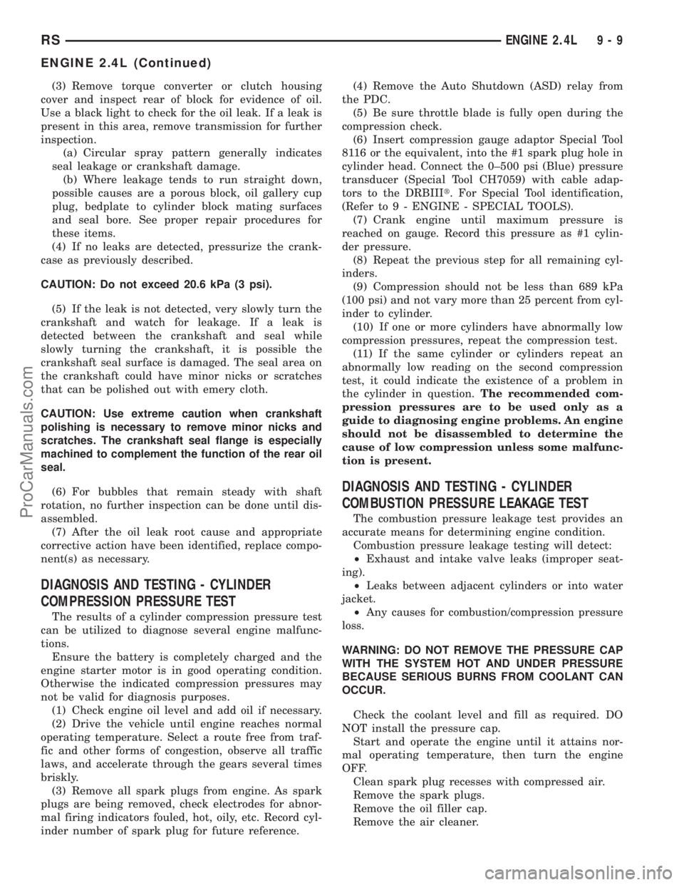
DIAGNOSIS AND TESTING - CYLINDER
COMPRESSION PRESSURE TEST
The results of a cylinder compression pressure test
can be utilized to diagnose several engine malfunc-
tions.
Ensure the battery is completely charged and the
engine starter motor is in good operating condition.
Otherwise the indicated compression pressures may
not be valid for diagnosis purposes.
(1) Check engine oil level and add oil if necessary.
(2) Drive the vehicle until engine reaches normal
operating temperature. Select a route free from traf-
fic and other forms of congestion, observe all traffic
laws, and accelerate through the gears several times
briskly.
(3) Remove all spark plugs from engine. As spark
plugs are being removed, check electrodes for abnor-
mal firing indicators fouled, hot, oily, etc. Record cyl-
inder number of spark plug for future reference.(4) Remove the Auto Shutdown (ASD) relay from
the PDC.
(5) Be sure throttle blade is fully open during the
compression check.
(6) Insert compression gauge adaptor Special Tool
8116 or the equivalent, into the #1 spark plug hole in
cylinder head. Connect the 0±500 psi (Blue) pressure
transducer (Special Tool CH7059) with cable adap-
tors to the DRBIIIt. For Special Tool identification,
(Refer to 9 - ENGINE - SPECIAL TOOLS).
(7) Crank engine until maximum pressure is
reached on gauge. Record this pressure as #1 cylin-
der pressure.
(8) Repeat the previous step for all remaining cyl-
inders.
(9) Compression should not be less than 689 kPa
(100 psi) and not vary more than 25 percent from cyl-
inder to cylinder.
(10) If one or more cylinders have abnormally low
compression pressures, repeat the compression test.
(11) If the same cylinder or cylinders repeat an
abnormally low reading on the second compression
test, it could indicate the existence of a problem in
the cylinder in question.The recommended com-
pression pressures are to be used only as a
guide to diagnosing engine problems. An engine
should not be disassembled to determine the
cause of low compression unless some malfunc-
tion is present.
DIAGNOSIS AND TESTING - CYLINDER
COMBUSTION PRESSURE LEAKAGE TEST
The combustion pressure leakage test provides an
accurate means for determining engine condition.
Combustion pressure leakage testing will detect:
²Exhaust and intake valve leaks (improper seat-
ing).
²Leaks between adjacent cylinders or into water
jacket.
²Any causes for combustion/compression pressure
loss.
WARNING: DO NOT REMOVE THE PRESSURE CAP
WITH THE SYSTEM HOT AND UNDER PRESSURE
BECAUSE SERIOUS BURNS FROM COOLANT CAN
OCCUR.
Check the coolant level and fill as required. DO
NOT install the pressure cap.
Start and operate the engine until it attains nor-
mal operating temperature, then turn the engine
OFF.
Clean spark plug recesses with compressed air.
Remove the spark plugs.
Remove the oil filler cap.
Remove the air cleaner.
RSENGINE 2.4L9-9
ENGINE 2.4L (Continued)
ProCarManuals.com
Page 1284 of 2399
(3) Remove torque converter or clutch housing
cover and inspect rear of block for evidence of oil.
Use a black light to check for the oil leak. If a leak is
present in this area, remove transmission for further
inspection.
(a) Circular spray pattern generally indicates
seal leakage or crankshaft damage.
(b) Where leakage tends to run straight down,
possible causes are a porous block, oil gallery cup
plug, bedplate to cylinder block mating surfaces
and seal bore. See proper repair procedures for
these items.
(4) If no leaks are detected, pressurize the crank-
case as previously described.
CAUTION: Do not exceed 20.6 kPa (3 psi).
(5) If the leak is not detected, very slowly turn the
crankshaft and watch for leakage. If a leak is
detected between the crankshaft and seal while
slowly turning the crankshaft, it is possible the
crankshaft seal surface is damaged. The seal area on
the crankshaft could have minor nicks or scratches
that can be polished out with emery cloth.
CAUTION: Use extreme caution when crankshaft
polishing is necessary to remove minor nicks and
scratches. The crankshaft seal flange is especially
machined to complement the function of the rear oil
seal.
(6) For bubbles that remain steady with shaft
rotation, no further inspection can be done until dis-
assembled.
(7) After the oil leak root cause and appropriate
corrective action have been identified, replace compo-
nent(s) as necessary.
DIAGNOSIS AND TESTING - CYLINDER
COMPRESSION PRESSURE TEST
The results of a cylinder compression pressure test
can be utilized to diagnose several engine malfunc-
tions.
Ensure the battery is completely charged and the
engine starter motor is in good operating condition.
Otherwise the indicated compression pressures may
not be valid for diagnosis purposes.
(1) Check engine oil level and add oil if necessary.
(2) Drive the vehicle until engine reaches normal
operating temperature. Select a route free from traf-
fic and other forms of congestion, observe all traffic
laws, and accelerate through the gears several times
briskly.
(3) Remove all spark plugs from engine. As spark
plugs are being removed, check electrodes for abnor-
mal firing indicators fouled, hot, oily, etc. Record cyl-
inder number of spark plug for future reference.(4) Remove the Auto Shutdown (ASD) relay from
the PDC.
(5) Be sure throttle blade is fully open during the
compression check.
(6) Insert compression gauge adaptor Special Tool
8116 or the equivalent, into the #1 spark plug hole in
cylinder head. Connect the 0±500 psi (Blue) pressure
transducer (Special Tool CH7059) with cable adap-
tors to the DRBIIIt. For Special Tool identification,
(Refer to 9 - ENGINE - SPECIAL TOOLS).
(7) Crank engine until maximum pressure is
reached on gauge. Record this pressure as #1 cylin-
der pressure.
(8) Repeat the previous step for all remaining cyl-
inders.
(9) Compression should not be less than 689 kPa
(100 psi) and not vary more than 25 percent from cyl-
inder to cylinder.
(10) If one or more cylinders have abnormally low
compression pressures, repeat the compression test.
(11) If the same cylinder or cylinders repeat an
abnormally low reading on the second compression
test, it could indicate the existence of a problem in
the cylinder in question.The recommended com-
pression pressures are to be used only as a
guide to diagnosing engine problems. An engine
should not be disassembled to determine the
cause of low compression unless some malfunc-
tion is present.
DIAGNOSIS AND TESTING - CYLINDER
COMBUSTION PRESSURE LEAKAGE TEST
The combustion pressure leakage test provides an
accurate means for determining engine condition.
Combustion pressure leakage testing will detect:
²Exhaust and intake valve leaks (improper seat-
ing).
²Leaks between adjacent cylinders or into water
jacket.
²Any causes for combustion/compression pressure
loss.
WARNING: DO NOT REMOVE THE PRESSURE CAP
WITH THE SYSTEM HOT AND UNDER PRESSURE
BECAUSE SERIOUS BURNS FROM COOLANT CAN
OCCUR.
Check the coolant level and fill as required. DO
NOT install the pressure cap.
Start and operate the engine until it attains nor-
mal operating temperature, then turn the engine
OFF.
Clean spark plug recesses with compressed air.
Remove the spark plugs.
Remove the oil filler cap.
Remove the air cleaner.
RSENGINE 3.3/3.8L9-83
ENGINE 3.3/3.8L (Continued)
ProCarManuals.com
Page 1292 of 2399
(20) Install the powertrain struts (Fig. 8).
(21) Install the engine rear mount bracket.
(22) Install the engine front mount and bracket
assembly.
(23)AWD equipped;Install the power transfer
unit (PTU) (Refer to 21 - TRANSMISSION/TRANS-
AXLE/POWER TRANSFER UNIT - INSTALLA-
TION).
(24) Install the axle shafts (Refer to 3 - DIFFER-
ENTIAL & DRIVELINE/HALF SHAFT - INSTALLA-
TION).(25) Connect exhaust pipe to manifold (Fig. 7).
(26) Install crossmember cradle plate (Fig. 6).
(27) Lower vehicle.
(28) Connect transaxle shift linkage.
(29) Connect transaxle electrical connectors.
(30) Remove plugs from transmission cooler hoses
and install transaxle oil cooler line service splice kit.
Refer to instructions included with kit.
(31) Install transaxle dipstick tube and attach
electrical harness clip.
(32) Connect the A/C lines to compressor.
(33)
Connect the A/C compressor electrical connector.
(34) Evacuate and recharge A/C system.
(35) Connect crankshaft and camshaft position
sensors.
(36) Connect the fuel injector electrical harness
connector and engage clip to support bracket.
(37) Connect engine coolant temperature (ECT)
sensor and ignition coil electrical connectors.
(38) Connect the ground strap to rear of cylinder
head.
(39) Install power steering reservoir.
(40) Engage wire harness clip to engine right side
mount.
(41) Connect the brake booster and speed control
vacuum hoses.
(42) Connect the vacuum hoses to the throttle
body.
(43) Connect the EGR transducer electrical connec-
tor (if equipped).
(44) Connect the TPS, IAC, and MAP sensor elec-
trical connectors.
(45) Connect throttle cables to throttle body.
(46) Install the radiator fans (Refer to 7 - COOL-
ING/ENGINE/RADIATOR FAN - INSTALLATION).
(47) Connect the radiator upper hose.
(48) Connect the heater hoses. Remove pinch-off
pliers from the rear heater hoses (if equipped).
(49) Install the radiator upper support crossmem-
ber (Refer to 23 - BODY/EXTERIOR/GRILLE OPEN-
ING REINFORCEMENT - INSTALLATION).
(50) Install the wiper module (Refer to 8 - ELEC-
TRICAL/WIPERS/WASHERS/WIPER MODULE -
INSTALLATION).
(51) Connect the fuel line to fuel rail (Refer to 14 -
FUEL SYSTEM/FUEL DELIVERY/FUEL LINES -
STANDARD PROCEDURE).
(52) Install the air cleaner and hoses.
(53) Install new oil filter. Fill engine crankcase
with proper oil to correct level.
(54) Connect negative cable to battery.
(55) Fill the cooling system (Refer to 7 - COOLING
- STANDARD PROCEDURE).
(56) Start engine and run until operating temper-
ature is reached.
(57) Adjust transmission linkage, if necessary.
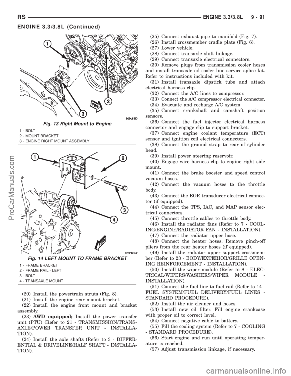
Fig. 13 Right Mount to Engine
1 - BOLT
2 - MOUNT BRACKET
3 - ENGINE RIGHT MOUNT ASSEMBLY
Fig. 14 LEFT MOUNT TO FRAME BRACKET
1 - FRAME BRACKET
2 - FRAME RAIL - LEFT
3 - BOLT
4 - TRANSAXLE MOUNT
RSENGINE 3.3/3.8L9-91
ENGINE 3.3/3.8L (Continued)
ProCarManuals.com
Page 1340 of 2399

(9) Lower vehicle and fill crankcase with specified
type and amount of engine oil. (Refer to LUBRICA-
TION & MAINTENANCE/FLUID TYPES -
DESCRIPTION)
(10) Install oil fill cap.
(11) Start engine and inspect for leaks.
(12) Stop engine and inspect oil level.
NOTE: Care should be exercised when disposing
used engine oil after it has been drained from a
vehicle engine. Refer to the WARNING listed above.
STANDARD PROCEDURE - ENGINE OIL LEVEL
CHECK
The best time to check engine oil level is after it
has sat overnight, or if the engine has been running,
allow the engine to be shut off for at least 5 minutes
before checking oil level.
Checking the oil while the vehicle is on level
ground will improve the accuracy of the oil level
reading (Fig. 102). Add only when the level is at or
below the ADD mark.
Fig. 102 Engine Oil Level Dipstick and Fill Locations
1 - COOLANT RECOVERY CONTAINER 3 - ENGINE OIL LEVEL DIPSTICK
2 - ENGINE OIL FILL CAP 4 - RADIATOR PRESSURE CAP
Fig. 101 Engine Oil Drain Plug and Oil Filter
1 - DRAIN PLUG
2 - OIL FILTER
RSENGINE 3.3/3.8L9 - 139
OIL (Continued)
ProCarManuals.com
Page 1368 of 2399

INSTALLATION
INSTALLATION - 2.5L TURBO DIESEL ENGINE
(1) Reassembly engine and transmission assembly
and install on engine cradle.
(2) Position engine and cradle assembly under
vehicle.
(3) Slowly lower the vehicle down over the engine
and cradle assembly.
(4) Install right engine mount bolts. Torque to
54N´m (40 ft. lbs.)
(5) Install left engine mount through bolt. Torque
to 75N´m (55 ft. lbs.)
(6) Raise vehicle and engine from engine cradle.
(7) Attach front engine mount bracket to lower
radiator support. Torque to 54N´m (40 ft. lbs.)
(8) Connect cabin heater coolant hose.
(9) Connect exhaust pipe to the turbocharger
downpipe flange. Torque to 28 N´m (250 in. lbs.)
(10) Connect reverse lamp electrical connector at
transmission.
(11) Connect both shifter cables (Refer to 21 -
TRANSMISSION/TRANSAXLE/MANUAL/GEAR
SHIFT CABLE - INSTALLATION).
(12) Connect the clutch slave cylinder quick dis-
connect connector (RHD only)(Refer to 6 - CLUTCH/
SLAVE CYLINDER - INSTALLATION).
(13) Install engine harness into bracket on trans-
mission.
(14) Lower vehicle.
(15) Connect fuel supply and return lines.
(16) Connect A/C lines to A/C compressor. Torque
to 23N´m (17 ft. lbs.)
(17) Route engine wiring harnes to proper location.
(18) Connect engine harness ground cables to
engine block
(19) Connect starter solenoid electrical connector
and battery feed wire to starter. Torque to 10N´m (90
in. lbs.)
(20) Connect A/C compressor, injection pump, glow
plugs, and coolant temperature sensor electrical con-
nectors.
(21) Connect generator electrical connector. Torque
to 9N´m (75 in. lbs.)
(22) Connect the fuel injector, fuel pressure sensor,
boost pressure/intake air temp sensor, cam sensor,
and egr solenoid electrical connectors (Fig. 8).
(23) Connect egr solenoid vacuum supply line to
brake boost vacuum supply line.(24) Connect brake booster vacuum supply line.
(25) Connect heater core return hose to coolant
pipe.
(26) Connect lower radiator hose to engine (Fig. 7).
(27) Install charger air cooler inlet hose (Fig. 6).
(28) Install charge air cooler outlet hose (Fig. 6).
(29) Connect upper radiator hose to engine (Fig.
7).
(30) Install battery shield.
(31) Install coolant reserve pressure container
(Refer to 7 - COOLING/ENGINE/COOLANT RECOV-
ERY PRESS CONTAINER - INSTALLATION).
(32) Install power steering reservoir and bracket
(Fig. 4).
(33) Raise vehicle
(34) Connect oil pressure sensor, oil temperature
sensor, engine speed sensor, and vehicle speed sensor
electrical connector (Fig. 9).
(35) Install suspension cradle in vehicle (Refer to
13 - FRAME & BUMPERS/FRAME/ENGINE CRA-
DLE CROSSMEMBER - INSTALLATION).
(36) Install both axle shaft assemblies (Refer to 3 -
DIFFERENTIAL & DRIVELINE/HALF SHAFT -
INSTALLATION).
(37) Connect the power steering supply, pressure,
and return lines to power steering pump (Fig. 4).
(38) Install the power steering line brackets on oil
pan (Fig. 4).
(39) Install lower splash shield and side panels.
(40) Install both front wheel and tire assemblies.
(41) Lower vehicle.
(42) Install air cleaner housing, MAF sensor, and
air intake tube assembly (Fig. 3).
(43) Refill transmission to proper level (Refer to 21
- TRANSMISSION/TRANSAXLE/MANUAL/FLUID -
STANDARD PROCEDURE).
(44) Refill engine coolant (Refer to 7 - COOLING/
ENGINE/COOLANT - STANDARD PROCEDURE).
(45) Recharge A/C system (Refer to 24 - HEATING
& AIR CONDITIONING/PLUMBING/REFRIGER-
ANT - STANDARD PROCEDURE) .
(46) Install engine cover (Refer to 9 - ENGINE -
INSTALLATION) (Fig. 2).
(47) Connect negative battery cable.
INSTALLATION - ENGINE COVER
(1) Install engine cover on engine.
(2) Install the engine cover mounting bolts (Fig.
10).
RGENGINE9a-7
ENGINE 2.5L TURBO DIESEL (Continued)
ProCarManuals.com