lock CHRYSLER CARAVAN 2002 Service Manual
[x] Cancel search | Manufacturer: CHRYSLER, Model Year: 2002, Model line: CARAVAN, Model: CHRYSLER CARAVAN 2002Pages: 2399, PDF Size: 57.96 MB
Page 1916 of 2399

STANDARD PROCEDURE - FLUID DRAIN AND
FILL
NOTE: For proper fluid change intervals, (Refer to
LUBRICATION & MAINTENANCE/MAINTENANCE
SCHEDULES - DESCRIPTION)
The fluid required in this transaxle is Mopart
ATF+4 (Automatic Transmission FluidÐType 9602).
Use of substitute fluids may result in improper
transaxle operation and/or failure.
FLUID DRAIN
(1) Raise vehicle on hoist.
(2) Remove transaxle drain plug (Fig. 127) and
drain fluid into suitable container.
(3) Install drain plug and torque to 23 N´m (17 ft.
lbs.).
FLUID FILL
(1) Remove transaxle fill plug (Fig. 128).
(2) Add 2.4-2.7L (2.5-2.9 qts.) of MopartATF+4
(Automatic Transmission FluidÐType 9602) until
fluid is within 1/8º below fill hole.
(3) Install fill plug, ensuring it is properly seated.
(4) Lower vehicle.
GEARSHIFT BOOT
REMOVAL
(1) Remove gearshift knob by pushing down and
rotating1¤4-turn clockwise (Fig. 129).
Fig. 127 Transaxle Drain Plug
1 - TRANSAXLE DRAIN PLUG
2 - DIFFERENTIAL COVER
Fig. 128 Transaxle Fill Plug
1 - FILL PLUG
2 - END COVER
Fig. 129 Gearshift Knob Removal/Installation
1 - GEARSHIFT KNOB
2 - GEARSHIFT LEVER
RST850 MANUAL TRANSAXLE21 - 359
FLUID (Continued)
ProCarManuals.com
Page 1917 of 2399

(2) Remove gearshift boot from center console by
disengaging three (3) retaining clips (Fig. 130).
INSTALLATION
(1) Install gearshift boot to console and secure
with three (3) retaining clips (Fig. 130).
(2) Install gearshift knob (Fig. 129). Orient shift
pattern
1¤4-turn clockwise, press down, and rotate1¤4-
turn counter-clockwise.
(3) Secure gearshift boot to base of knob.
GEARSHIFT CABLE -
CROSSOVER
REMOVAL
(1) Disconnect battery negative cable.
(2) Remove gearshift knob by pushing down and
rotating
1¤4-turn clock-wise (Fig. 131).
(3) Remove gearshift boot from center console by
disengaging at three (3) retaining clips (Fig. 132).
(4) Apply park brake to allow park brake handle to
clear center console upon removal.
Fig. 130 Gearshift Boot Removal/Installation
1 - GEARSHIFT BOOT
2 - CENTER CONSOLE
Fig. 131 Gearshift Knob Removal/Installation
1 - GEARSHIFT KNOB
2 - GEARSHIFT LEVER
Fig. 132 Gearshift Boot Removal/Installation
1 - GEARSHIFT BOOT
2 - CENTER CONSOLE
21 - 360 T850 MANUAL TRANSAXLERS
GEARSHIFT BOOT (Continued)
ProCarManuals.com
Page 1923 of 2399
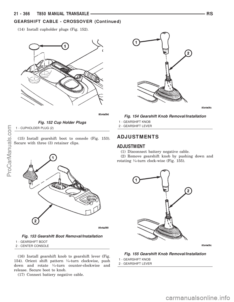
(14) Install cupholder plugs (Fig. 152).
(15) Install gearshift boot to console (Fig. 153).
Secure with three (3) retainer clips.
(16) Install gearshift knob to gearshift lever (Fig.
154). Orient shift pattern
1¤4-turn clockwise, push
down and rotate1¤4-turn counter-clockwise and
release. Secure boot to knob.
(17) Connect battery negative cable.
ADJUSTMENTS
ADJUSTMENT
(1) Disconnect battery negative cable.
(2) Remove gearshift knob by pushing down and
rotating
1¤4-turn clock-wise (Fig. 155).
Fig. 152 Cup Holder Plugs
1 - CUPHOLDER PLUG (2)
Fig. 153 Gearshift Boot Removal/Installation
1 - GEARSHIFT BOOT
2 - CENTER CONSOLE
Fig. 154 Gearshift Knob Removal/Installation
1 - GEARSHIFT KNOB
2 - GEARSHIFT LEVER
Fig. 155 Gearshift Knob Removal/Installation
1 - GEARSHIFT KNOB
2 - GEARSHIFT LEVER
21 - 366 T850 MANUAL TRANSAXLERS
GEARSHIFT CABLE - CROSSOVER (Continued)
ProCarManuals.com
Page 1925 of 2399
(9) Torque crossover lever adjustment screw to 8
N´m (70 in. lbs.).No load should be applied to
the shifter lever in any direction (hands off)
while tightening screw.
(10) Verify gearshift lever travel through all gear
ranges with engine off (not running).
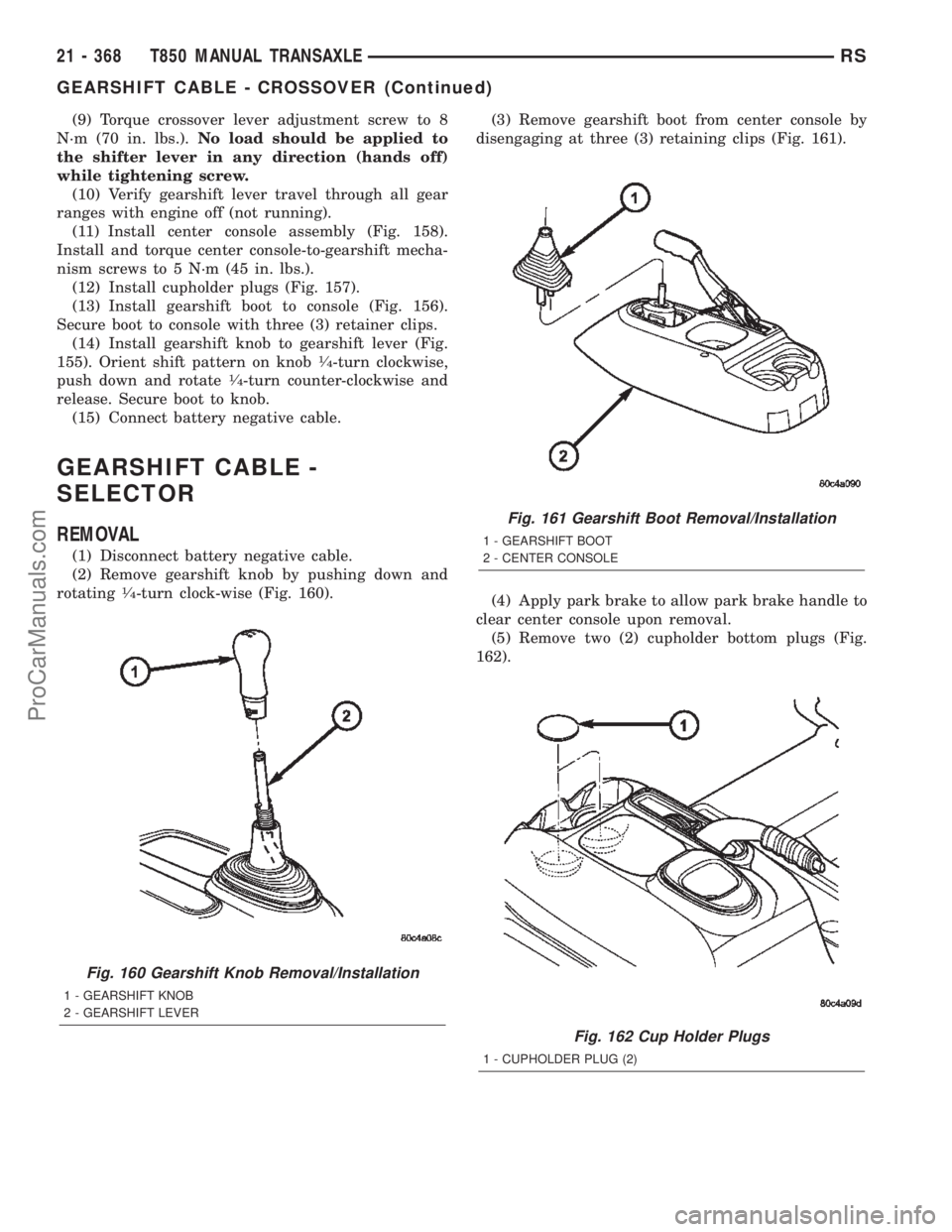
(11) Install center console assembly (Fig. 158).
Install and torque center console-to-gearshift mecha-
nism screws to 5 N´m (45 in. lbs.).
(12) Install cupholder plugs (Fig. 157).
(13) Install gearshift boot to console (Fig. 156).
Secure boot to console with three (3) retainer clips.
(14) Install gearshift knob to gearshift lever (Fig.
155). Orient shift pattern on knob
1¤4-turn clockwise,
push down and rotate1¤4-turn counter-clockwise and
release. Secure boot to knob.
(15) Connect battery negative cable.
GEARSHIFT CABLE -
SELECTOR
REMOVAL
(1) Disconnect battery negative cable.
(2) Remove gearshift knob by pushing down and
rotating
1¤4-turn clock-wise (Fig. 160).(3) Remove gearshift boot from center console by
disengaging at three (3) retaining clips (Fig. 161).
(4) Apply park brake to allow park brake handle to
clear center console upon removal.
(5) Remove two (2) cupholder bottom plugs (Fig.
162).
Fig. 160 Gearshift Knob Removal/Installation
1 - GEARSHIFT KNOB
2 - GEARSHIFT LEVER
Fig. 161 Gearshift Boot Removal/Installation
1 - GEARSHIFT BOOT
2 - CENTER CONSOLE
Fig. 162 Cup Holder Plugs
1 - CUPHOLDER PLUG (2)
21 - 368 T850 MANUAL TRANSAXLERS
GEARSHIFT CABLE - CROSSOVER (Continued)
ProCarManuals.com
Page 1931 of 2399
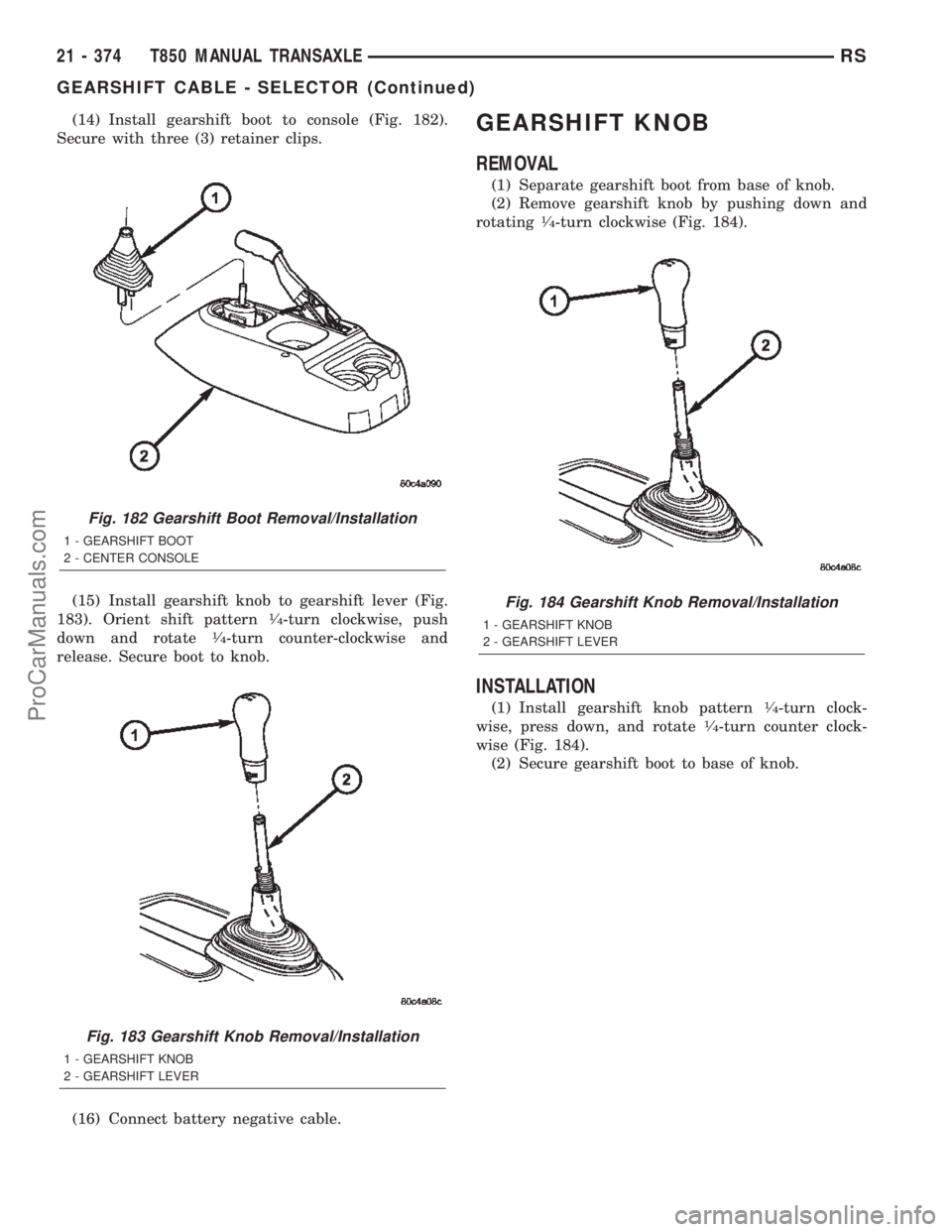
(14) Install gearshift boot to console (Fig. 182).
Secure with three (3) retainer clips.
(15) Install gearshift knob to gearshift lever (Fig.
183). Orient shift pattern
1¤4-turn clockwise, push
down and rotate1¤4-turn counter-clockwise and
release. Secure boot to knob.
(16) Connect battery negative cable.
GEARSHIFT KNOB
REMOVAL
(1) Separate gearshift boot from base of knob.
(2) Remove gearshift knob by pushing down and
rotating
1¤4-turn clockwise (Fig. 184).
INSTALLATION
(1) Install gearshift knob pattern1¤4-turn clock-
wise, press down, and rotate1¤4-turn counter clock-
wise (Fig. 184).
(2) Secure gearshift boot to base of knob.
Fig. 182 Gearshift Boot Removal/Installation
1 - GEARSHIFT BOOT
2 - CENTER CONSOLE
Fig. 183 Gearshift Knob Removal/Installation
1 - GEARSHIFT KNOB
2 - GEARSHIFT LEVER
Fig. 184 Gearshift Knob Removal/Installation
1 - GEARSHIFT KNOB
2 - GEARSHIFT LEVER
21 - 374 T850 MANUAL TRANSAXLERS
GEARSHIFT CABLE - SELECTOR (Continued)
ProCarManuals.com
Page 1932 of 2399
GEARSHIFT MECHANISM
REMOVAL
(1) Disconnect battery negative cable.
(2) Remove gearshift knob by pushing down and
rotating
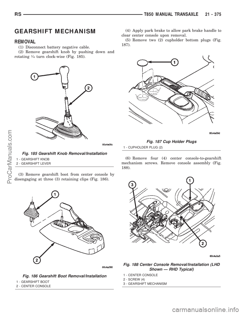
1¤4turn clock-wise (Fig. 185).
(3) Remove gearshift boot from center console by
disengaging at three (3) retaining clips (Fig. 186).(4) Apply park brake to allow park brake handle to
clear center console upon removal.
(5) Remove two (2) cupholder bottom plugs (Fig.
187).
(6) Remove four (4) center console-to-gearshift
mechanism screws. Remove console assembly (Fig.
188).
Fig. 185 Gearshift Knob Removal/Installation
1 - GEARSHIFT KNOB
2 - GEARSHIFT LEVER
Fig. 186 Gearshift Boot Removal/Installation
1 - GEARSHIFT BOOT
2 - CENTER CONSOLE
Fig. 187 Cup Holder Plugs
1 - CUPHOLDER PLUG (2)
Fig. 188 Center Console Removal/Installation (LHD
Shown Ð RHD Typical)
1 - CENTER CONSOLE
2 - SCREW (4)
3 - GEARSHIFT MECHANISM
RST850 MANUAL TRANSAXLE21 - 375
ProCarManuals.com
Page 1936 of 2399
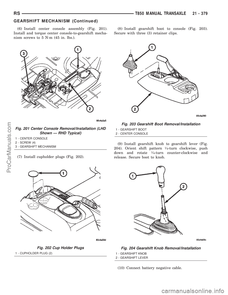
(6) Install center console assembly (Fig. 201).
Install and torque center console-to-gearshift mecha-
nism screws to 5 N´m (45 in. lbs.).
(7) Install cupholder plugs (Fig. 202).(8) Install gearshift boot to console (Fig. 203).
Secure with three (3) retainer clips.
(9) Install gearshift knob to gearshift lever (Fig.
204). Orient shift pattern
1¤4-turn clockwise, push
down and rotate1¤4-turn counter-clockwise and
release. Secure boot to knob.
(10) Connect battery negative cable.
Fig. 201 Center Console Removal/Installation (LHD
Shown Ð RHD Typical)
1 - CENTER CONSOLE
2 - SCREW (4)
3 - GEARSHIFT MECHANISM
Fig. 202 Cup Holder Plugs
1 - CUPHOLDER PLUG (2)
Fig. 203 Gearshift Boot Removal/Installation
1 - GEARSHIFT BOOT
2 - CENTER CONSOLE
Fig. 204 Gearshift Knob Removal/Installation
1 - GEARSHIFT KNOB
2 - GEARSHIFT LEVER
RST850 MANUAL TRANSAXLE21 - 379
GEARSHIFT MECHANISM (Continued)
ProCarManuals.com
Page 1939 of 2399
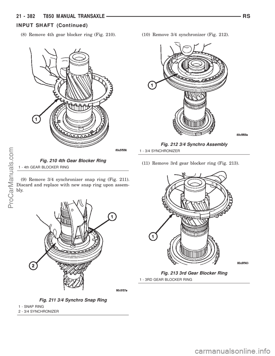
(8) Remove 4th gear blocker ring (Fig. 210).
(9) Remove 3/4 synchronizer snap ring (Fig. 211).
Discard and replace with new snap ring upon assem-
bly.(10) Remove 3/4 synchronizer (Fig. 212).
(11) Remove 3rd gear blocker ring (Fig. 213).
Fig. 210 4th Gear Blocker Ring
1 - 4th GEAR BLOCKER RING
Fig. 211 3/4 Synchro Snap Ring
1 - SNAP RING
2 - 3/4 SYNCHRONIZER
Fig. 212 3/4 Synchro Assembly
1 - 3/4 SYNCHRONIZER
Fig. 213 3rd Gear Blocker Ring
1 - 3RD GEAR BLOCKER RING
21 - 382 T850 MANUAL TRANSAXLERS
INPUT SHAFT (Continued)
ProCarManuals.com
Page 1941 of 2399
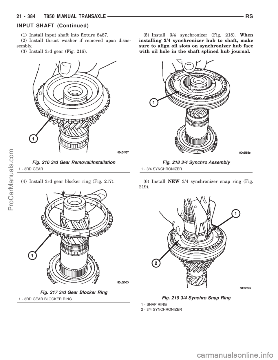
(1) Install input shaft into fixture 8487.
(2) Install thrust washer if removed upon disas-
sembly.
(3) Install 3rd gear (Fig. 216).
(4) Install 3rd gear blocker ring (Fig. 217).(5) Install 3/4 synchronizer (Fig. 218).When
installing 3/4 synchronizer hub to shaft, make
sure to align oil slots on synchronizer hub face
with oil hole in the shaft splined hub journal.
(6) InstallNEW3/4 synchronizer snap ring (Fig.
219).
Fig. 216 3rd Gear Removal/Installation
1 - 3RD GEAR
Fig. 217 3rd Gear Blocker Ring
1 - 3RD GEAR BLOCKER RING
Fig. 218 3/4 Synchro Assembly
1 - 3/4 SYNCHRONIZER
Fig. 219 3/4 Synchro Snap Ring
1 - SNAP RING
2 - 3/4 SYNCHRONIZER
21 - 384 T850 MANUAL TRANSAXLERS
INPUT SHAFT (Continued)
ProCarManuals.com
Page 1942 of 2399
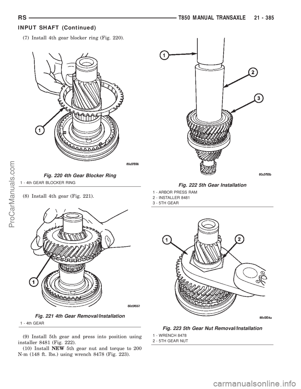
(7) Install 4th gear blocker ring (Fig. 220).
(8) Install 4th gear (Fig. 221).
(9) Install 5th gear and press into position using
installer 8481 (Fig. 222).
(10) InstallNEW5th gear nut and torque to 200
N´m (148 ft. lbs.) using wrench 8478 (Fig. 223).
Fig. 220 4th Gear Blocker Ring
1 - 4th GEAR BLOCKER RING
Fig. 221 4th Gear Removal/Installation
1 - 4th GEAR
Fig. 222 5th Gear Installation
1 - ARBOR PRESS RAM
2 - INSTALLER 8481
3 - 5TH GEAR
Fig. 223 5th Gear Nut Removal/Installation
1 - WRENCH 8478
2 - 5TH GEAR NUT
RST850 MANUAL TRANSAXLE21 - 385
INPUT SHAFT (Continued)
ProCarManuals.com