wheel CHRYSLER CARAVAN 2002 Repair Manual
[x] Cancel search | Manufacturer: CHRYSLER, Model Year: 2002, Model line: CARAVAN, Model: CHRYSLER CARAVAN 2002Pages: 2399, PDF Size: 57.96 MB
Page 119 of 2399

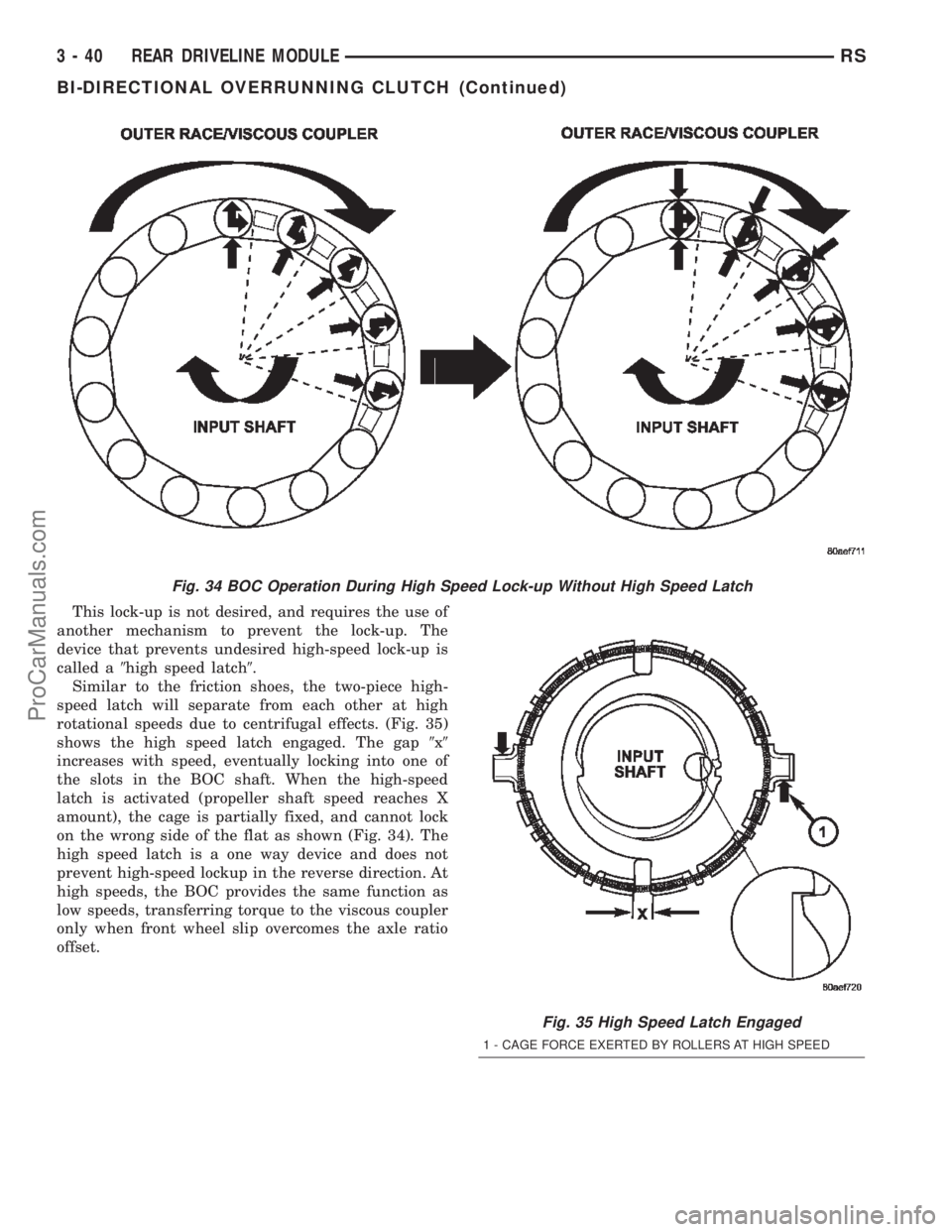
This lock-up is not desired, and requires the use of
another mechanism to prevent the lock-up. The
device that prevents undesired high-speed lock-up is
called a9high speed latch9.
Similar to the friction shoes, the two-piece high-
speed latch will separate from each other at high
rotational speeds due to centrifugal effects. (Fig. 35)
shows the high speed latch engaged. The gap9x9
increases with speed, eventually locking into one of
the slots in the BOC shaft. When the high-speed
latch is activated (propeller shaft speed reaches X
amount), the cage is partially fixed, and cannot lock
on the wrong side of the flat as shown (Fig. 34). The
high speed latch is a one way device and does not
prevent high-speed lockup in the reverse direction. At
high speeds, the BOC provides the same function as
low speeds, transferring torque to the viscous coupler
only when front wheel slip overcomes the axle ratio
offset.
Fig. 34 BOC Operation During High Speed Lock-up Without High Speed Latch
Fig. 35 High Speed Latch Engaged
1 - CAGE FORCE EXERTED BY ROLLERS AT HIGH SPEED
3 - 40 REAR DRIVELINE MODULERS
BI-DIRECTIONAL OVERRUNNING CLUTCH (Continued)
ProCarManuals.com
Page 120 of 2399

At high speed, the rollers are forced outward to the
outer race because of centrifugal force. At high
speeds, the friction shoes can no longer prevent lock-
up. When the teeth on the high-speed latch engage
into the input shaft, it keeps the rollers centered
above the flats because the tabs on the latch are
locked into the cage. (Fig. 36) shows the roller config-
uration with the High-Speed Latch engaged.
On the BOC shaft, the high speed latch teeth lock
up in the grooved areas, shown in (Fig. 37), when the
turning speed reaches the critical value. (Fig. 37)
also shows the outer race/viscous coupler. Notice the
surface (outer race) the rollers mate against when
transferring torque.
DIFFERENTIAL ASSEMBLY
DESCRIPTION
The differential gear system divides the torque
between the axle shafts. It allows the axle shafts to
rotate at different speeds when turning corners.
Each differential side gear is splined to an axle
shaft. The pinion gears are mounted on a pinion
mate shaft and are free to rotate on the shaft. The
pinion gear is fitted in a bore in the differential case
and is positioned at a right angle to the axle shafts.
OPERATION
In operation, power flow occurs as follows:
²The pinion gear rotates the ring gear²The ring gear (bolted to the differential case)
rotates the case
²The differential pinion gears (mounted on the
pinion mate shaft in the case) rotate the side gears
²The side gears (splined to the axle shafts) rotate
the shafts
During straight-ahead driving, the differential pin-
ion gears do not rotate on the pinion mate shaft. This
occurs because input torque applied to the gears is
divided and distributed equally between the two side
gears. As a result, the pinion gears revolve with the
pinion mate shaft but do not rotate around it (Fig.
38).
Fig. 36 BOC Operation at High Speed with High
Speed Latch
Fig. 37 BOC Input Shaft
1 - GROOVED AREA (2 LOCATIONS)
2 - ROLLER MATING SURFACE
Fig. 38 Differential OperationÐStraight Ahead
Driving
1 - IN STRAIGHT AHEAD DRIVING EACH WHEEL ROTATES AT
100% OF CASE SPEED
2 - PINION GEAR
3 - SIDE GEAR
4 - PINION GEARS ROTATE WITH CASE
RSREAR DRIVELINE MODULE3-41
BI-DIRECTIONAL OVERRUNNING CLUTCH (Continued)
ProCarManuals.com
Page 121 of 2399

When turning corners, the outside wheel must
travel a greater distance than the inside wheel to
complete a turn. The difference must be compensated
for to prevent the tires from scuffing and skidding
through turns. To accomplish this, the differential
allows the axle shafts to turn at unequal speeds (Fig.
39). In this instance, the input torque applied to the
pinion gears is not divided equally. The pinion gears
now rotate around the pinion mate shaft in opposite
directions. This allows the side gear and axle shaft
attached to the outside wheel to rotate at a faster
speed.
FLUID - DIFFERENTIAL
ASSEMBLY
STANDARD PROCEDURE - DIFFERENTIAL
ASSEMBLY FLUID DRAIN AND FILL
The drain plug (Fig. 40) for the differential assem-
bly is located in the bottom of the differential assem-
bly case, toward the rear of the unit.
The fill plug (Fig. 41) for the differential assembly
is located on the rear of the assembly case.
The correct fill level is to the bottom of the fill plug
hole. Be sure the vehicle is on a level surface, or is
hoisted in a level manner, in order to obtain the cor-
rect fill level.
(1) Raise the vehicle on a hoist.
(2) Position a drain pan under the differential
drain plug (Fig. 40).
(3) Remove the drain plug and allow the fluid to
drain into the pan.
(4) Install the drain plug and torque to 35 N´m (26
ft. lbs.).
(5) Re-position the drain pan under the differential
fill plug.
(6) Remove the differential fill plug (Fig. 41).
Fig. 39 Differential OperationÐOn Turns
1 - PINION GEARS ROTATE ON PINION SHAFT
Fig. 40 Differential Drain Plug
1 - DIFFERENTIAL DRAIN PLUG
Fig. 41 Differential Fill Plug
1 - DIFFERENTIAL FILL PLUG
3 - 42 REAR DRIVELINE MODULERS
DIFFERENTIAL ASSEMBLY (Continued)
ProCarManuals.com
Page 123 of 2399

VISCOUS COUPLER
DESCRIPTION
The heart of the all-wheel drive system is the
inter-axle viscous coupling and bi-directional over-
running clutch. Under normal driving the vehicle
retains predominantly front wheel drive characteris-
tics. The all-wheel drive takes effect when the front
wheels start to slip. Under normal level road,
straight line driving, 100% of the torque is allocated
to the front wheels. The viscous coupler allows more
torque to the rear wheels in accordance with the
amount of slippage at the front wheels. The variable
torque distribution is automatic with no driver
inputs required.
OPERATION
The viscous coupler (Fig. 46) is a housing nearly
filled with a high viscosity silicone liquid and thin
metal plates alternately splined to an inner and
outer drum. The viscous coupler provides torque in
the following modes:
²Shear mode (normal operation)
²Hump mode (locked mode)The inner plates are slotted around the radius and
the outer plates have holes in them. In the shear
mode (normal operation), the plates are evenly
spaced and the torque is created by the shearing of
the plates through the fluid and 90-100% of the
torque is applied to the rear axle. During the shear
mode, a fluid flow pattern is created from this design
(holes and slots). This fluid flow causes high pressure
on each side of each pair of plates and low pressure
between each pair of plates.
When a high speed difference (shear) occurs
because of loss of traction (one axle spinning faster
than the other), the silicone fluid expands as it heats
from this shearing. When the silicone expands to fill
the viscous coupler completely, this pressure differ-
ence is high enough to squeeze each pair of plates
together. The resulting hump torque is up to 8 times
higher than the shear torque. When the viscous cou-
pler is in the hump mode, it does not lock the axles
(undifferentiated 4-Wheel Drive). It controls the
amount of slippage while delivering maximum power
to the axle having greatest traction. Once the speed
difference equalizes the fluid and plates cool down
and the viscous coupler goes back to the shear mode.
3 - 44 REAR DRIVELINE MODULERS
ProCarManuals.com
Page 132 of 2399

SUPPORT PLATE - DRUM BRAKE
REMOVAL.............................64
INSTALLATION.........................64
WHEEL CYLINDERS
REMOVAL.............................65
INSPECTION..........................65
INSTALLATION.........................65
PARKING BRAKE
DESCRIPTION
DESCRIPTION........................65
DESCRIPTION - EXPORT...............66
OPERATION...........................66
STANDARD PROCEDURE
STANDARD PROCEDURE - PARKING
BRAKE AUTOMATIC ADJUSTER TENSION
RELEASE...........................66
STANDARD PROCEDURE - PARKING
BRAKE AUTOMATIC ADJUSTER TENSION
RESET.............................67
CABLES - PARKING BRAKE
REMOVAL
REMOVAL - PARKING BRAKE CABLE
(FRONT)............................67
REMOVAL - PARKING BRAKE CABLE
(INTERMEDIATE)......................68
REMOVAL - PARKING BRAKE CABLE
(RIGHT REAR)........................69
REMOVAL - PARKING BRAKE CABLE (LEFT
REAR)..............................70INSTALLATION
INSTALLATION - PARKING BRAKE CABLE
(FRONT)............................71
INSTALLATION - PARKING BRAKE CABLE
(INTERMEDIATE)......................71
INSTALLATION - PARKING BRAKE CABLE
(RIGHT REAR)........................72
INSTALLATION - PARKING BRAKE CABLE
(LEFT REAR).........................72
ADJUSTMENTS
ADJUSTMENT - PARKING BRAKE CABLES . 72
CABLES - PARKING BRAKE (EXPORT)
REMOVAL - FRONT CABLE...............72
INSTALLATION - FRONT CABLE............72
LEVER - PARKING BRAKE
REMOVAL.............................72
INSTALLATION.........................73
LEVER - PARKING BRAKE (EXPORT)
REMOVAL - PARKING BRAKE LEVER AND
FRONT CABLE.......................74
INSTALLATION - PARKING BRAKE LEVER
AND FRONT CABLE...................75
SHOES - PARKING BRAKE
REMOVAL.............................75
INSTALLATION.........................81
ADJUSTMENTS
ADJUSTMENT - PARKING BRAKE SHOES . . 83
BRAKES - BASE
DESCRIPTION
DESCRIPTION - BASE BRAKES
The base brake system consists of the following
components:
²Brake pedal
²Power brake booster
²Master cylinder
²Brake tubes and hoses
²Proportioning valve (non-ABS vehicles only)
²Disc brakes
²Drum brakes
²Brake lamp switch
²Brake fluid level switch
²Parking brakes
Front disc brakes control the braking of the front
wheels; rear braking is controlled by rear drum
brakes or rear disc brakes depending on options.
The hydraulic brake system is diagonally split on
both the non-antilock braking systems and antilock
braking systems. That means the left front and right
rear brakes are on one hydraulic circuit and the right
front and left rear are on the other.For information on the brake lamp switch, (Refer
to 8 - ELECTRICAL/LAMPS/LIGHTING - EXTERI-
OR/BRAKE LAMP SWITCH - DESCRIPTION)
Vehicles equipped with the optional antilock brake
system (ABS) use a system designated Mark 20e. It
is available with or without traction control. This
system shares most base brake hardware used on
vehicles without ABS. ABS components are described
in detail in ANTILOCK BRAKE SYSTEM.
DESCRIPTION - BASE BRAKES (EXPORT)
Four-Wheel Disc Antilock Brakes are standard on
all models.
OPERATION - BASE BRAKES
When a vehicle needs to be stopped, the driver
applies the brake pedal. The brake pedal pushes the
input rod of the power brake booster into the booster.
The booster uses vacuum to ease pedal effort as force
is transferred through the booster to the master cyl-
inder. The booster's output rod pushes in the master
cylinder's primary and secondary pistons applying
hydraulic pressure through the chassis brake tubes
to the brakes at each tire and wheel assembly.
The parking brakes are foot-operated. When
applied, the parking brake lever pulls on cables that
actuate brake shoes at each rear wheel. These shoes
RSBRAKES - BASE5-3
ProCarManuals.com
Page 134 of 2399

RED BRAKE WARNING INDICATOR LAMP
CONDITION POSSIBLE CAUSES CORRECTION
RED BRAKE WARNING
LAMP ON1. Parking brake lever not fully
released.1. Release parking brake lever.
2. Parking brake warning lamp
switch on parking brake lever.2. Inspect and replace switch as necessary.
3. Brake fluid level low in reservoir. 3. Fill reservoir. Check entire system for
leaks. Repair or replace as required.
4. Brake fluid level switch. 4. Disconnect switch wiring connector. If
lamp goes out, replace switch.
5. Mechanical instrument cluster
(MIC) problem.5. Refer to appropriate Diagnostic
information.
6. Amber ABS Warning Indicator
Lamp also illuminated.6. Refer to appropriate Diagnostic
information.
BRAKE NOISE
CONDITION POSSIBLE CAUSES CORRECTION
CLICK OR SQUAWK ON
PEDAL APPLICATION1. Brake lamp switch. 1. Replace switch.
2. Brake Transmission Shift Interlock
Linkage.2. Lubricate BTSI linkage.
3. Pedal pivot bushings 3. Lubricate pivot bushings. Replace if
necessary.
DISC BRAKE CHIRP 1. Excessive brake rotor runout. 1. Follow brake rotor diagnosis and testing.
Correct as necessary.
2. Lack of lubricant on brake caliper
slides.2. Lubricate brake caliper slides.
3. Caliper/shoes not fully seated. 3. Reseat caliper/shoes.
DISC BRAKE RATTLE OR
CLUNK1. Broken or missing anti-rattle
spring clips on shoes.1. Replace brake shoes.
2. Caliper guide pins/bolts loose. 2. Tighten guide pins/bolts.
DISC BRAKE SQUEAK AT
LOW SPEED (WHILE
APPLYING LIGHT BRAKE
PEDAL EFFORT)1. Brake shoe linings. 1. Replace brake shoes.
DRUM BRAKE CHIRP 1. Lack of lubricant on brake shoe
support plate where shoes ride.1. Lubricate shoe contact areas on brake
shoe support plates.
DRUM BRAKE CLUNK 1. Drum(s) have threaded machined
braking surface.1. Replace brake drums as necessary.
DRUM BRAKE HOWL OR
MOAN1. Lack of lubricant on brake shoe
support plate where shoes ride and
at the anchor.1. Lubricate shoe contact areas on brake
shoe support plates and at the anchor.
2. Rear brake shoes. 2. Replace rear brake shoes.
DRUM BRAKE SCRAPING
OR WHIRRING1. ABS wheel speed sensor or tone
wheel.1. Inspect, correct or replace faulty
component(s).
RSBRAKES - BASE5-5
BRAKES - BASE (Continued)
ProCarManuals.com
Page 136 of 2399

CONDITION POSSIBLE CAUSES CORRECTION
EXCESSIVE PEDAL
TRAVEL (ONE FRONT
WHEEL LOCKS UP
DURING HARD BRAKING)1. One of the two hydraulic circuits
to the front brakes is malfunctioning.1. Inspect system for leaks. Check
master cylinder for internal malfunction.
PEDAL PULSATES/
SURGES DURING
BRAKING1. Rear brake drum out of round or
disc brake rotor has excessive
thickness variation.1. Isolate condition as rear or front.
Reface or replace brake drums or
rotors as necessary.
PEDAL IS SPONGY 1. Air in brake lines. 1. Bleed brakes.
2. Power brake booster runout
(vacuum assist).2. Check booster vacuum hose and
engine tune for adequate vacuum
supply. Refer to power brake booster
diagnosis and testing.
PREMATURE REAR
WHEEL LOCKUP1. Contaminated brake shoe linings. 1. Inspect and clean, or replace shoes.
Repair source of contamination.
2. Inoperative proportioning valve
(non-ABS vehicles).2. Refer to proportioning valve
diagnosis and testing. Replace valve as
necessary.
3. Improper power brake booster
assist.3. Refer to power brake booster in the
diagnosis and testing section.
STOP/BRAKE LAMPS
S TAY O N1. Brake lamp switch out of
adjustment.1. Replace brake lamp switch.
2. Brake pedal binding. 2. Inspect and replace as necessary.
3. Obstruction in pedal linkage. 3. Remove obstruction.
4. Power Brake Booster not allowing
pedal to return completely.4. Replace power brake booster.
VEHICLE PULLS TO
RIGHT OR LEFT ON
BRAKING1. Frozen brake caliper piston. 1. Replace frozen piston or caliper.
Bleed brakes.
2. Contaminated brake shoe lining. 2. Inspect and clean, or replace shoes.
Repair source of contamination.
3. Pinched brake lines. 3. Replace pinched line.
4. Leaking piston seal. 4. Replace piston seal or brake caliper.
5. Suspension problem. 5. Refer to the Suspension group.
PARKING BRAKE -
EXCESSIVE HANDLE
TRAVEL1. Rear drum brakes or rear disc
brake parking brake shoes out of
adjustment.1. Adjust rear drum brake shoes, or
rear parking brake shoes on vehicles
with rear disc brakes.
STANDARD PROCEDURE - BASE BRAKE
BLEEDING
NOTE: This bleeding procedure is only for the vehi-
cle's base brakes hydraulic system. For bleeding
the antilock brakes hydraulic system, (Refer to 5 -
BRAKES - ABS - STANDARD PROCEDURE)CAUTION: Before removing the master cylinder
cover, thoroughly clean the cover and master cylin-
der fluid reservoir to prevent dirt and other foreign
matter from dropping into the master cylinder fluid
reservoir.
RSBRAKES - BASE5-7
BRAKES - BASE (Continued)
ProCarManuals.com
Page 137 of 2399

NOTE: The following wheel sequence should be
used when bleeding the brake hydraulic system.
The use of this wheel sequence will ensure ade-
quate removal of all trapped air from the brake
hydraulic system.
²Left Rear Wheel
²Right Front Wheel
²Right Rear Wheel
²Left Front Wheel
NOTE: When bleeding the brake system, some air
may be trapped in the brake lines or valves far
upstream, as much as ten feet from the bleeder
screw (Fig. 2). Therefore, it is essential to have a
fast flow of a large volume of brake fluid when
bleeding the brakes to ensure all the air gets out.
The brakes may be manually bled or pressure bled.
Refer to the appropriate following procedure.
MANUAL BLEEDING PROCEDURE
NOTE: Correct manual bleeding of the brakes
hydraulic system will require the aid of a helper.
NOTE: To adequately bleed the brakes using the
manual bleeding procedure the rear brakes must be
correctly adjusted. Prior to the manual bleeding of
the brake hydraulic system, correctly adjust the
rear brakes.
(1) Pump the brake pedal three or four times and
hold it down before the bleeder screw is opened.
(2) Push the brake pedal toward the floor and hold
it down. Then open the left rear bleeder screw at
least 1 full turn. When the bleeder screw opens the
brake pedal will drop all the way to the floor.CAUTION: ªJust crackingº the bleeder screw often
restricts fluid flow, allowing only a slow, weak fluid
discharge of fluid. This practice will NOT get all the
air out. Make sure the bleeder is opened at least 1
full turn when bleeding.
(3) Release the brake pedal onlyafterthe bleeder
screw is closed.
(4) Repeat steps 1 through 3, four or five times, at
each bleeder screw in the proper sequence. This
should pass a sufficient amount of fluid to expel all
the trapped air from the brake system. Be sure to
monitor the fluid level in the master cylinder, so it
stays at a proper level so air will not enter the brake
system through the master cylinder.
(5) Check pedal travel. If pedal travel is excessive
or has not been improved, enough fluid has not
passed through the system to expel all the trapped
air. Continue to bleed system as necessary.
(6) Perform a final adjustment of the rear brake
shoes (when applicable), then test drive vehicle to be
sure brakes are operating correctly and that pedal is
solid.
PRESSURE BLEEDING PROCEDURE
CAUTION: Use bleeder tank Special Tool C-3496-B
or equivalent with Adapter, Special Tool 6921, to
pressurize the hydraulic system for bleeding.
Follow pressure bleeder manufacturer's instruc-
tions for use of pressure bleeding equipment.
(1) Install the Adapter Master Cylinder Pressure
Bleed Cap, Special Tool 6921 on the fluid reservoir of
the master cylinder (Fig. 3). Attach the fluid hose
from the pressure bleeder to the fitting on Special
Tool 6921.
(2) Attach a clear plastic hose to the bleeder screw
at one wheel and feed the hose into a clear jar con-
taining fresh brake fluid.
(3) Open the left rear wheel bleeder screw at least
one full turnor more to obtain an adequate flow of
brake fluid.
CAUTION: ªJust crackingº the bleeder screw often
restricts fluid flow, allowing only a slow, weak fluid
discharge of fluid. This practice will NOT get all the
air out. Make sure the bleeder is opened at least 1
full turn when bleeding.
(4) After 4 to 8 ounces of brake fluid has been bled
through the hydraulic system, and an air-free flow is
maintained in the hose and jar, this will indicate a
good bleed of the hydraulic system has been
obtained.
(5) Repeat the procedure at all the other remain-
ing bleeder screws.
Fig. 2 Trapped Air In Brake Fluid Line
1 - TRAPPED AIR
5 - 8 BRAKES - BASERS
BRAKES - BASE (Continued)
ProCarManuals.com
Page 138 of 2399

(6) Check pedal travel. If pedal travel is excessive
or has not been improved, enough fluid has not
passed through the system to expel all the trapped
air. Be sure to monitor the fluid level in the pressure
bleeder, so it stays at a proper level so air will not
enter the brake system through the master cylinder.
(7) Perform a final adjustment of the rear brake
shoes (when applicable), then test drive vehicle to be
sure brakes are operating correctly and that pedal is
solid.
SPECIFICATIONS
BRAKE FASTENER TORQUE
DESCRIPTION N´mFt.
Lbs.In.
Lbs.
ABS ICU Mounting Bolts To
Bracket11 Ð 9 7
ABS ICU Mounting
Bracket-To-Cradle Bolts28 21 250
ABS CAB-To-HCU Mounting
Screws2Ð17
ABS Wheel Speed Sensor
Head Mounting Bolt - Front13 Ð 115
ABS Wheel Speed Sensor
Head Mounting Bolt - Rear10 Ð 90
Adjustable Pedal Position
Sensor Mounting Screws7.5 66 Ð
Adjustable Pedal Module
Mounting Screws2.0 15 Ð
DESCRIPTION N´mFt.
Lbs.In.
Lbs.
Brake Tube Nuts 17 Ð 145
Brake Hose Intermediate
Bracket Bolt12 Ð 105
Brake Hose-To-Caliper
Mounting Bolt47 35 Ð
Disc Brake Caliper Guide
Pin Bolts35 26 Ð
Disc Brake Caliper Bleeder
Screw15 Ð 125
Drum Brake Wheel Cylinder
Mounting Bolts8Ð75
Drum Brake Wheel Cylinder
Mounting Bleeder screw10 Ð 80
Drum Brake Support Plate
Mounting Bolts130 95 Ð
Junction Block (Non-ABS
Brakes) Mounting Bolts28 21 250
Master Cylinder Mounting
Nuts25 19 225
Power Brake Booster
Mounting Nuts28 21 250
Proportioning Valve
Mounting Bolts54 40 Ð
Proportioning Valve Axle
Bracket Mounting Bolt20 Ð 175
Parking Brake Lever (Pedal)
Mounting Bolts And Nut28 21 250
Wheel Mounting (Lug) Nuts 135 100 Ð
SPECIAL TOOLS
BASE BRAKE SYSTEM
Fig. 3 TOOL 6921 INSTALLED ON MASTER
CYLINDER
1 - SPECIAL TOOL 6921
2 - FLUID RESERVOIR
Tubes, Master Cylinder Bleeding 6920
RSBRAKES - BASE5-9
BRAKES - BASE (Continued)
ProCarManuals.com
Page 144 of 2399

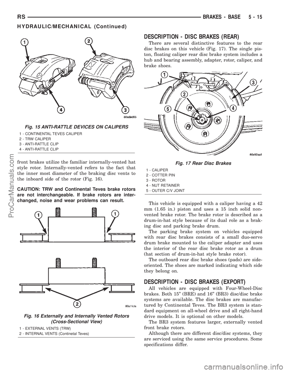
front brakes utilize the familiar internally-vented hat
style rotor. Internally-vented refers to the fact that
the inner most diameter of the braking disc vents to
the inboard side of the rotor (Fig. 16).
CAUTION: TRW and Continental Teves brake rotors
are not interchangeable. If brake rotors are inter-
changed, noise and wear problems can result.
DESCRIPTION - DISC BRAKES (REAR)
There are several distinctive features to the rear
disc brakes on this vehicle (Fig. 17). The single pis-
ton, floating caliper rear disc brake system includes a
hub and bearing assembly, adapter, rotor, caliper, and
brake shoes.
This vehicle is equipped with a caliper having a 42
mm (1.65 in.) piston and uses a 15 inch solid non-
vented brake rotor. The brake rotor is described as a
drum-in-hat style because of its dual role as a brak-
ing disc and parking brake drum.
The parking brake system on vehicles equipped
with rear disc brakes consists of a small duo-servo
drum brake mounted to the caliper adapter and uses
the interior of the rear disc brake rotor as a drum
(hat section of drum-in-hat style brake rotor).
The outboard rear disc brake shoes (pads) are side-
oriented. The shoes are marked indicating which side
they belong on.
DESCRIPTION - DISC BRAKES (EXPORT)
All vehicles are equipped with Four-Wheel-Disc
brakes. Both 15º (BRE) and 16º (BR3) disc/disc brake
systems are available. The disc brakes are manufac-
tured by Continental Teves. The BR3 system is stan-
dard equipment on all-wheel drive and all right-hand
drive models. It is optional on other models.
The BR3 system features larger, externally vented
front brake rotors.
Although there are different disc/disc systems, they
are serviced using the same service procedures. Some
specifications differ.
Fig. 15 ANTI-RATTLE DEVICES ON CALIPERS
1 - CONTINENTAL TEVES CALIPER
2 - TRW CALIPER
3 - ANTI-RATTLE CLIP
4 - ANTI-RATTLE CLIP
Fig. 16 Externally and Internally Vented Rotors
(Cross-Sectional View)
1 - EXTERNAL VENTS (TRW)
2 - INTERNAL VENTS (Continetal Teves)
Fig. 17 Rear Disc Brakes
1 - CALIPER
2 - COTTER PIN
3 - ROTOR
4 - NUT RETAINER
5 - OUTER C/V JOINT
RSBRAKES - BASE5-15
HYDRAULIC/MECHANICAL (Continued)
ProCarManuals.com