wheel bolts CHRYSLER CARAVAN 2002 Repair Manual
[x] Cancel search | Manufacturer: CHRYSLER, Model Year: 2002, Model line: CARAVAN, Model: CHRYSLER CARAVAN 2002Pages: 2399, PDF Size: 57.96 MB
Page 248 of 2399
FLYWHEEL
REMOVAL
(1) Remove transaxle assembly. (Refer to 21 -
TRANSMISSION/TRANSAXLE/MANUAL -
REMOVAL)
(2) Remove clutch pressure plate and disc. (Refer
to 6 - CLUTCH/CLUTCH DISC - REMOVAL)
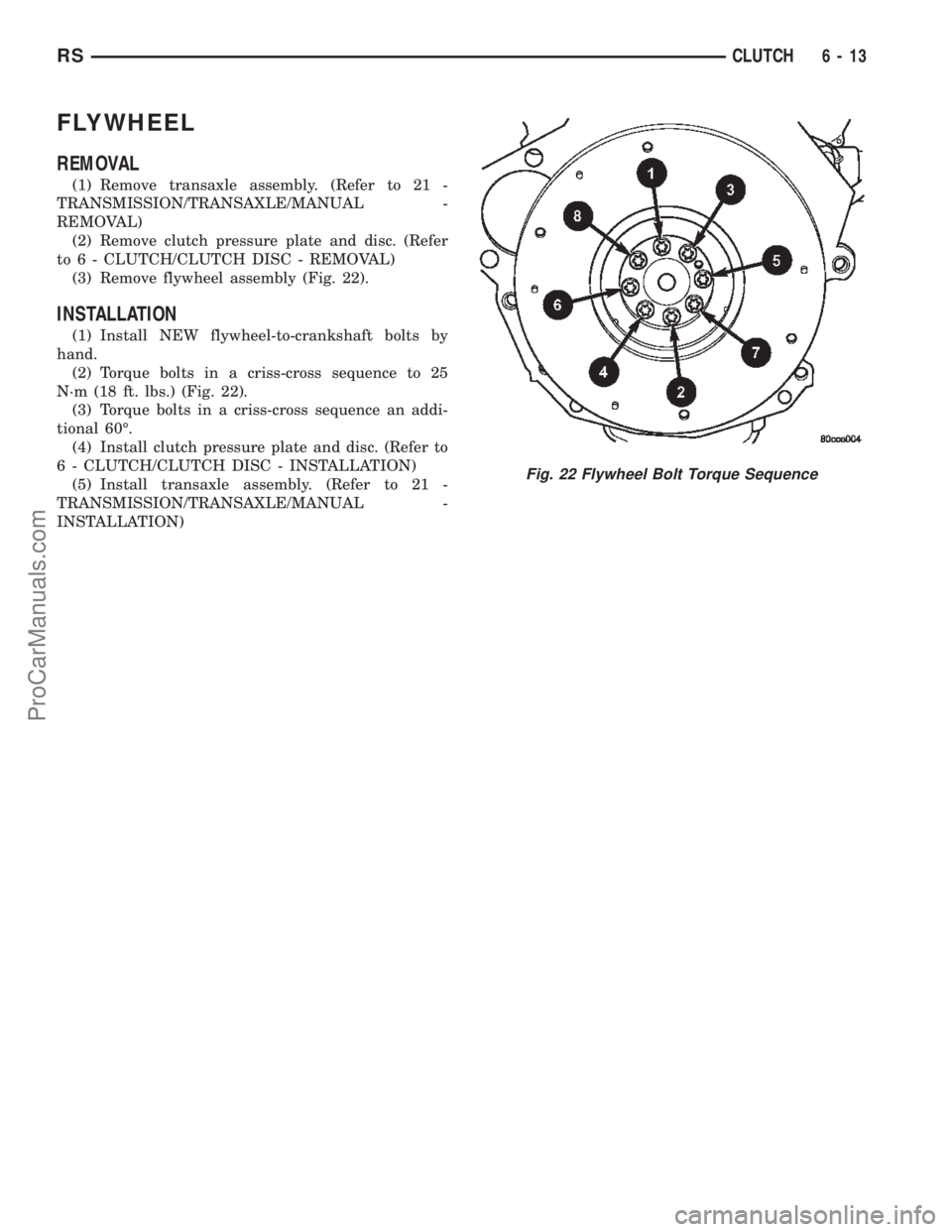
(3) Remove flywheel assembly (Fig. 22).
INSTALLATION
(1) Install NEW flywheel-to-crankshaft bolts by
hand.
(2) Torque bolts in a criss-cross sequence to 25
N´m (18 ft. lbs.) (Fig. 22).
(3) Torque bolts in a criss-cross sequence an addi-
tional 60É.
(4) Install clutch pressure plate and disc. (Refer to
6 - CLUTCH/CLUTCH DISC - INSTALLATION)
(5) Install transaxle assembly. (Refer to 21 -
TRANSMISSION/TRANSAXLE/MANUAL -
INSTALLATION)
Fig. 22 Flywheel Bolt Torque Sequence
RSCLUTCH6-13
ProCarManuals.com
Page 411 of 2399
REMOVAL - 3.3/3.8L
(1) Release hood latch and open hood.
(2) Disconnect and isolate the battery negative
cable.
(3) Hoist and support vehicle on safety stands.
(4) Remove nut holding B+ terminal to starter
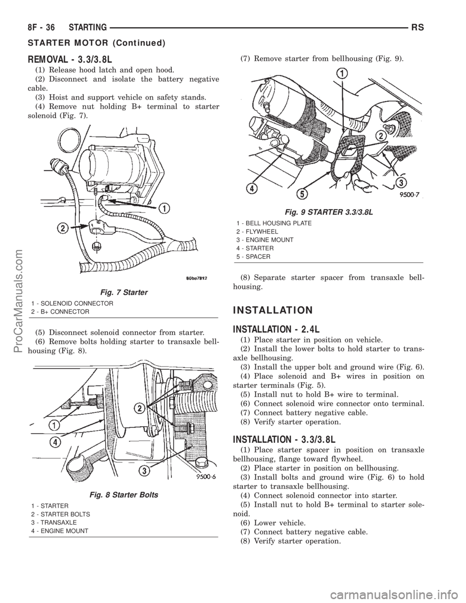
solenoid (Fig. 7).
(5) Disconnect solenoid connector from starter.
(6) Remove bolts holding starter to transaxle bell-
housing (Fig. 8).(7) Remove starter from bellhousing (Fig. 9).
(8) Separate starter spacer from transaxle bell-
housing.
INSTALLATION
INSTALLATION - 2.4L
(1) Place starter in position on vehicle.
(2) Install the lower bolts to hold starter to trans-
axle bellhousing.
(3) Install the upper bolt and ground wire (Fig. 6).
(4) Place solenoid and B+ wires in position on
starter terminals (Fig. 5).
(5) Install nut to hold B+ wire to terminal.
(6) Connect solenoid wire connector onto terminal.
(7) Connect battery negative cable.
(8) Verify starter operation.
INSTALLATION - 3.3/3.8L
(1) Place starter spacer in position on transaxle
bellhousing, flange toward flywheel.
(2) Place starter in position on bellhousing.
(3) Install bolts and ground wire (Fig. 6) to hold
starter to transaxle bellhousing.
(4) Connect solenoid connector into starter.
(5) Install nut to hold B+ terminal to starter sole-
noid.
(6) Lower vehicle.
(7) Connect battery negative cable.
(8) Verify starter operation.
Fig. 7 Starter
1 - SOLENOID CONNECTOR
2 - B+ CONNECTOR
Fig. 8 Starter Bolts
1-STARTER
2 - STARTER BOLTS
3 - TRANSAXLE
4 - ENGINE MOUNT
Fig. 9 STARTER 3.3/3.8L
1 - BELL HOUSING PLATE
2 - FLYWHEEL
3 - ENGINE MOUNT
4-STARTER
5 - SPACER
8F - 36 STARTINGRS
STARTER MOTOR (Continued)
ProCarManuals.com
Page 437 of 2399
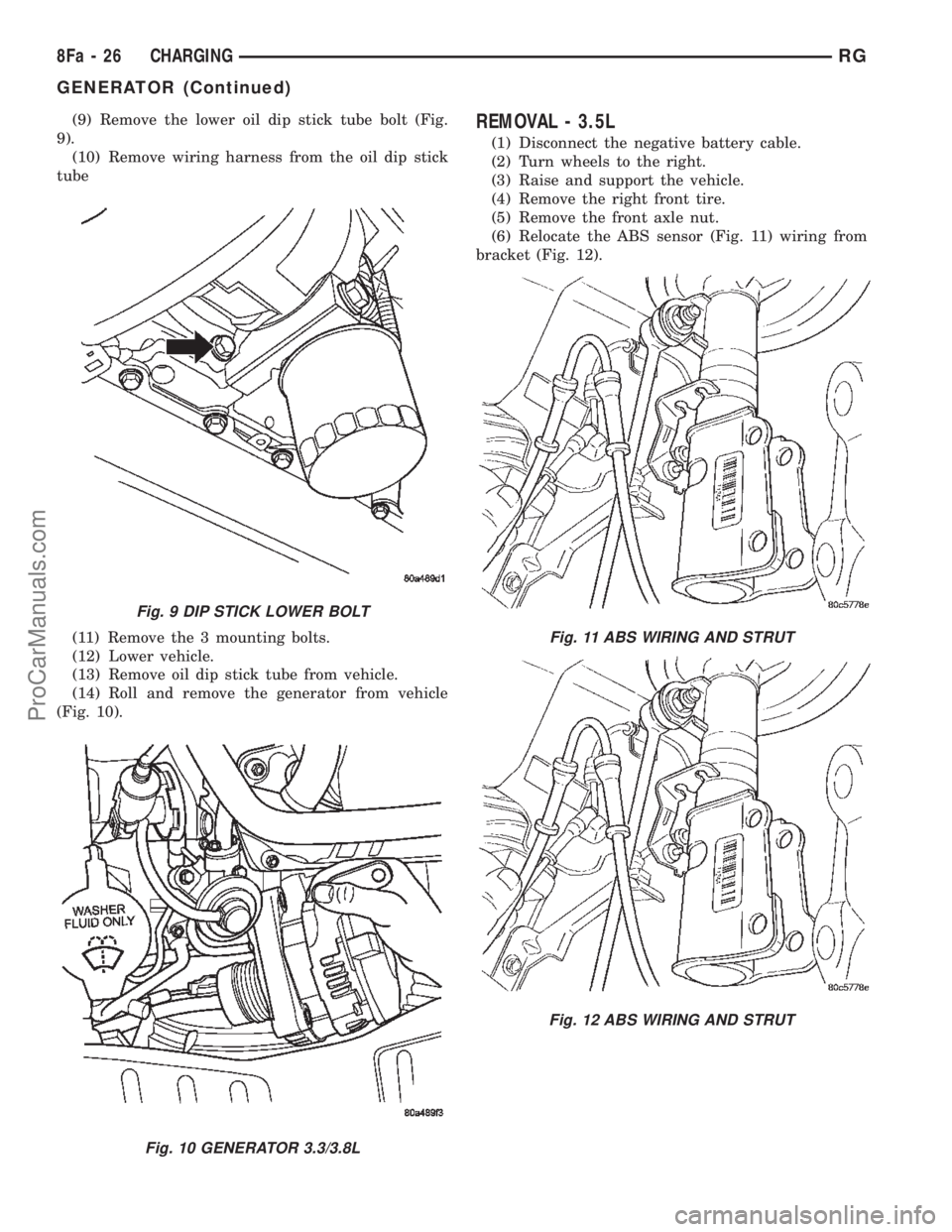
(9) Remove the lower oil dip stick tube bolt (Fig.
9).
(10) Remove wiring harness from the oil dip stick
tube
(11) Remove the 3 mounting bolts.
(12) Lower vehicle.
(13) Remove oil dip stick tube from vehicle.
(14) Roll and remove the generator from vehicle
(Fig. 10).REMOVAL - 3.5L
(1) Disconnect the negative battery cable.
(2) Turn wheels to the right.
(3) Raise and support the vehicle.
(4) Remove the right front tire.
(5) Remove the front axle nut.
(6) Relocate the ABS sensor (Fig. 11) wiring from
bracket (Fig. 12).
Fig. 9 DIP STICK LOWER BOLT
Fig. 10 GENERATOR 3.3/3.8L
Fig. 11 ABS WIRING AND STRUT
Fig. 12 ABS WIRING AND STRUT
8Fa - 26 CHARGINGRG
GENERATOR (Continued)
ProCarManuals.com
Page 439 of 2399
(5) Connect the push-in field wire connector to
back of generator.
(6) Install the EVAP Purge solenoid to its bracket.
(7) Install the Air Box, refer to the Engine/Air
Cleaner for more information.
(8) Connect the Inlet Air Temperature sensor.
(9) Connect battery negative cable.
INSTALLATION - 2.5L
(1) Install generator.
(2) Install the 2 lower mounting Bolts (Fig. 8).
(3) Install the Air Cleaner Box (Fig. 7).
(4) Install the upper support bracket (Fig. 6).
(5) Install the wiring harness on upper generator
bracket (Fig. 6).
(6) Connect the field connection (Fig. 5).
(7) Connect the generator battery connection (Fig.
5).
(8) Raise vehicle and support.
(9) Install the generator drive belt (Fig. 4).
(10) Install the right front splash shield (Fig. 3).
(11) Lower vehicle.
(12) Install the engine cover (Fig. 2).
(13) Connect the negative battery cable (Fig. 1).
INSTALLATION - 3.3/3.8L
(1) Roll and place generator in position on vehicle
(Fig. 10).
(2) Install upper bolts to hold generator in place.
(3) Lubricate the o-ring. Install oil dip stick tube.
(4) Install the upper oil dip stick tube bolt.
(5) Place B+ terminal in position on generator.
(6) Install nut to hold B+ wire terminal to back of
generator.
(7) Connect the push-in field wire connector into
back of generator.
(8) Raise vehicle and support.
(9) Install the lower mounting bolt and tighten.
(10) Install the lower oil dip stick tube bolt and
tighten (Fig. 9).
(11) Install accessory drive belt, refer to the Cool-
ing System section for proper procedures.
(12) Install the right front lower splash shield.
(13) Lower vehicle.
(14) Install wiring harness to the oil dip stick tube
(15) Connect battery negative cable.
(16) Verify generator output rate.
INSTALLATION - 3.5L
(1) Install generator (Fig. 16) and the 3 mounting
bolts and tighten.
(2) Connect the generator positive battery cable
(Fig. 15).
(3) Connect the field connector and lock the con-
nector (Fig. 15).
(4) Install the axle shaft to the transmission.(5) Install axle to steering knuckle (Fig. 13).
(6) Install the 2 upper clevies bolts and tighten,
refer to the Suspension section.
(7) Install axle nut and tighten, refer to the Differ-
ential and Driveline section.
(8) Relocate the ABS sensor wiring to bracket (Fig.
12).
(9) Install the accessory drive belt (Fig. 14), refer
to the Cooling section.
(10) Install the right front splash shield.
(11) Install the right front tire, refer to the Wheels
and Tires section.
(12) Lower vehicle.
(13) Connect the negative battery cable.
GENERATOR DECOUPLER
PULLEY
DESCRIPTION
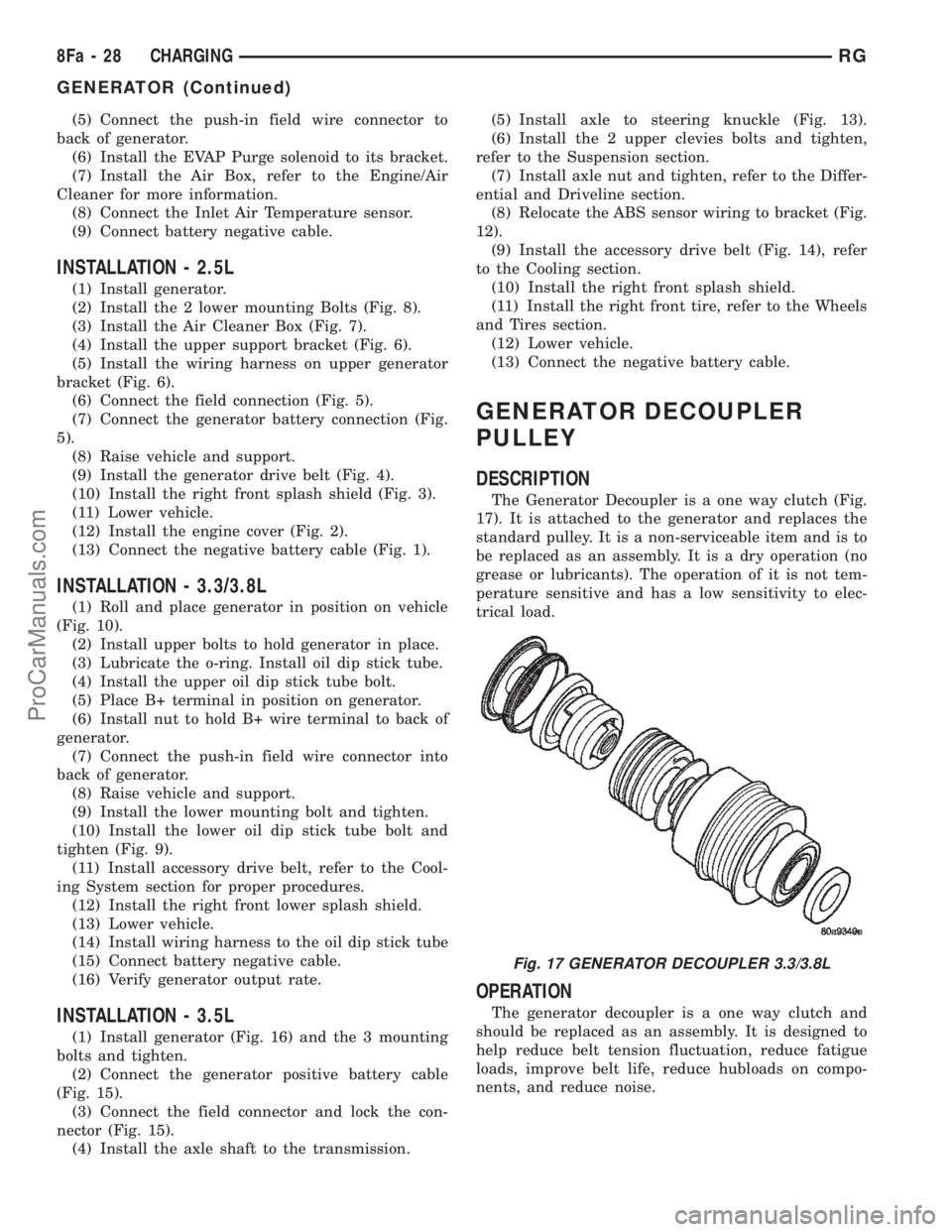
The Generator Decoupler is a one way clutch (Fig.
17). It is attached to the generator and replaces the
standard pulley. It is a non-serviceable item and is to
be replaced as an assembly. It is a dry operation (no
grease or lubricants). The operation of it is not tem-
perature sensitive and has a low sensitivity to elec-
trical load.
OPERATION
The generator decoupler is a one way clutch and
should be replaced as an assembly. It is designed to
help reduce belt tension fluctuation, reduce fatigue
loads, improve belt life, reduce hubloads on compo-
nents, and reduce noise.
Fig. 17 GENERATOR DECOUPLER 3.3/3.8L
8Fa - 28 CHARGINGRG
GENERATOR (Continued)
ProCarManuals.com
Page 450 of 2399
REMOVAL - 3.3/3.8L
(1) Release hood latch and open hood.
(2) Disconnect and isolate the battery negative
cable.
(3) Hoist and support vehicle on safety stands.
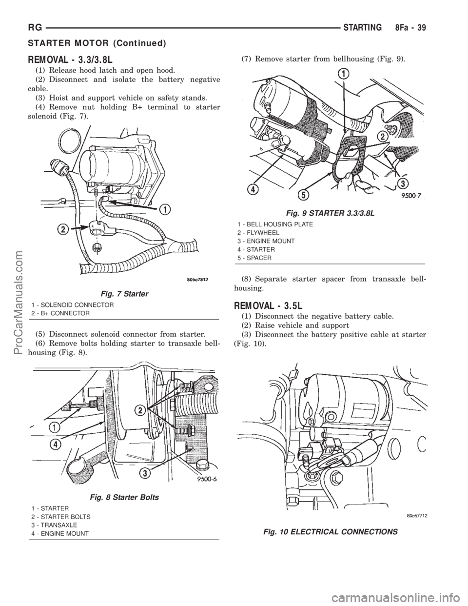
(4) Remove nut holding B+ terminal to starter
solenoid (Fig. 7).
(5) Disconnect solenoid connector from starter.
(6) Remove bolts holding starter to transaxle bell-
housing (Fig. 8).(7) Remove starter from bellhousing (Fig. 9).
(8) Separate starter spacer from transaxle bell-
housing.
REMOVAL - 3.5L
(1) Disconnect the negative battery cable.
(2) Raise vehicle and support
(3) Disconnect the battery positive cable at starter
(Fig. 10).
Fig. 7 Starter
1 - SOLENOID CONNECTOR
2 - B+ CONNECTOR
Fig. 8 Starter Bolts
1-STARTER
2 - STARTER BOLTS
3 - TRANSAXLE
4 - ENGINE MOUNT
Fig. 9 STARTER 3.3/3.8L
1 - BELL HOUSING PLATE
2 - FLYWHEEL
3 - ENGINE MOUNT
4-STARTER
5 - SPACER
Fig. 10 ELECTRICAL CONNECTIONS
RGSTARTING8Fa-39
STARTER MOTOR (Continued)
ProCarManuals.com
Page 451 of 2399
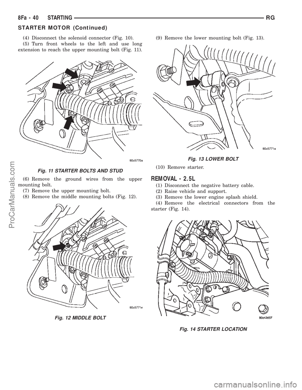
(4) Disconnect the solenoid connector (Fig. 10).
(5) Turn front wheels to the left and use long
extension to reach the upper mounting bolt (Fig. 11).
(6) Remove the ground wires from the upper
mounting bolt.
(7) Remove the upper mounting bolt.
(8) Remove the middle mounting bolts (Fig. 12).(9) Remove the lower mounting bolt (Fig. 13).
(10) Remove starter.
REMOVAL - 2.5L
(1) Disconnect the negative battery cable.
(2) Raise vehicle and support.
(3) Remove the lower engine splash shield.
(4) Remove the electrical connectors from the
starter (Fig. 14).
Fig. 11 STARTER BOLTS AND STUD
Fig. 12 MIDDLE BOLT
Fig. 13 LOWER BOLT
Fig. 14 STARTER LOCATION
8Fa - 40 STARTINGRG
STARTER MOTOR (Continued)
ProCarManuals.com
Page 452 of 2399
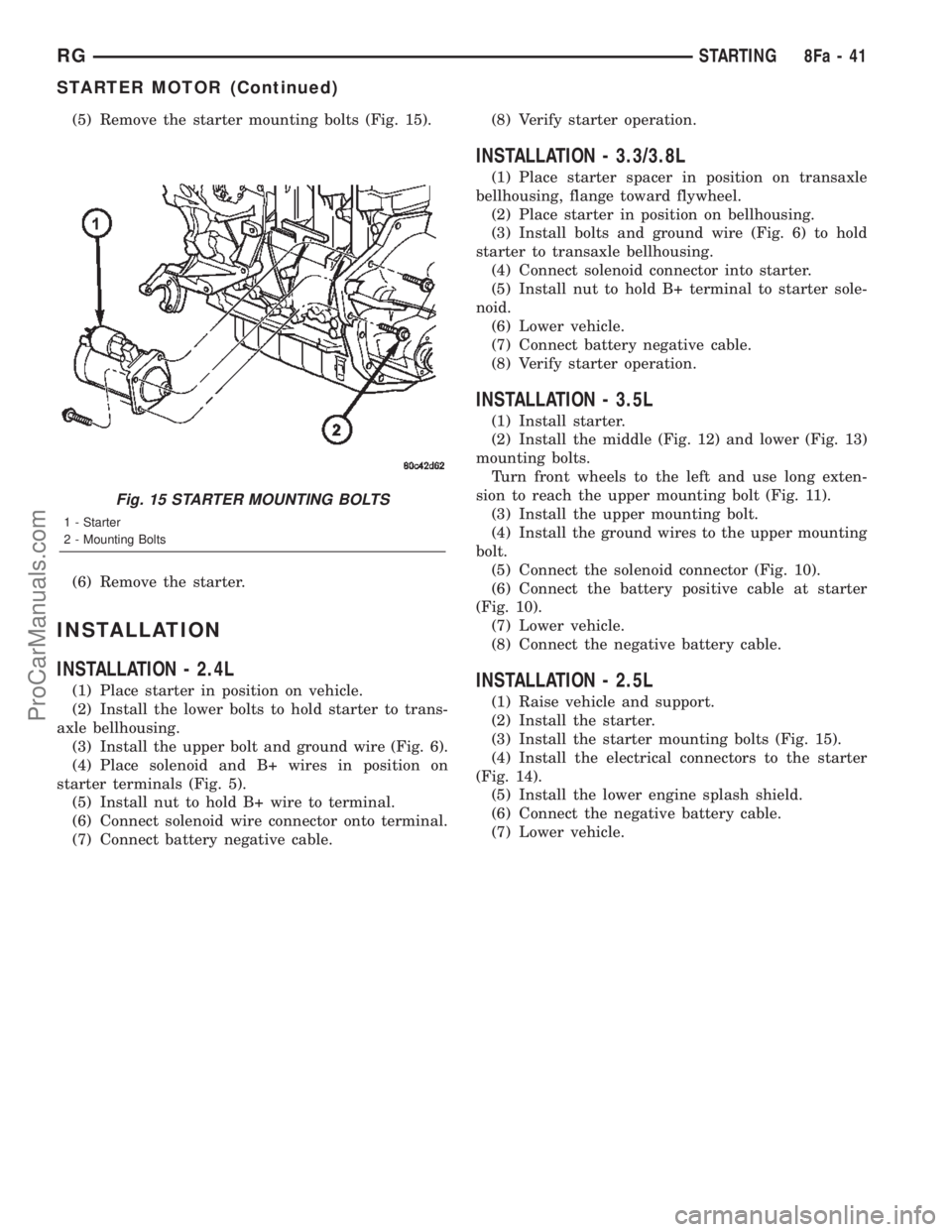
(5) Remove the starter mounting bolts (Fig. 15).
(6) Remove the starter.
INSTALLATION
INSTALLATION - 2.4L
(1) Place starter in position on vehicle.
(2) Install the lower bolts to hold starter to trans-
axle bellhousing.
(3) Install the upper bolt and ground wire (Fig. 6).
(4) Place solenoid and B+ wires in position on
starter terminals (Fig. 5).
(5) Install nut to hold B+ wire to terminal.
(6) Connect solenoid wire connector onto terminal.
(7) Connect battery negative cable.(8) Verify starter operation.
INSTALLATION - 3.3/3.8L
(1) Place starter spacer in position on transaxle
bellhousing, flange toward flywheel.
(2) Place starter in position on bellhousing.
(3) Install bolts and ground wire (Fig. 6) to hold
starter to transaxle bellhousing.
(4) Connect solenoid connector into starter.
(5) Install nut to hold B+ terminal to starter sole-
noid.
(6) Lower vehicle.
(7) Connect battery negative cable.
(8) Verify starter operation.
INSTALLATION - 3.5L
(1) Install starter.
(2) Install the middle (Fig. 12) and lower (Fig. 13)
mounting bolts.
Turn front wheels to the left and use long exten-
sion to reach the upper mounting bolt (Fig. 11).
(3) Install the upper mounting bolt.
(4) Install the ground wires to the upper mounting
bolt.
(5) Connect the solenoid connector (Fig. 10).
(6) Connect the battery positive cable at starter
(Fig. 10).
(7) Lower vehicle.
(8) Connect the negative battery cable.
INSTALLATION - 2.5L
(1) Raise vehicle and support.
(2) Install the starter.
(3) Install the starter mounting bolts (Fig. 15).
(4) Install the electrical connectors to the starter
(Fig. 14).
(5) Install the lower engine splash shield.
(6) Connect the negative battery cable.
(7) Lower vehicle.
Fig. 15 STARTER MOUNTING BOLTS
1 - Starter
2 - Mounting Bolts
RGSTARTING8Fa-41
STARTER MOTOR (Continued)
ProCarManuals.com
Page 483 of 2399
INSTALLATION - 3.3/3.8L
(1) Install coil over studs on bracket.
(2) Install 2 bolts to ignition coil.
(3) Install 2 nuts to the ignition coil studs. Tighten
nuts and bolts.
(4) Connect the electrical connector to the ignition
coil.
(5) Install the ignition cables to the ignition coil.
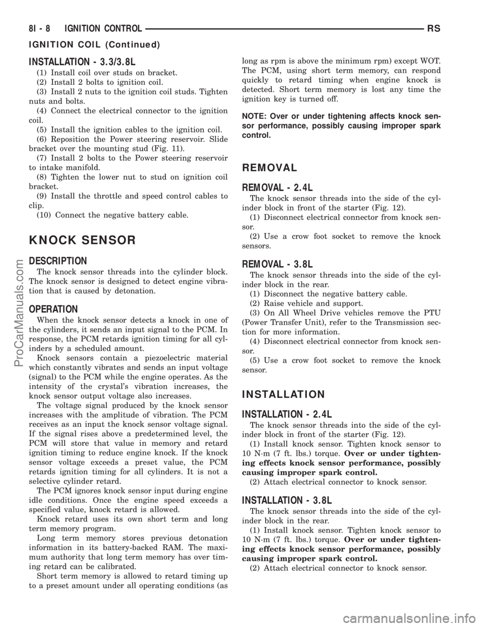
(6) Reposition the Power steering reservoir. Slide
bracket over the mounting stud (Fig. 11).
(7) Install 2 bolts to the Power steering reservoir
to intake manifold.
(8) Tighten the lower nut to stud on ignition coil
bracket.
(9) Install the throttle and speed control cables to
clip.
(10) Connect the negative battery cable.
KNOCK SENSOR
DESCRIPTION
The knock sensor threads into the cylinder block.
The knock sensor is designed to detect engine vibra-
tion that is caused by detonation.
OPERATION
When the knock sensor detects a knock in one of
the cylinders, it sends an input signal to the PCM. In
response, the PCM retards ignition timing for all cyl-
inders by a scheduled amount.
Knock sensors contain a piezoelectric material
which constantly vibrates and sends an input voltage
(signal) to the PCM while the engine operates. As the
intensity of the crystal's vibration increases, the
knock sensor output voltage also increases.
The voltage signal produced by the knock sensor
increases with the amplitude of vibration. The PCM
receives as an input the knock sensor voltage signal.
If the signal rises above a predetermined level, the
PCM will store that value in memory and retard
ignition timing to reduce engine knock. If the knock
sensor voltage exceeds a preset value, the PCM
retards ignition timing for all cylinders. It is not a
selective cylinder retard.
The PCM ignores knock sensor input during engine
idle conditions. Once the engine speed exceeds a
specified value, knock retard is allowed.
Knock retard uses its own short term and long
term memory program.
Long term memory stores previous detonation
information in its battery-backed RAM. The maxi-
mum authority that long term memory has over tim-
ing retard can be calibrated.
Short term memory is allowed to retard timing up
to a preset amount under all operating conditions (aslong as rpm is above the minimum rpm) except WOT.
The PCM, using short term memory, can respond
quickly to retard timing when engine knock is
detected. Short term memory is lost any time the
ignition key is turned off.
NOTE: Over or under tightening affects knock sen-
sor performance, possibly causing improper spark
control.
REMOVAL
REMOVAL - 2.4L
The knock sensor threads into the side of the cyl-
inder block in front of the starter (Fig. 12).
(1) Disconnect electrical connector from knock sen-
sor.
(2) Use a crow foot socket to remove the knock
sensors.
REMOVAL - 3.8L
The knock sensor threads into the side of the cyl-
inder block in the rear.
(1) Disconnect the negative battery cable.
(2) Raise vehicle and support.
(3) On All Wheel Drive vehicles remove the PTU
(Power Transfer Unit), refer to the Transmission sec-
tion for more information.
(4) Disconnect electrical connector from knock sen-
sor.
(5) Use a crow foot socket to remove the knock
sensor.
INSTALLATION
INSTALLATION - 2.4L
The knock sensor threads into the side of the cyl-
inder block in front of the starter (Fig. 12).
(1) Install knock sensor. Tighten knock sensor to
10 N´m (7 ft. lbs.) torque.Over or under tighten-
ing effects knock sensor performance, possibly
causing improper spark control.
(2) Attach electrical connector to knock sensor.
INSTALLATION - 3.8L
The knock sensor threads into the side of the cyl-
inder block in the rear.
(1) Install knock sensor. Tighten knock sensor to
10 N´m (7 ft. lbs.) torque.Over or under tighten-
ing effects knock sensor performance, possibly
causing improper spark control.
(2) Attach electrical connector to knock sensor.
8I - 8 IGNITION CONTROLRS
IGNITION COIL (Continued)
ProCarManuals.com
Page 614 of 2399
(2) Remove the driver airbag from the steering
wheel (Refer to 8 - ELECTRICAL/RESTRAINTS/
DRIVER AIRBAG - REMOVAL).
(3) Remove the plastic wire retainer that captures
the horn switch feed pigtail wire between the upper
left inflator stud and the inflator on the back of the
driver airbag housing.
(4) Remove the four nuts that secure the upper
and lower trim cover retainers to the studs on the
back of the driver airbag housing.
(5) Remove the upper and lower trim cover retain-
ers from the airbag housing studs.
(6) Remove the horn switch ground pigtail wire
eyelet terminal from the upper right airbag housing
stud.
(7) Disengage the six trim cover locking blocks
from the lip around the outside edge of the driver
airbag housing and remove the housing from the
cover.
INSTALLATION
(1) Install the housing into the cover. Engage the
six trim cover locking blocks to the lip around the
outside edge of the driver airbag housing.
(2) Install the horn switch ground pigtail wire eye-
let terminal to the upper right airbag housing stud.
(3) Install the upper and lower trim cover retain-
ers to the airbag housing studs.
(4) Install the four nuts that secure the upper and
lower trim cover retainers to the studs on the back of
the driver airbag housing.
(5) Install the plastic wire retainer that captures
the horn switch feed pigtail wire between the upper
left inflator stud and the inflator on the back of the
driver airbag housing.
(6) Install the driver airbag onto the steering
wheel (Refer to 8 - ELECTRICAL/RESTRAINTS/
DRIVER AIRBAG - INSTALLATION).
WARNING: DO NOT CONNECT THE BATTERY NEG-
ATIVE CABLE. FIRST (Refer to 8 - ELECTRICAL/RE-
STRAINTS/DIAGNOSIS AND TESTING - AIRBAG
SYSTEM).
OCCUPANT RESTRAINT
CONTROLLER
DESCRIPTION
The front driver and passenger airbag system is
designed to reduce the risk of fatality or serious
injury, caused by a frontal impact of the vehicle.
The Occupant Restraint Controller (ORC) contains
the impact sensor and energy reserve capacitor. It is
mounted on a bracket, under the instrument panel,just forward of the storage bin. The ORC monitors
the system to determine the system readiness. The
ORC contains on-board diagnostics and will light the
AIRBAG warning lamp in the message center when a
problem occurs.
OPERATION
The impact sensor provides verification of the
direction and severity of the impact. One impact sen-
sor is used. It is located inside the Occupant
Restraint Controller (ORC). The impact sensor is an
accelerometer that senses deceleration. The decelera-
tion pulses are sent to a microprocessor which con-
tains a decision algorithm. When an impact is severe
enough to require airbag protection, the ORC micro-
processor sends a signal that completes the electrical
circuit to the driver and passenger airbags. The
impact sensor is calibrated for the specific vehicle
and reacts to the severity and direction of an impact.
REMOVAL
NOTE: Diagnose the ORC using the service/diag-
nostic manual.
(1) Disconnect and isolate the battery negative
cable.
(2) Remove storage bin from instrument panel.
Refer to Body, Instrument Panel, Storage Bin,
Removal.
(3) Remove three bolts holding ORC to floor
bracket.
(4) Disconnect the wire connector from ORC.
(5) Remove the ORC assembly from vehicle.
INSTALLATION
WARNING: DO NOT INSTALL ORC IF MOUNTING
LOCATION IS DEFORMED OR DAMAGED.
CAUTION: Use correct screws when installing the
ORC.
(1) Install the ORC assembly into vehicle.
(2) Connect the wire connector to the ORC.
(3) Install three bolts holding ORC to floor
bracket. Torque bolts to 7.3 - 9.6 N´m (65 to 85 in.
lbs.)
(4) Install the storage bin onto the instrument
panel. Refer to Body, Instrument Panel, Storage Bin,
Installation.
WARNING: DO NOT CONNECT THE BATTERY NEG-
ATIVE CABLE. REFER TO ELECTRICAL,
RESTRAINTS, DIAGNOSIS AND TESTING - AIRBAG
SYSTEM FIRST.
RSRESTRAINTS8O-5
DRIVER AIRBAG TRIM COVER (Continued)
ProCarManuals.com
Page 615 of 2399

PASSENGER AIRBAG
DESCRIPTION
WARNING: NEVER DISASSEMBLE THE PASSEN-
GER AIRBAG, THE PASSENGER AIRBAG HAS NO
SERVICEABLE PARTS.
The Passenger Airbag is located beneath the
instrument panel and pad assembly. The airbag is
mounted to the back side of the instrument panel
reinforcement.
The instrument panel top pad is the most visible
part of the passenger airbag system. Located under
the instrument panel top pad are the airbag door, the
passenger airbag cushion and the airbag cushion
supporting components.
The passenger airbag includes a magnesium hous-
ing within which the cushion and inflator are
mounted and sealed.
Following a passenger airbag deployment, the pas-
senger airbag and the instrument panel must be
replaced. The passenger airbag cannot be repaired,
and must be replaced if deployed or damaged in any
way.
OPERATION
The passenger airbag is equipped with two infla-
tors, each with three levels of pressure output. The
inflators seal the hole in the airbag cushion so it can
discharge the gas it produces directly into the cush-
ion when supplied with the proper electrical signal.
Following an airbag deployment, the airbag cushion
quickly deflates by venting this gas through the
cushion material towards the instrument panel.
The passenger airbag is secured with screws to the
instrument panel beneath the instrument panel top
pad and above the glove box opening. The instrument
panel top pad above the glove box opening conceals
the airbag door and a predetermined hinge line
beneath its decorative cover. Upon airbag deploy-
ment, the top pad will bend at the hinge line and the
door will fold back out of the way onto the top of the
instrument panel.
When the front airbag system is deployed, the fol-
lowingMUSTbe replaced:
²Complete Steering Column Assembly.
²Lower Steering Column Coupler.
²Steering Wheel.
²Clock Spring.
²Driver Airbag.
²Passenger Airbag.
²Upper Instrument Panel with Pad.
CARE OF UNDEPLOYED AIRBAGS
Airbags must be stored in their original special
container until used for service. At no time should a
source of electricity be permitted near the inflator on
the back of an airbag. When carrying or handling an
undeployed airbag, the trim side of the airbag should
be pointing away from the body to minimize possibil-
ity of injury if accidental deployment occurs. Do not
place undeployed airbag face down on a solid surface,
the airbag will propel into the air if accidental
deployment occurs.
STANDARD PROCEDURE - CLEAN UP
Roll or fold the passenger airbag towards the
instrument panel surface and close the door over the
folded bag. Then tape the door shut.
Use a vacuum cleaner to remove any residual pow-
der from the vehicle interior. Work from the outside
in to avoid kneeling or sitting in a contaminated
area. Vacuum the heater and A/C outlets as well. If
HVAC was in RECIRC mode at time of airbag
deployment, operate HVAC blower on low speed/heat
and vacuum powder residue expelled from the heat
outlets. Multiple vacuum cleaning may be necessary
to decontaminate the interior of the vehicle.
REMOVAL
DEPLOYED AIRBAG
(1) Clean powder residue from interior of vehicle.
Refer to Electrical, Restraints, Passenger Airbag,
Standard Procedure - Passenger Airbag Clean Up.
(2) Remove instrument panel. Refer to Body,
Instrument Panel, Removal.
(3) Remove all reusable components from the
upper instrument panel and transfer to the new
instrument panel.
UNDEPLOYED AIRBAG
(1) Remove instrument panel. Refer to Body,
Instrument Panel, Removal.
(2) De-trim the instrument panel enough to gain
access to the passenger airbag fasteners.
(3) Disconnect yellow wire connector from passen-
ger airbag.
(4) Remove three bolts to the passenger airbag.
(5) Remove airbag from instrument panel through
rear of instrument panel.
INSTALLATION
DEPLOYED AIRBAG
Transfer all reusable components to the new
instrument panel.
(1) Install new Passenger Airbag into instrument
panel.
8O - 6 RESTRAINTSRS
ProCarManuals.com