automatic transmission fluid CHRYSLER CARAVAN 2002 Service Manual
[x] Cancel search | Manufacturer: CHRYSLER, Model Year: 2002, Model line: CARAVAN, Model: CHRYSLER CARAVAN 2002Pages: 2399, PDF Size: 57.96 MB
Page 14 of 2399
LUBRICATION & MAINTENANCE
TABLE OF CONTENTS
page page
LUBRICATION & MAINTENANCE
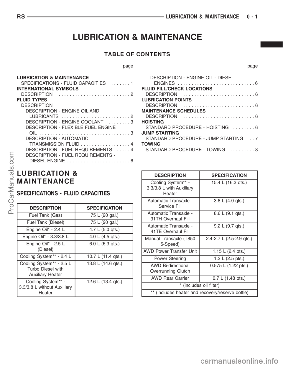
SPECIFICATIONS - FLUID CAPACITIES.......1
INTERNATIONAL SYMBOLS
DESCRIPTION..........................2
FLUID TYPES
DESCRIPTION
DESCRIPTION - ENGINE OIL AND
LUBRICANTS.........................2
DESCRIPTION - ENGINE COOLANT........3
DESCRIPTION - FLEXIBLE FUEL ENGINE
OIL .................................3
DESCRIPTION - AUTOMATIC
TRANSMISSION FLUID..................4
DESCRIPTION - FUEL REQUIREMENTS.....4
DESCRIPTION - FUEL REQUIREMENTS -
DIESEL ENGINE.......................6DESCRIPTION - ENGINE OIL - DIESEL
ENGINES............................6
FLUID FILL/CHECK LOCATIONS
DESCRIPTION..........................6
LUBRICATION POINTS
DESCRIPTION..........................6
MAINTENANCE SCHEDULES
DESCRIPTION..........................6
HOISTING
STANDARD PROCEDURE - HOISTING........6
JUMP STARTING
STANDARD PROCEDURE - JUMP STARTING . . 7
TOWING
STANDARD PROCEDURE - TOWING.........8
LUBRICATION &
MAINTENANCE
SPECIFICATIONS - FLUID CAPACITIES
DESCRIPTION SPECIFICATION
Fuel Tank (Gas) 75 L (20 gal.)
Fuel Tank (Diesel) 75 L (20 gal.)
Engine Oil* - 2.4 L 4.7 L (5.0 qts.)
Engine Oil* - 3.3/3.8 L 4.0 L (4.5 qts.)
Engine Oil* - 2.5 L
(Diesel)6.0 L (6.3 qts.)
Cooling System** - 2.4 L 10.7 L (11.4 qts.)
Cooling System** - 2.5 L
Turbo Diesel with
Auxiliary Heater13.8 L (14.6 qts.)
Cooling System** -
3.3/3.8 L without Auxiliary
Heater12.6 L (13.4 qts.)
DESCRIPTION SPECIFICATION
Cooling System** -
3.3/3.8 L with Auxiliary
Heater15.4 L (16.3 qts.)
Automatic Transaxle -
Service Fill3.8 L (4.0 qts.)
Automatic Transaxle -
31TH Overhaul Fill8.6 L (9.1 qts.)
Automatic Transaxle -
41TE Overhaul Fill9.2 L (9.7 qts.)
Manual Transaxle (T850
5-Speed)2.4-2.7 L (2.5-2.9 qts.)
AWD Power Transfer Unit 1.15 L (2.4 pts.)
Power Steering 1.2 L (2.5 pts.)
AWD Bi-directional
Overrunning Clutch0.575 L (1.22 pts.)
AWD Rear Carrier 0.7 L (1.48 pts.)
* (includes oil filter)
** (includes heater and recovery/reserve bottle)
RSLUBRICATION & MAINTENANCE0-1
ProCarManuals.com
Page 17 of 2399
WARNING: Ethanol vapors are extremely flammable
and could cause serious personal injury. Never
have any smoking materials lit in or near the vehi-
cle when removing the fuel filler tube cap (gas cap)
or filling the tank. Do not use E-85 as a cleaning
agent and never use it near an open flame.
FUEL REQUIREMENTS
The vehicle will operate on both unleaded gasoline
with an octane rating of 87, or E-85 fuel, or any mix-
ture of these two.
For best results, a refueling pattern that alternates
between E-85 and unleaded gasoline should be
avoided. When you do switch fuels, it is recom-
mended that
²you do not switch when the fuel gauge indicates
less than 1/4 full
²you do not add less than 5 gallons when refuel-
ing
²you operate the vehicle immediately after refuel-
ing for a period of at least 5 minutes
Observing these precautions will avoid possible
hard starting and/or significant deterioration in
driveability during warm up.
FFV STARTING
The characteristics of E-85 fuel make it unsuitable
for use when ambient temperatures fall below 0ÉF. In
the range of 0ÉF to 32ÉF, you may experience an
increase in the time it takes for your engine to start,
and a deterioration in driveability (sags and/or hesi-
tations) until the engine is fully warmed up.
Engine Operating on E-85 Fuel
If vehicle operates on E-85 fuel either full or part-
time, use only MopartFlexible Fuel 5W-30 engine oil
or an equivalent that meets DaimlerChrysler Stan-
dard MS-9214. Equivalent commercial Flexible Fuel
engine oils may be labeled as Multi-Fuel, Variable
Fuel, Flexible Fuel, etc. These engine oils may be
satisfactory if they meet the DaimlerChrysler Stan-
dard.
SAE 5W-30 engine oil is preferred for use in Flex-
ible Fuel engines.
CAUTION: If Flexible Fuel engine oil is not used
when using E-85 fuel, engine wear or damage may
result.
CRUISING RANGE
Because E-85 fuel contains less energy per gallon
than gasoline, you will experience an increase in fuel
consumption. You can expect your MPG and your
driving range to decrease by about 30% compared to
gasoline operation.
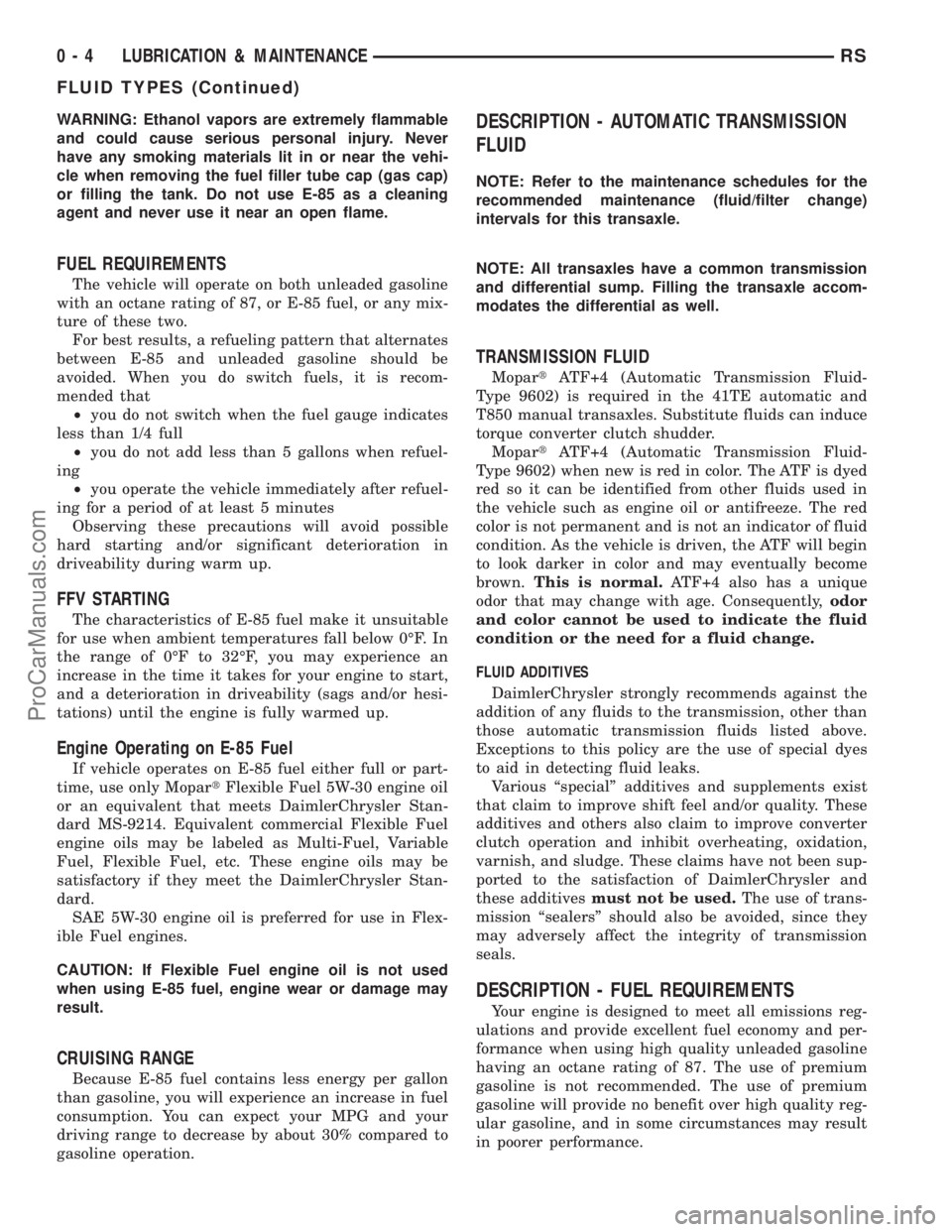
DESCRIPTION - AUTOMATIC TRANSMISSION
FLUID
NOTE: Refer to the maintenance schedules for the
recommended maintenance (fluid/filter change)
intervals for this transaxle.
NOTE: All transaxles have a common transmission
and differential sump. Filling the transaxle accom-
modates the differential as well.
TRANSMISSION FLUID
MopartATF+4 (Automatic Transmission Fluid-
Type 9602) is required in the 41TE automatic and
T850 manual transaxles. Substitute fluids can induce
torque converter clutch shudder.
MopartATF+4 (Automatic Transmission Fluid-
Type 9602) when new is red in color. The ATF is dyed
red so it can be identified from other fluids used in
the vehicle such as engine oil or antifreeze. The red
color is not permanent and is not an indicator of fluid
condition. As the vehicle is driven, the ATF will begin
to look darker in color and may eventually become
brown.This is normal.ATF+4 also has a unique
odor that may change with age. Consequently,odor
and color cannot be used to indicate the fluid
condition or the need for a fluid change.
FLUID ADDITIVES
DaimlerChrysler strongly recommends against the
addition of any fluids to the transmission, other than
those automatic transmission fluids listed above.
Exceptions to this policy are the use of special dyes
to aid in detecting fluid leaks.
Various ªspecialº additives and supplements exist
that claim to improve shift feel and/or quality. These
additives and others also claim to improve converter
clutch operation and inhibit overheating, oxidation,
varnish, and sludge. These claims have not been sup-
ported to the satisfaction of DaimlerChrysler and
these additivesmust not be used.The use of trans-
mission ªsealersº should also be avoided, since they
may adversely affect the integrity of transmission
seals.
DESCRIPTION - FUEL REQUIREMENTS
Your engine is designed to meet all emissions reg-
ulations and provide excellent fuel economy and per-
formance when using high quality unleaded gasoline
having an octane rating of 87. The use of premium
gasoline is not recommended. The use of premium
gasoline will provide no benefit over high quality reg-
ular gasoline, and in some circumstances may result
in poorer performance.
0 - 4 LUBRICATION & MAINTENANCERS
FLUID TYPES (Continued)
ProCarManuals.com
Page 84 of 2399
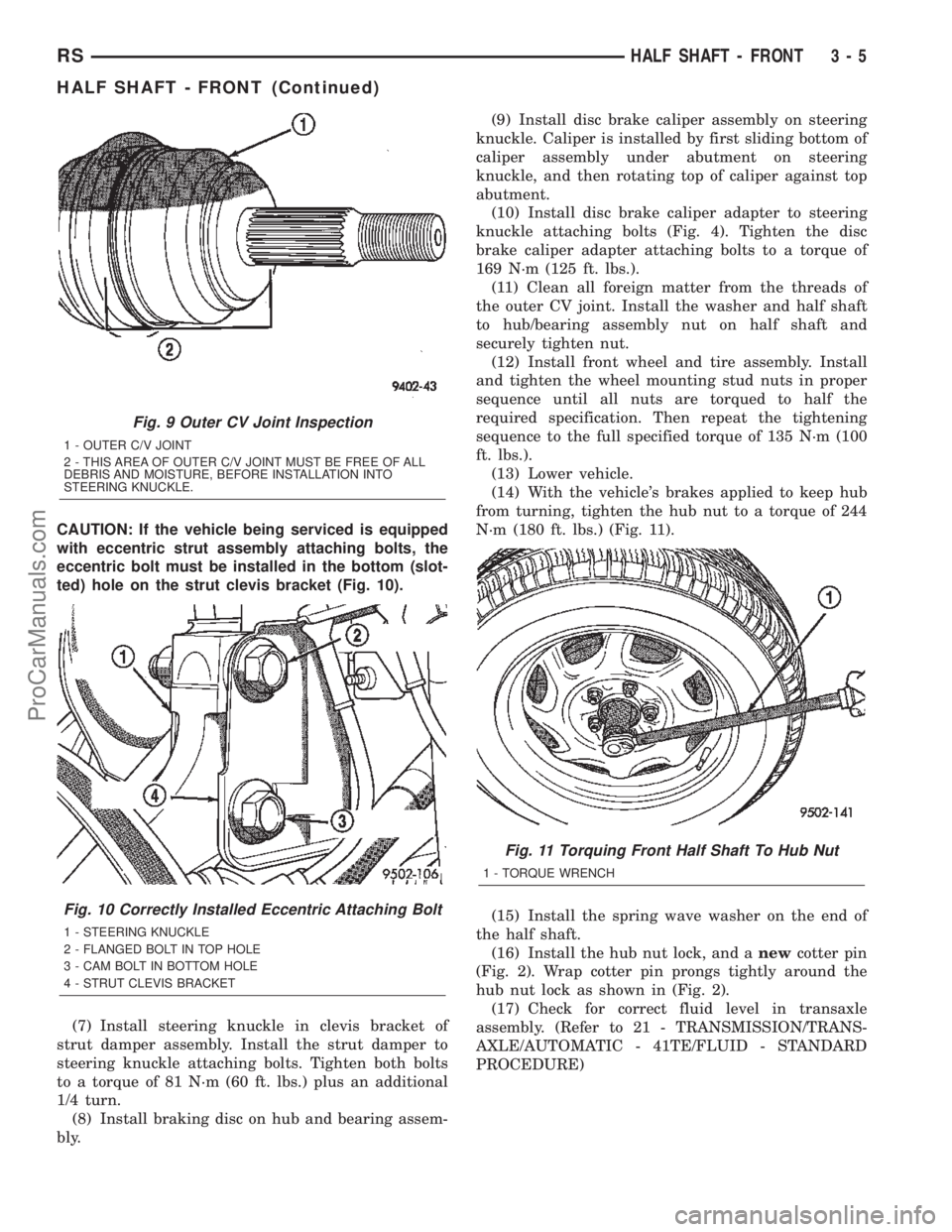
CAUTION: If the vehicle being serviced is equipped
with eccentric strut assembly attaching bolts, the
eccentric bolt must be installed in the bottom (slot-
ted) hole on the strut clevis bracket (Fig. 10).
(7) Install steering knuckle in clevis bracket of
strut damper assembly. Install the strut damper to
steering knuckle attaching bolts. Tighten both bolts
to a torque of 81 N´m (60 ft. lbs.) plus an additional
1/4 turn.
(8) Install braking disc on hub and bearing assem-
bly.(9) Install disc brake caliper assembly on steering
knuckle. Caliper is installed by first sliding bottom of
caliper assembly under abutment on steering
knuckle, and then rotating top of caliper against top
abutment.
(10) Install disc brake caliper adapter to steering
knuckle attaching bolts (Fig. 4). Tighten the disc
brake caliper adapter attaching bolts to a torque of
169 N´m (125 ft. lbs.).
(11) Clean all foreign matter from the threads of
the outer CV joint. Install the washer and half shaft
to hub/bearing assembly nut on half shaft and
securely tighten nut.
(12) Install front wheel and tire assembly. Install
and tighten the wheel mounting stud nuts in proper
sequence until all nuts are torqued to half the
required specification. Then repeat the tightening
sequence to the full specified torque of 135 N´m (100
ft. lbs.).
(13) Lower vehicle.
(14) With the vehicle's brakes applied to keep hub
from turning, tighten the hub nut to a torque of 244
N´m (180 ft. lbs.) (Fig. 11).
(15) Install the spring wave washer on the end of
the half shaft.
(16) Install the hub nut lock, and anewcotter pin
(Fig. 2). Wrap cotter pin prongs tightly around the
hub nut lock as shown in (Fig. 2).
(17) Check for correct fluid level in transaxle
assembly. (Refer to 21 - TRANSMISSION/TRANS-
AXLE/AUTOMATIC - 41TE/FLUID - STANDARD
PROCEDURE)
Fig. 9 Outer CV Joint Inspection
1 - OUTER C/V JOINT
2 - THIS AREA OF OUTER C/V JOINT MUST BE FREE OF ALL
DEBRIS AND MOISTURE, BEFORE INSTALLATION INTO
STEERING KNUCKLE.
Fig. 10 Correctly Installed Eccentric Attaching Bolt
1 - STEERING KNUCKLE
2 - FLANGED BOLT IN TOP HOLE
3 - CAM BOLT IN BOTTOM HOLE
4 - STRUT CLEVIS BRACKET
Fig. 11 Torquing Front Half Shaft To Hub Nut
1 - TORQUE WRENCH
RSHALF SHAFT - FRONT3-5
HALF SHAFT - FRONT (Continued)
ProCarManuals.com
Page 103 of 2399
REAR DRIVELINE MODULE
TABLE OF CONTENTS
page page
REAR DRIVELINE MODULE
DESCRIPTION.........................24
OPERATION...........................24
DIAGNOSIS AND TESTING
DIAGNOSIS AND TESTING - REAR
DRIVELINE MODULE NOISE.............25
DIAGNOSIS AND TESTING - REAR
DRIVELINE MODULE OPERATION........27
REMOVAL.............................27
DISASSEMBLY.........................28
ASSEMBLY............................30
INSTALLATION.........................34
SPECIFICATIONS - REAR DRIVELINE
MODULE............................35
SPECIAL TOOLS.......................35
BI-DIRECTIONAL OVERRUNNING CLUTCH
DESCRIPTION.........................36
OPERATION...........................38
DIFFERENTIAL ASSEMBLY
DESCRIPTION.........................41OPERATION...........................41
FLUID - DIFFERENTIAL ASSEMBLY
STANDARD PROCEDURE - DIFFERENTIAL
ASSEMBLY FLUID DRAIN AND FILL.......42
FLUID
STANDARD PROCEDURE - OVERRUNNING
CLUTCH HOUSING FLUID CHANGE.......43
VISCOUS COUPLER
DESCRIPTION.........................44
OPERATION...........................44
TORQUE ARM
REMOVAL.............................46
INSTALLATION.........................46
INPUT FLANGE SEAL
REMOVAL.............................46
INSTALLATION.........................47
OUTPUT FLANGE SEAL
REMOVAL.............................48
INSTALLATION.........................49
REAR DRIVELINE MODULE
DESCRIPTION
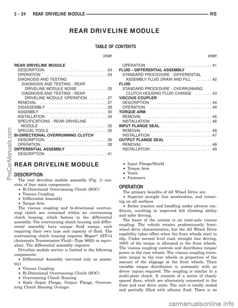
The rear driveline module assembly (Fig. 1) con-
sists of four main components:
²Bi-Directional Overrunning Clutch (BOC)
²Viscous Coupling
²Differential Assembly
²Torque Arm
The viscous coupling and bi-directional overrun-
ning clutch are contained within an overrunning
clutch housing, which fastens to the differential
assembly. The overrunning clutch housing and differ-
ential assembly have unique fluid sumps, each
requiring their own type and capacity of fluid. The
overrunning clutch housing requires MopartATF+4
(Automatic Transmission FluidÐType 9602) or equiv-
alent. The differential assembly requires
Driveline module service is limited to the following
components:
²Differential Assembly (serviced only as assem-
bly)
²Viscous Coupling
²Bi-Directional Overrunning Clutch (BOC)
²Overrunning Clutch Housing
²Seals (Input Flange, Output Flange, Overrun-
ning Clutch Housing O-rings)²Input Flange/Shield
²Torque Arm
²Vents
²Fasteners
OPERATION
The primary benefits of All Wheel Drive are:
²Superior straight line acceleration, and corner-
ing on all surfaces
²Better traction and handling under adverse con-
ditions, resulting in improved hill climbing ability
and safer driving.
The heart of the system is an inter-axle viscous
coupling. The vehicle retains predominantly front-
wheel drive characteristics, but the All Wheel Drive
capability takes effect when the front wheels start to
slip. Under normal level road, straight line driving,
100% of the torque is allocated to the front wheels.
The viscous coupling controls and distributes torque/
power to the rear wheels. The viscous coupling trans-
mits torque to the rear wheels in proportion of the
amount of the slippage at the front wheels. Thais
variable torque distribution is automatic with no
driver inputs required. The coupling is similar to a
multi-plate clutch. It consists of a series of closely
spaced discs, which are alternately connected to the
front and rear drive units. The unit is totally sealed
and partially filled with silicone fluid. There is no
3 - 24 REAR DRIVELINE MODULERS
ProCarManuals.com
Page 104 of 2399
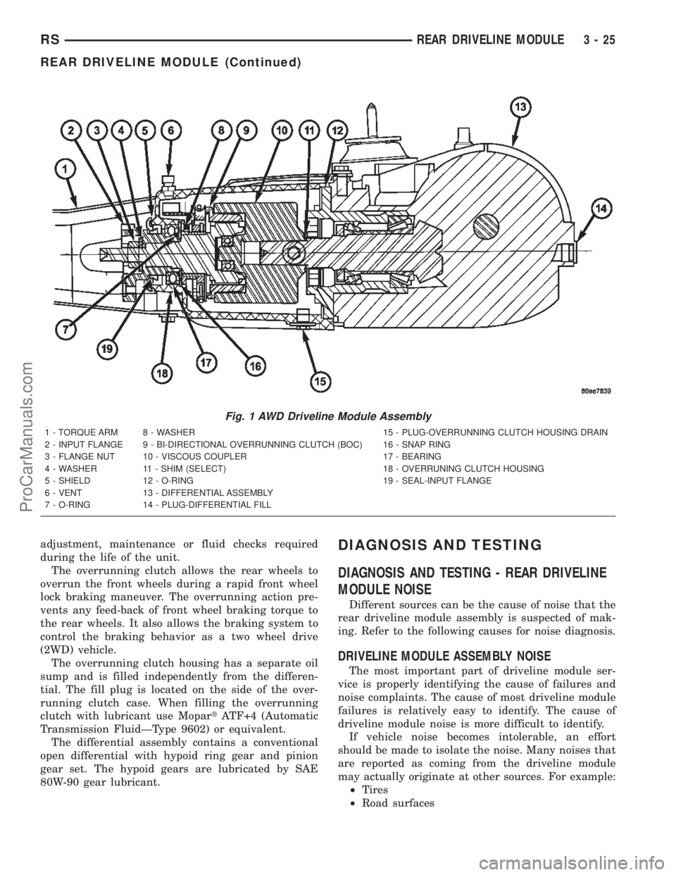
adjustment, maintenance or fluid checks required
during the life of the unit.
The overrunning clutch allows the rear wheels to
overrun the front wheels during a rapid front wheel
lock braking maneuver. The overrunning action pre-
vents any feed-back of front wheel braking torque to
the rear wheels. It also allows the braking system to
control the braking behavior as a two wheel drive
(2WD) vehicle.
The overrunning clutch housing has a separate oil
sump and is filled independently from the differen-
tial. The fill plug is located on the side of the over-
running clutch case. When filling the overrunning
clutch with lubricant use MopartATF+4 (Automatic
Transmission FluidÐType 9602) or equivalent.
The differential assembly contains a conventional
open differential with hypoid ring gear and pinion
gear set. The hypoid gears are lubricated by SAE
80W-90 gear lubricant.DIAGNOSIS AND TESTING
DIAGNOSIS AND TESTING - REAR DRIVELINE
MODULE NOISE
Different sources can be the cause of noise that the
rear driveline module assembly is suspected of mak-
ing. Refer to the following causes for noise diagnosis.
DRIVELINE MODULE ASSEMBLY NOISE
The most important part of driveline module ser-
vice is properly identifying the cause of failures and
noise complaints. The cause of most driveline module
failures is relatively easy to identify. The cause of
driveline module noise is more difficult to identify.
If vehicle noise becomes intolerable, an effort
should be made to isolate the noise. Many noises that
are reported as coming from the driveline module
may actually originate at other sources. For example:
²Tires
²Road surfaces
Fig. 1 AWD Driveline Module Assembly
1 - TORQUE ARM 8 - WASHER 15 - PLUG-OVERRUNNING CLUTCH HOUSING DRAIN
2 - INPUT FLANGE 9 - BI-DIRECTIONAL OVERRUNNING CLUTCH (BOC) 16 - SNAP RING
3 - FLANGE NUT 10 - VISCOUS COUPLER 17 - BEARING
4 - WASHER 11 - SHIM (SELECT) 18 - OVERRUNING CLUTCH HOUSING
5 - SHIELD 12 - O-RING 19 - SEAL-INPUT FLANGE
6 - VENT 13 - DIFFERENTIAL ASSEMBLY
7 - O-RING 14 - PLUG-DIFFERENTIAL FILL
RSREAR DRIVELINE MODULE3-25
REAR DRIVELINE MODULE (Continued)
ProCarManuals.com
Page 122 of 2399
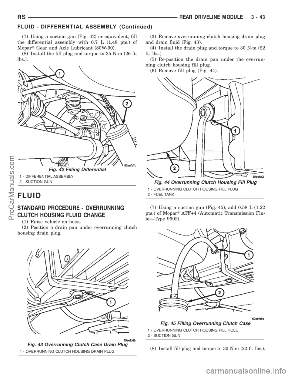
(7) Using a suction gun (Fig. 42) or equivalent, fill
the differential assembly with 0.7 L (1.48 pts.) of
MopartGear and Axle Lubricant (80W-90).
(8) Install the fill plug and torque to 35 N´m (26 ft.
lbs.).
FLUID
STANDARD PROCEDURE - OVERRUNNING
CLUTCH HOUSING FLUID CHANGE
(1) Raise vehicle on hoist.
(2) Position a drain pan under overrunning clutch
housing drain plug.(3) Remove overrunning clutch housing drain plug
and drain fluid (Fig. 43).
(4) Install the drain plug and torque to 30 N´m (22
ft. lbs.).
(5) Re-position the drain pan under the overrun-
ning clutch housing fill plug.
(6) Remove fill plug (Fig. 44).
(7) Using a suction gun (Fig. 45), add 0.58 L (1.22
pts.) of MopartATF+4 (Automatic Transmission Flu-
idÐType 9602).
(8)
Install fill plug and torque to 30 N´m (22 ft. lbs.).Fig. 43 Overrunning Clutch Case Drain Plug
1 - OVERRUNNING CLUTCH HOUSING DRAIN PLUG
Fig. 42 Filling Differential
1 - DIFFERENTIAL ASSEMBLY
2 - SUCTION GUN
Fig. 44 Overrunning Clutch Housing Fill Plug
1 - OVERRUNNING CLUTCH HOUSING FILL PLUG
2 - FUEL TANK
Fig. 45 Filling Overrunning Clutch Case
1 - OVERRUNNING CLUTCH HOUSING FILL HOLE
2 - SUCTION GUN
RSREAR DRIVELINE MODULE3-43
FLUID - DIFFERENTIAL ASSEMBLY (Continued)
ProCarManuals.com
Page 287 of 2399
TRANSMISSION
TABLE OF CONTENTS
page page
TRANSMISSION
STANDARD PROCEDURE - FLUSHING
COOLERS AND TUBES.................38
TRANSMISSION OIL COOLER
DESCRIPTION.........................38
REMOVAL.............................38CLEANING............................39
INSPECTION..........................39
INSTALLATION.........................39
TRANSMISSION OIL COOLER LINES
REMOVAL.............................39
INSTALLATION.........................40
TRANSMISSION
STANDARD PROCEDURE - FLUSHING
COOLERS AND TUBES
The recommended procedure for cooler flushing is
to use Tool 6906 Cooler Flusher.
WARNING: WEAR PROTECTIVE EYEWEAR THAT
MEETS THE REQUIREMENTS OF OSHA AND ANSI
Z87.1±1968. WEAR STANDARD INDUSTRIAL RUB-
BER GLOVES. KEEP LIT CIGARETTES, SPARKS,
FLAMES, AND OTHER IGNITION SOURCES AWAY
FROM THE AREA TO PREVENT THE IGNITION OF
COMBUSTIBLE LIQUIDS AND GASES. KEEP A
CLASS (B) FIRE EXTINGUISHER IN THE AREA
WHERE THE FLUSHER WILL BE USED.
WARNING: KEEP THE AREA WELL VENTILATED.
DO NOT LET FLUSHING SOLVENT COME IN CON-
TACT WITH YOUR EYES OR SKIN: IF EYE CONTAM-
INATION OCCURS, FLUSH EYES WITH WATER FOR
15 TO 20 SECONDS. REMOVE CONTAMINATED
CLOTHING AND WASH AFFECTED SKIN WITH
SOAP AND WATER. SEEK MEDICAL ATTENTION.
(1) Remove cover plate filler plug on Tool 6906.
Fill reservoir 1/2 to 3/4 full of fresh flushing solution.
Use MopartTransmission Cooler Flush (MS-552) or
equivalent solution conforming to MS-552. Flushing
solvents are petroleum based solutions generally
used to clean automatic transmission components.
DO NOTuse solvents containing acids, water, gaso-
line, or any other corrosive liquids.
(2) Reinstall filler plug on Tool 6906.
(3) Verify pump power switch is turned OFF. Con-
nect red alligator clip to positive (+) battery post.
Connect black (-) alligator clip to a good ground.
NOTE: When flushing transmission cooler and
lines, ALWAYS reverse flush.(4) Connect the BLUE pressure line to the OUT-
LET (From) cooler line.
(5) Connect the CLEAR return line to the INLET
(To) cooler line
(6) Turn pump ON for two to three minutes to
flush cooler and lines.
(7) Turn pump OFF.
(8) Disconnect CLEAR suction line from reservoir
at cover plate. Disconnect CLEAR return line at
cover plate, and place it in a drain pan.
(9) Turn pump ON for 30 seconds to purge flush-
ing solution from cooler and lines. Turn pump OFF.
(10) Place CLEAR suction line into a one quart
container of MopartATF+4 (Automatic Transmission
FluidÐType 9602).
(11) Turn pump ON until all transmission fluid is
removed from the one quart container and lines. This
purges any residual cleaning solvent from the trans-
mission cooler and lines. Turn pump OFF.
(12) Disconnect alligator clips from battery. Recon-
nect flusher lines to cover plate, and remove flushing
adapters from cooler lines.
TRANSMISSION OIL COOLER
DESCRIPTION
The transmission oil cooler is an oil-to-air type
cooler that is mounted between the front of the radi-
ator and back side of the A/C condenser (Fig. 2). Use
only approved transmission oil cooler hoses that are
molded to fit the space available.
REMOVAL
(1) Remove the radiator. (Refer to 7 - COOLING/
ENGINE/RADIATOR - REMOVAL)
(2) Disconnect lines from oil cooler (Fig. 1).
(3) Remove oil cooler attaching screws (Fig. 2).
(4) Remove the oil cooler.
7 - 38 TRANSMISSIONRS
ProCarManuals.com
Page 746 of 2399
8W-15 GROUND DISTRIBUTION
Component PageA/C Compressor Clutch...................8W-15-7, 8
A/C- Heater Control....................8W-15-9, 11
Adjustable Pedals Module..................8W-15-17
Airbag Control Module....................8W-15-12
Auto Temp Control.......................8W-15-9
Automatic Day/Night Mirror.................8W-15-21
Autostick Switch........................8W-15-10
Back-Up Lamp Switch....................8W-15-3, 7
Battery.............................8W-15-2, 3
Body Control Module.....................8W-15-22
Brake Fluid Level Switch...................8W-15-17
Brake Lamp Switch......................8W-15-17
Cabin Heater Assist.......................8W-15-8
Center Dome Lamp......................8W-15-21
Center High Mounted Stop Lamp..............8W-15-26
Clutch Pedal Upstop Switch.................8W-15-18
Controller Antilock Brake..................8W-15-2, 3
Crank Case Ventilation Heater................8W-15-8
Crankshaft Position Sensor..................8W-15-3
Data Link Connector..................8W-15-2, 3, 17
Dosing Pump...........................8W-15-8
Driver Door Courtesy Lamp...............8W-15-15, 20
Driver Door Lock Switch.................8W-15-15, 20
Driver Heated Seat Cushion.................8W-15-11
Driver Heated Seat Module.................8W-15-11
Driver Power Seat Switch..................8W-15-11
Driver Power Window Switch..............8W-15-15, 20
Engine Control Module.....................8W-15-3
Floor Console Lamp......................8W-15-25
Floor Console Power Outlet.................8W-15-25
Front Blower Module.....................8W-15-11
Front Cigar Lighter.......................8W-15-9
Front Control Module..................8W-15-7, 8, 18
Front Reading Lamps/Switch................8W-15-21
Fuel Heater...........................8W-15-25
Fuel Heater Relay........................8W-15-3
Fuel Pump Module.......................8W-15-25
G100..............................8W-15-2, 3
G101..............................8W-15-2, 3
G102.............................8W-15-4, 5, 6
G103..............................8W-15-7, 8
G200...........................8W-15-9, 10, 11
G201...............................8W-15-12
G202...............................8W-15-13
G300........................8W-15-14, 16, 17, 18
G301........................8W-15-19, 20, 21, 22
G302...........................8W-15-23, 24, 25
G400.............................8W-15-25, 26
Glove Box Lamp........................8W-15-10
Halo Lamp............................8W-15-10
Headlamp Switch........................8W-15-9
Headlamp Washer Pump Motor................8W-15-6
High Note Horn........................8W-15-5, 6
Hood Ajar Switch........................8W-15-18
Instrument Cluster.......................8W-15-9
Instrument Panel Switch Bank...............8W-15-10
Integrated Power Module............8W-15-2, 3, 7, 8, 18
Left B-Pillar Switch......................8W-15-17
Left Cinch/Release Motor...................8W-15-14
Left Combination Relay....................8W-15-24
Left Cylinder Lock Switch................8W-15-15, 16
Left Door Speaker.......................8W-15-13
Left Fog Lamp........................8W-15-5, 6
Left Front Door Ajar Switch.................8W-15-16
Left Front Door Lock Motor/Ajar Switch.......8W-15-15, 16
Left Front Park/Turn Signal Lamp..............8W-15-5
Left Full Open Switch.....................8W-15-14
Left Headlamp.........................8W-15-18
Left Headlamp Leveling Motor................8W-15-6
Left High Beam Lamp....................8W-15-18
Left Liftgate Flood Lamp...................8W-15-26
Left Low Beam Lamp.....................8W-15-18
Left Mid Reading Lamp....................8W-15-21
Left Park Lamp.........................8W-15-18
Left Power Mirror.......................8W-15-10
Left Rear Lamp Assembly..................8W-15-24
Left Rear Reading Lamp...................8W-15-21
Left Side Impact Airbag Control Module.........8W-15-12
Left Sliding Door Control Module..............8W-15-14
Left Sliding Door Latch Sensing Switch..........8W-15-14
Left Sliding Door Lock Motor................8W-15-14Component PageLeft Sliding Door Lock Motor/Ajar Switch.........8W-15-14
Left Sliding Door Motor....................8W-15-14
Left Stop/Turn Signal Relay.................8W-15-24
Left Turn Signal Lamp....................8W-15-18
Left Visor/Vanity Lamp....................8W-15-21
License Lamp........................8W-15-23, 26
Lift Pump Motor........................8W-15-25
Liftgate Ajar Switch......................8W-15-26
Liftgate Cinch/Release Motor................8W-15-23
Liftgate Cylinder Lock Switch................8W-15-26
Liftgate Right Pinch Sensor.................8W-15-23
Low Note Horn........................8W-15-5, 6
Memory Seat/Mirror Module.................8W-15-11
Overhead Console.......................8W-15-21
Oxygen Sensor 1/2 Downstream...............8W-15-7
Park/Neutral Position Switch.................8W-15-7
Passenger Door Courtesy Lamp............8W-15-16, 20
Passenger Door Lock Switch..............8W-15-16, 20
Passenger Heated Seat Module...............8W-15-22
Passenger Power Seat Switch................8W-15-22
Passenger Power Window Switch............8W-15-16, 20
Power Folding Mirror Switch................8W-15-11
Power Liftgate Module....................8W-15-23
Power Liftgate Motor.....................8W-15-23
Power Mirror Switch......................8W-15-11
Power Outlet...........................8W-15-9
Power Window Switch.....................8W-15-15
Powertrain Control Module..................8W-15-2
Radiator Fan No. 1.......................8W-15-4
Radiator Fan No. 2.......................8W-15-4
Radiator Fan Relay.......................8W-15-4
Radiator Fan Relay No. 3...................8W-15-4
Radio...............................8W-15-13
Rear Auto Temp Control Switch...............8W-15-17
Rear Blower Front Control Switch.............8W-15-11
Rear Blower Motor Power Module...........8W-15-11, 25
Rear Blower Rear Control Switch..............8W-15-17
Rear Dome Lamp........................8W-15-21
Rear Power Outlet.......................8W-15-25
Rear Window Defogger Grid.................8W-15-26
Rear Wiper Motor.......................8W-15-26
Remote Keyless Entry Module................8W-15-10
Right B-Pillar Switch.....................8W-15-22
Right Cinch/Release Motor..................8W-15-19
Right Combination Relay...................8W-15-24
Right Cylinder Lock Switch.................8W-15-20
Right Door Speaker......................8W-15-13
Right Fog Lamp........................8W-15-5, 6
Right Front Door Ajar Switch................8W-15-20
Right Front Door Lock Motor/Ajar Switch.........8W-15-20
Right Front Park/Turn Signal Lamp.............8W-15-5
Right Full Open Switch....................8W-15-19
Right Headlamp........................8W-15-18
Right Headlamp Leveling Motor...............8W-15-6
Right High Beam Lamp....................8W-15-18
Right Liftgate Flood Lamp..................8W-15-26
Right Low Beam Lamp....................8W-15-18
Right Mid Reading Lamp...................8W-15-21
Right Park Lamp........................8W-15-18
Right Power Mirror......................8W-15-10
Right Rear Lamp Assembly.................8W-15-25
Right Rear Reading Lamp..................8W-15-21
Right Side Impact Airbag Control Module.........8W-15-12
Right Sliding Door Control Module.............8W-15-19
Right Sliding Door Latch Sensing Switch.........8W-15-19
Right Sliding Door Lock Motor...............8W-15-19
Right Sliding Door Lock Motor/Ajar Switch........8W-15-19
Right Sliding Door Motor...................8W-15-19
Right Stop/Turn Signal Relay................8W-15-24
Right Turn Signal Lamp...................8W-15-18
Right Visor/Vanity Lamp...................8W-15-21
Sentry Key Immobilizer Module...............8W-15-10
Speed Control Servo.......................8W-15-7
Traction Control Switch....................8W-15-10
Trailer Tow Connector.....................8W-15-24
Transmission Control Module.................8W-15-2
Transmission Control Relay..................8W-15-2
Transmission Range Sensor..................8W-15-7
Washer Fluid Level Switch.................8W-15-5, 6
Wiper Module..........................8W-15-17
RS8W-15 GROUND DISTRIBUTION8W-15-1
ProCarManuals.com
Page 1032 of 2399
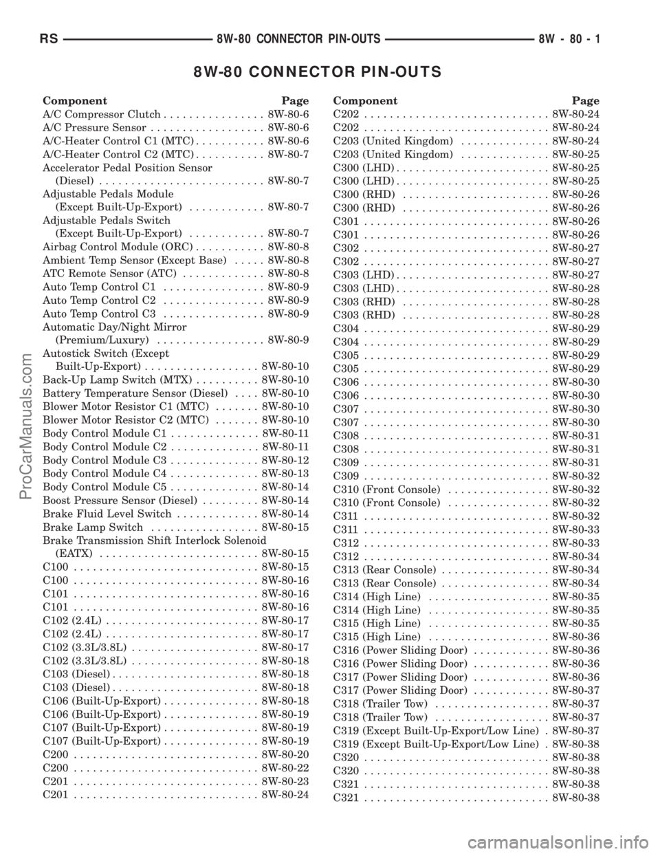
8W-80 CONNECTOR PIN-OUTS
Component Page
A/C Compressor Clutch................ 8W-80-6
A/C Pressure Sensor.................. 8W-80-6
A/C-Heater Control C1 (MTC)........... 8W-80-6
A/C-Heater Control C2 (MTC)........... 8W-80-7
Accelerator Pedal Position Sensor
(Diesel).......................... 8W-80-7
Adjustable Pedals Module
(Except Built-Up-Export)............ 8W-80-7
Adjustable Pedals Switch
(Except Built-Up-Export)............ 8W-80-7
Airbag Control Module (ORC)........... 8W-80-8
Ambient Temp Sensor (Except Base)..... 8W-80-8
ATC Remote Sensor (ATC)............. 8W-80-8
Auto Temp Control C1................ 8W-80-9
Auto Temp Control C2................ 8W-80-9
Auto Temp Control C3................ 8W-80-9
Automatic Day/Night Mirror
(Premium/Luxury)................. 8W-80-9
Autostick Switch (Except
Built-Up-Export).................. 8W-80-10
Back-Up Lamp Switch (MTX).......... 8W-80-10
Battery Temperature Sensor (Diesel).... 8W-80-10
Blower Motor Resistor C1 (MTC)....... 8W-80-10
Blower Motor Resistor C2 (MTC)....... 8W-80-10
Body Control Module C1.............. 8W-80-11
Body Control Module C2.............. 8W-80-11
Body Control Module C3.............. 8W-80-12
Body Control Module C4.............. 8W-80-13
Body Control Module C5.............. 8W-80-14
Boost Pressure Sensor (Diesel)......... 8W-80-14
Brake Fluid Level Switch............. 8W-80-14
Brake Lamp Switch................. 8W-80-15
Brake Transmission Shift Interlock Solenoid
(EATX) ......................... 8W-80-15
C100............................. 8W-80-15
C100............................. 8W-80-16
C101............................. 8W-80-16
C101............................. 8W-80-16
C102 (2.4L)........................ 8W-80-17
C102 (2.4L)........................ 8W-80-17
C102 (3.3L/3.8L).................... 8W-80-17
C102 (3.3L/3.8L).................... 8W-80-18
C103 (Diesel)....................... 8W-80-18
C103 (Diesel)....................... 8W-80-18
C106 (Built-Up-Export)............... 8W-80-18
C106 (Built-Up-Export)............... 8W-80-19
C107 (Built-Up-Export)............... 8W-80-19
C107 (Built-Up-Export)............... 8W-80-19
C200............................. 8W-80-20
C200............................. 8W-80-22
C201............................. 8W-80-23
C201............................. 8W-80-24Component Page
C202............................. 8W-80-24
C202............................. 8W-80-24
C203 (United Kingdom).............. 8W-80-24
C203 (United Kingdom).............. 8W-80-25
C300 (LHD)........................ 8W-80-25
C300 (LHD)........................ 8W-80-25
C300 (RHD)....................... 8W-80-26
C300 (RHD)....................... 8W-80-26
C301............................. 8W-80-26
C301............................. 8W-80-26
C302............................. 8W-80-27
C302............................. 8W-80-27
C303 (LHD)........................ 8W-80-27
C303 (LHD)........................ 8W-80-28
C303 (RHD)....................... 8W-80-28
C303 (RHD)....................... 8W-80-28
C304............................. 8W-80-29
C304............................. 8W-80-29
C305............................. 8W-80-29
C305............................. 8W-80-29
C306............................. 8W-80-30
C306............................. 8W-80-30
C307............................. 8W-80-30
C307............................. 8W-80-30
C308............................. 8W-80-31
C308............................. 8W-80-31
C309............................. 8W-80-31
C309............................. 8W-80-32
C310 (Front Console)................ 8W-80-32
C310 (Front Console)................ 8W-80-32
C311 ............................. 8W-80-32
C311 ............................. 8W-80-33
C312............................. 8W-80-33
C312............................. 8W-80-34
C313 (Rear Console)................. 8W-80-34
C313 (Rear Console)................. 8W-80-34
C314 (High Line)................... 8W-80-35
C314 (High Line)................... 8W-80-35
C315 (High Line)................... 8W-80-35
C315 (High Line)................... 8W-80-36
C316 (Power Sliding Door)............ 8W-80-36
C316 (Power Sliding Door)............ 8W-80-36
C317 (Power Sliding Door)............ 8W-80-36
C317 (Power Sliding Door)............ 8W-80-37
C318 (Trailer Tow).................. 8W-80-37
C318 (Trailer Tow).................. 8W-80-37
C319 (Except Built-Up-Export/Low Line) . 8W-80-37
C319 (Except Built-Up-Export/Low Line) . 8W-80-38
C320............................. 8W-80-38
C320............................. 8W-80-38
C321............................. 8W-80-38
C321............................. 8W-80-38
RS8W-80 CONNECTOR PIN-OUTS8W-80-1
ProCarManuals.com
Page 1101 of 2399
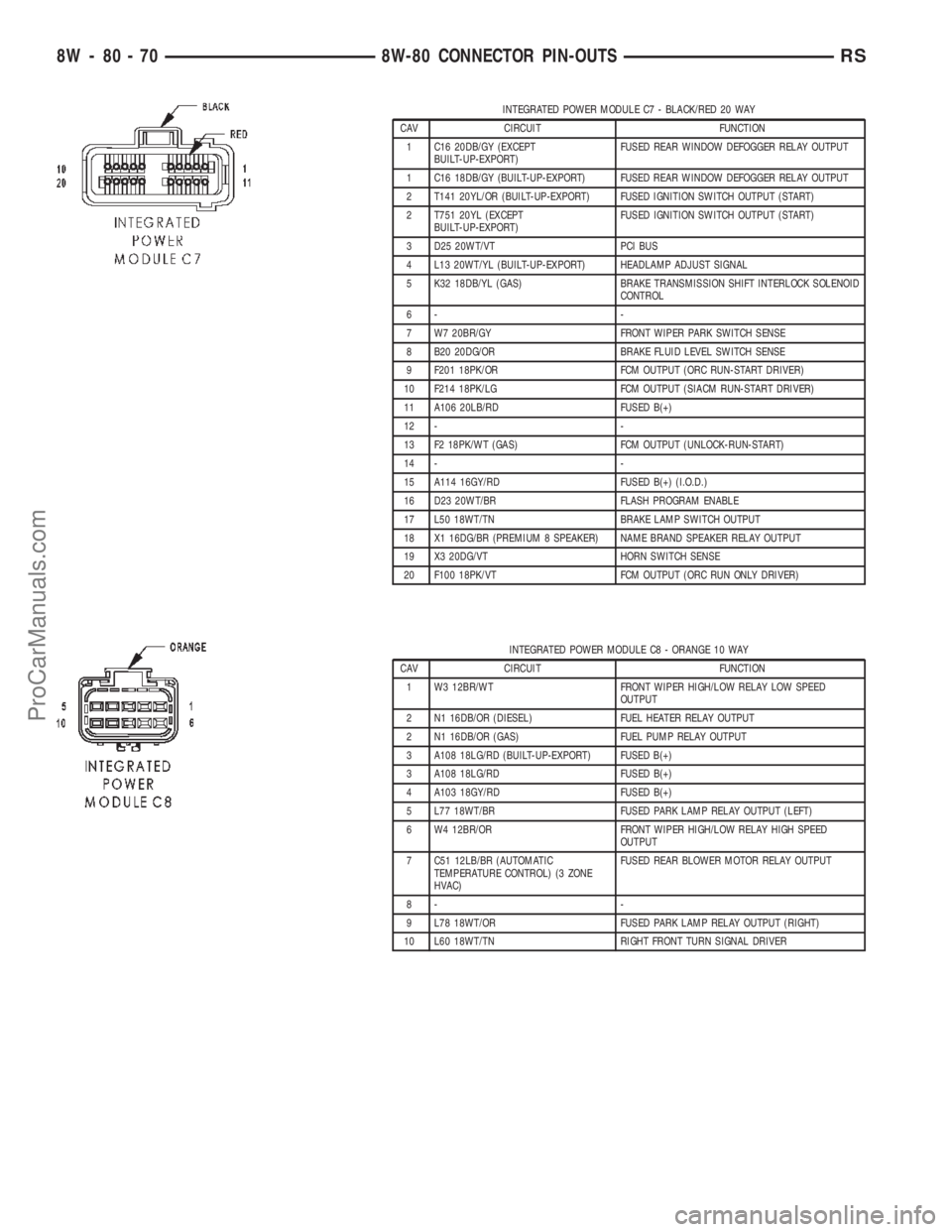
INTEGRATED POWER MODULE C7 - BLACK/RED 20 WAY
CAV CIRCUIT FUNCTION
1 C16 20DB/GY (EXCEPT
BUILT-UP-EXPORT)FUSED REAR WINDOW DEFOGGER RELAY OUTPUT
1 C16 18DB/GY (BUILT-UP-EXPORT) FUSED REAR WINDOW DEFOGGER RELAY OUTPUT
2 T141 20YL/OR (BUILT-UP-EXPORT) FUSED IGNITION SWITCH OUTPUT (START)
2 T751 20YL (EXCEPT
BUILT-UP-EXPORT)FUSED IGNITION SWITCH OUTPUT (START)
3 D25 20WT/VT PCI BUS
4 L13 20WT/YL (BUILT-UP-EXPORT) HEADLAMP ADJUST SIGNAL
5 K32 18DB/YL (GAS) BRAKE TRANSMISSION SHIFT INTERLOCK SOLENOID
CONTROL
6- -
7 W7 20BR/GY FRONT WIPER PARK SWITCH SENSE
8 B20 20DG/OR BRAKE FLUID LEVEL SWITCH SENSE
9 F201 18PK/OR FCM OUTPUT (ORC RUN-START DRIVER)
10 F214 18PK/LG FCM OUTPUT (SIACM RUN-START DRIVER)
11 A106 20LB/RD FUSED B(+)
12 - -
13 F2 18PK/WT (GAS) FCM OUTPUT (UNLOCK-RUN-START)
14 - -
15 A114 16GY/RD FUSED B(+) (I.O.D.)
16 D23 20WT/BR FLASH PROGRAM ENABLE
17 L50 18WT/TN BRAKE LAMP SWITCH OUTPUT
18 X1 16DG/BR (PREMIUM 8 SPEAKER) NAME BRAND SPEAKER RELAY OUTPUT
19 X3 20DG/VT HORN SWITCH SENSE
20 F100 18PK/VT FCM OUTPUT (ORC RUN ONLY DRIVER)
INTEGRATED POWER MODULE C8 - ORANGE 10 WAY
CAV CIRCUIT FUNCTION
1 W3 12BR/WT FRONT WIPER HIGH/LOW RELAY LOW SPEED
OUTPUT
2 N1 16DB/OR (DIESEL) FUEL HEATER RELAY OUTPUT
2 N1 16DB/OR (GAS) FUEL PUMP RELAY OUTPUT
3 A108 18LG/RD (BUILT-UP-EXPORT) FUSED B(+)
3 A108 18LG/RD FUSED B(+)
4 A103 18GY/RD FUSED B(+)
5 L77 18WT/BR FUSED PARK LAMP RELAY OUTPUT (LEFT)
6 W4 12BR/OR FRONT WIPER HIGH/LOW RELAY HIGH SPEED
OUTPUT
7 C51 12LB/BR (AUTOMATIC
TEMPERATURE CONTROL) (3 ZONE
HVAC)FUSED REAR BLOWER MOTOR RELAY OUTPUT
8- -
9 L78 18WT/OR FUSED PARK LAMP RELAY OUTPUT (RIGHT)
10 L60 18WT/TN RIGHT FRONT TURN SIGNAL DRIVER
8W - 80 - 70 8W-80 CONNECTOR PIN-OUTSRS
ProCarManuals.com