hood release CHRYSLER CARAVAN 2002 Service Manual
[x] Cancel search | Manufacturer: CHRYSLER, Model Year: 2002, Model line: CARAVAN, Model: CHRYSLER CARAVAN 2002Pages: 2399, PDF Size: 57.96 MB
Page 175 of 2399

(4) Tighten four booster mounting nuts and two
pedal bracket upper mounting bolts to 28 N´m (21 ft.
lbs.) torque.
(5) Install accelerator cable to pedal; install cable
retainer at accelerator pedal.
(6) Install booster input rod on brake pedal pin
and install a NEW retaining clip (Fig. 72).
(7) Install wiring harness in clips along pedal
bracket, then connect harness to pedal wiring har-
ness connector (Fig. 69).
(8) Install brake lamp switch bracket on pedal
assembly (Fig. 69). Tighten mounting nuts to 6 N´m
(50 in. lbs.) torque.(9) Install dash seal silencer shell over steering
column intermediate shaft and fasten in place (Fig.
68).
(10) Install the steering column on the mounting
studs. Install the two upper and two lower mounting
nuts. Tighten the upper, then lower mounting nuts to
12 N´m (105 in. lbs.) torque.
(11) Install the column shaft coupling onto the
intermediate shaft and install the pinch bolt (steer-
ing column should still be locked position it was
placed in during removal). Make sure the rounded
side of the intermediate shaft is matched to the cur-
vature of the coupling. Tighten the pinch bolt to 28
N´m (250 in. lbs.).
(12) Attach shift cable housing to bracket on col-
umn.
(13) Connect shift cable end to shift lever mecha-
nism pin (Fig. 66).
(14) Connect PRNDL cable to end of shift lever
mechanism pin and column bracket (Fig. 66).
(15) Connect column wiring harness connectors to
SKIM (if equipped), BTSI solenoid, ignition switch,
halo lamp, multi-function switch, and clockspring.
(16) Install the upper shroud (Refer to 19 -
STEERING/COLUMN/LOWER SHROUD - INSTAL-
LATION).
(17) If equipped, connect traction control off switch
wiring connector.
(18) Install upper shroud (with traction control off
switch if equipped) (Fig. 64).
(19) Connect adjustable pedal switch wiring con-
nector along left side of column (Fig. 65).
(20) Install the lower shroud with adjustable pedal
switch. Install screws fastening steering column
shrouds to steering column (Fig. 64).
CAUTION: Do not reuse the original brake lamp
switch. The switch can only be adjusted once. That
is during initial installation of the switch. If the
switch is not adjusted properly or has been
removed for some service, a new switch must be
installed and adjusted.
(21) Install and adjust NEW brake lamp switch.
(Refer to 8 - ELECTRICAL/LAMPS/LIGHTING -
EXTERIOR/BRAKE LAMP SWITCH - INSTALLA-
TION)
(22) Install instrument panel lower left reinforce-
ment (Fig. 63).
(23) Attach hood release to lower left reinforce-
ment.
(24) Install knee blocker reinforcement plate (Fig.
62).
(25) Connect parking brake release link to release
handle.
(26) Install data link diagnostic connector to
mounting hole in reinforcement plate.
Fig. 71 Booster Mounting (Typical)
1 - DASH BRACKET
2 - POWER BRAKE BOOSTER
3 - BRAKE PEDAL ASSEMBLY
Fig. 72 Retaining Pin Installed On Brake Pedal Pin
1 - BRAKE PEDAL
2 - RETAINING CLIP
3 - BOOSTER INPUT ROD
5 - 46 BRAKES - BASERS
PEDAL - ADJUSTABLE (Continued)
ProCarManuals.com
Page 399 of 2399

BATTERY TEMPERATURE
SENSOR
DESCRIPTION
The PCM incorporates a Battery Temperature Sen-
sor (BTS) on its circuit board.
OPERATION
The PCM uses the temperature of the battery area
to control the charge system voltage. This tempera-
ture, along with data from monitored line voltage, is
used by the PCM to vary the battery charging rate.
The system voltage is higher at cold temperatures
and is gradually reduced as temperature around the
battery increases.
The ambient temperature sensor is used to control
the battery voltage based upon ambient temperature
(approximation of battery temperature). The PCM
maintains the optimal output of the generator by
monitoring battery voltage and controlling it to a
range of 13.5 - 14.7 volts based on battery tempera-
ture.
The battery temperature sensor is also used for
OBD II diagnostics. Certain faults and OBD II mon-
itors are either enabled or disabled depending upon
the battery temperature sensor input (example: dis-
able purge and EGR, enable LDP). Most OBD II
monitors are disabled below 20ÉF.
REMOVAL
The battery temperature sensor is not serviced sep-
arately. If replacement is necessary, the PCM must
be replaced.
GENERATOR
DESCRIPTION
The generator is belt-driven by the engine. It is
serviced only as a complete assembly. The generator
produces DC voltage at the B+ terminal. If the gen-
erator is failed, the generator assembly subcompo-
nents (generator and decoupler pulley) must be
inspected for individual failure and replaced accord-
ingly.
OPERATION
As the energized rotor begins to rotate within the
generator, the spinning magnetic field induces a cur-
rent into the windings of the stator coil. Once the
generator begins producing sufficient current, it also
provides the current needed to energize the rotor.
The Y type stator winding connections deliver the
induced AC current to 3 positive and 3 negative
diodes for rectification. From the diodes, rectified DCcurrent is delivered to the vehicles electrical system
through the generator, battery, and ground terminals.
Excessive or abnormal noise emitting from the gen-
erator may be caused by:
²Worn, loose or defective bearings
²Loose or defective drive pulley (2.4L) or decou-
pler (3.3/3.8L)
²Incorrect, worn, damaged or misadjusted drive
belt
²Loose mounting bolts
²Misaligned drive pulley
²Defective stator or diode
²Damaged internal fins
REMOVAL
REMOVAL - 2.4L
(1) Release hood latch and open hood.
(2) Disconnect battery negative cable.
(3) Disconnect the Inlet Air Temperature sensor.
(4) Remove the Air Box, refer to the Engine/Air
Cleaner for more information.
(5) Remove the EVAP Purge solenoid from its
bracket and reposition.
(6) Disconnect the push-in field wire connector
from back of generator.
(7) Remove nut holding B+ wire terminal to back
of generator.
(8) Separate B+ terminal from generator.
(9) Remove accessory drive belt, refer to the Cool-
ing System section for proper procedures.
(10) Remove the generator.
REMOVAL - 3.3/3.8L
(1) Release hood latch and open hood.
(2) Disconnect battery negative cable.
(3) Disconnect the push-in field wire connector
from back of generator.
(4) Remove nut holding B+ wire terminal to back
of generator.
(5) Separate B+ terminal from generator.
(6) Raise vehicle and support.
(7) Remove the right front lower splash shield.
(8) Remove accessory drive belt, refer to the Cool-
ing System section for proper procedures.
(9) Remove the lower oil dip stick tube bolt (Fig.
2).
(10) Remove wiring harness from the oil dip stick
tube
(11) Remove the 3 mounting bolts.
(12) Lower vehicle.
(13) Remove oil dip stick tube from vehicle.
(14) Roll and remove the generator from vehicle
(Fig. 3).
8F - 24 CHARGINGRS
ProCarManuals.com
Page 401 of 2399
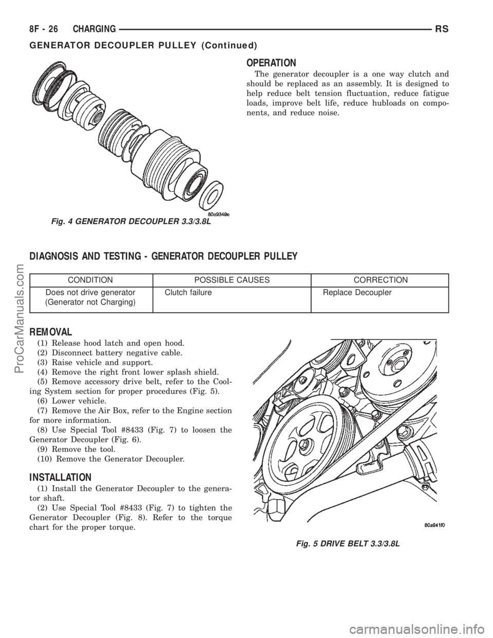
OPERATION
The generator decoupler is a one way clutch and
should be replaced as an assembly. It is designed to
help reduce belt tension fluctuation, reduce fatigue
loads, improve belt life, reduce hubloads on compo-
nents, and reduce noise.
DIAGNOSIS AND TESTING - GENERATOR DECOUPLER PULLEY
CONDITION POSSIBLE CAUSES CORRECTION
Does not drive generator
(Generator not Charging)Clutch failure Replace Decoupler
REMOVAL
(1) Release hood latch and open hood.
(2) Disconnect battery negative cable.
(3) Raise vehicle and support.
(4) Remove the right front lower splash shield.
(5) Remove accessory drive belt, refer to the Cool-
ing System section for proper procedures (Fig. 5).
(6) Lower vehicle.
(7) Remove the Air Box, refer to the Engine section
for more information.
(8) Use Special Tool #8433 (Fig. 7) to loosen the
Generator Decoupler (Fig. 6).
(9) Remove the tool.
(10) Remove the Generator Decoupler.
INSTALLATION
(1) Install the Generator Decoupler to the genera-
tor shaft.
(2) Use Special Tool #8433 (Fig. 7) to tighten the
Generator Decoupler (Fig. 8). Refer to the torque
chart for the proper torque.
Fig. 4 GENERATOR DECOUPLER 3.3/3.8L
Fig. 5 DRIVE BELT 3.3/3.8L
8F - 26 CHARGINGRS
GENERATOR DECOUPLER PULLEY (Continued)
ProCarManuals.com
Page 410 of 2399
STARTER MOTOR
REMOVAL
REMOVAL - 2.4L
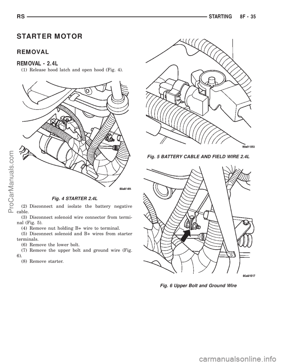
(1) Release hood latch and open hood (Fig. 4).
(2) Disconnect and isolate the battery negative
cable.
(3) Disconnect solenoid wire connector from termi-
nal (Fig. 5).
(4) Remove nut holding B+ wire to terminal.
(5) Disconnect solenoid and B+ wires from starter
terminals.
(6) Remove the lower bolt.
(7) Remove the upper bolt and ground wire (Fig.
6).
(8) Remove starter.
Fig. 4 STARTER 2.4L
Fig. 5 BATTERY CABLE AND FIELD WIRE 2.4L
Fig. 6 Upper Bolt and Ground Wire
RSSTARTING8F-35
ProCarManuals.com
Page 411 of 2399
REMOVAL - 3.3/3.8L
(1) Release hood latch and open hood.
(2) Disconnect and isolate the battery negative
cable.
(3) Hoist and support vehicle on safety stands.
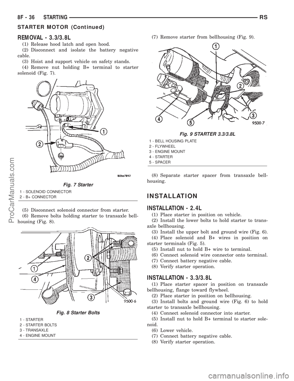
(4) Remove nut holding B+ terminal to starter
solenoid (Fig. 7).
(5) Disconnect solenoid connector from starter.
(6) Remove bolts holding starter to transaxle bell-
housing (Fig. 8).(7) Remove starter from bellhousing (Fig. 9).
(8) Separate starter spacer from transaxle bell-
housing.
INSTALLATION
INSTALLATION - 2.4L
(1) Place starter in position on vehicle.
(2) Install the lower bolts to hold starter to trans-
axle bellhousing.
(3) Install the upper bolt and ground wire (Fig. 6).
(4) Place solenoid and B+ wires in position on
starter terminals (Fig. 5).
(5) Install nut to hold B+ wire to terminal.
(6) Connect solenoid wire connector onto terminal.
(7) Connect battery negative cable.
(8) Verify starter operation.
INSTALLATION - 3.3/3.8L
(1) Place starter spacer in position on transaxle
bellhousing, flange toward flywheel.
(2) Place starter in position on bellhousing.
(3) Install bolts and ground wire (Fig. 6) to hold
starter to transaxle bellhousing.
(4) Connect solenoid connector into starter.
(5) Install nut to hold B+ terminal to starter sole-
noid.
(6) Lower vehicle.
(7) Connect battery negative cable.
(8) Verify starter operation.
Fig. 7 Starter
1 - SOLENOID CONNECTOR
2 - B+ CONNECTOR
Fig. 8 Starter Bolts
1-STARTER
2 - STARTER BOLTS
3 - TRANSAXLE
4 - ENGINE MOUNT
Fig. 9 STARTER 3.3/3.8L
1 - BELL HOUSING PLATE
2 - FLYWHEEL
3 - ENGINE MOUNT
4-STARTER
5 - SPACER
8F - 36 STARTINGRS
STARTER MOTOR (Continued)
ProCarManuals.com
Page 434 of 2399

BATTERY TEMPERATURE
SENSOR
DESCRIPTION
The PCM incorporates a Battery Temperature Sen-
sor (BTS) on its circuit board.
OPERATION
The PCM uses the temperature of the battery area
to control the charge system voltage. This tempera-
ture, along with data from monitored line voltage, is
used by the PCM to vary the battery charging rate.
The system voltage is higher at cold temperatures
and is gradually reduced as temperature around the
battery increases.
The ambient temperature sensor is used to control
the battery voltage based upon ambient temperature
(approximation of battery temperature). The PCM
maintains the optimal output of the generator by
monitoring battery voltage and controlling it to a
range of 13.5 - 14.7 volts based on battery tempera-
ture.
The battery temperature sensor is also used for
OBD II diagnostics. Certain faults and OBD II mon-
itors are either enabled or disabled depending upon
the battery temperature sensor input (example: dis-
able purge and EGR, enable LDP). Most OBD II
monitors are disabled below 20ÉF.
REMOVAL
The battery temperature sensor is not serviced sep-
arately. If replacement is necessary, the PCM must
be replaced.
GENERATOR
DESCRIPTION
The generator is belt-driven by the engine. It is
serviced only as a complete assembly. The generator
produces DC voltage at the B+ terminal. If the gen-
erator is failed, the generator assembly subcompo-
nents (generator and decoupler pulley) must be
inspected for individual failure and replaced accord-
ingly.
OPERATION
As the energized rotor begins to rotate within the
generator, the spinning magnetic field induces a cur-
rent into the windings of the stator coil. Once the
generator begins producing sufficient current, it also
provides the current needed to energize the rotor.
The Y type stator winding connections deliver the
induced AC current to 3 positive and 3 negative
diodes for rectification. From the diodes, rectified DC
current is delivered to the vehicles electrical system
through the generator, battery, and ground terminals.
Excessive or abnormal noise emitting from the gen-
erator may be caused by:
²Worn, loose or defective bearings
²Loose or defective drive pulley (2.4L) or decou-
pler (3.3/3.8L)
²Incorrect, worn, damaged or misadjusted drive
belt
²Loose mounting bolts
²Misaligned drive pulley
²Defective stator or diode
²Damaged internal fins
REMOVAL
REMOVAL - 2.4L
(1) Release hood latch and open hood.
(2) Disconnect battery negative cable.
(3) Disconnect the Inlet Air Temperature sensor.
(4) Remove the Air Box, refer to the Engine/Air
Cleaner for more information.
(5) Remove the EVAP Purge solenoid from its
bracket and reposition.
(6) Disconnect the push-in field wire connector
from back of generator.
(7) Remove nut holding B+ wire terminal to back
of generator.
(8) Separate B+ terminal from generator.
(9) Remove accessory drive belt, refer to the Cool-
ing System section for proper procedures.
(10) Remove the generator.
RGCHARGING8Fa-23
ProCarManuals.com
Page 436 of 2399
(6) Lower vehicle.
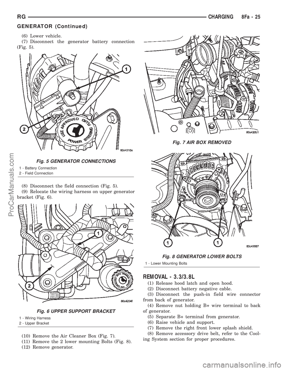
(7) Disconnect the generator battery connection
(Fig. 5).
(8) Disconnect the field connection (Fig. 5).
(9) Relocate the wiring harness on upper generator
bracket (Fig. 6).
(10) Remove the Air Cleaner Box (Fig. 7).
(11) Remove the 2 lower mounting Bolts (Fig. 8).
(12) Remove generator.
REMOVAL - 3.3/3.8L
(1) Release hood latch and open hood.
(2) Disconnect battery negative cable.
(3) Disconnect the push-in field wire connector
from back of generator.
(4) Remove nut holding B+ wire terminal to back
of generator.
(5) Separate B+ terminal from generator.
(6) Raise vehicle and support.
(7) Remove the right front lower splash shield.
(8) Remove accessory drive belt, refer to the Cool-
ing System section for proper procedures.
Fig. 5 GENERATOR CONNECTIONS
1 - Battery Connection
2 - Field Connection
Fig. 6 UPPER SUPPORT BRACKET
1 - Wiring Harness
2 - Upper Bracket
Fig. 7 AIR BOX REMOVED
Fig. 8 GENERATOR LOWER BOLTS
1 - Lower Mounting Bolts
RGCHARGING8Fa-25
GENERATOR (Continued)
ProCarManuals.com
Page 440 of 2399
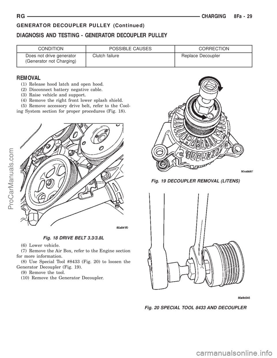
DIAGNOSIS AND TESTING - GENERATOR DECOUPLER PULLEY
CONDITION POSSIBLE CAUSES CORRECTION
Does not drive generator
(Generator not Charging)Clutch failure Replace Decoupler
REMOVAL
(1) Release hood latch and open hood.
(2) Disconnect battery negative cable.
(3) Raise vehicle and support.
(4) Remove the right front lower splash shield.
(5) Remove accessory drive belt, refer to the Cool-
ing System section for proper procedures (Fig. 18).
(6) Lower vehicle.
(7) Remove the Air Box, refer to the Engine section
for more information.
(8) Use Special Tool #8433 (Fig. 20) to loosen the
Generator Decoupler (Fig. 19).
(9) Remove the tool.
(10) Remove the Generator Decoupler.
Fig. 18 DRIVE BELT 3.3/3.8L
Fig. 19 DECOUPLER REMOVAL (LITENS)
Fig. 20 SPECIAL TOOL 8433 AND DECOUPLER
RGCHARGING8Fa-29
GENERATOR DECOUPLER PULLEY (Continued)
ProCarManuals.com
Page 449 of 2399
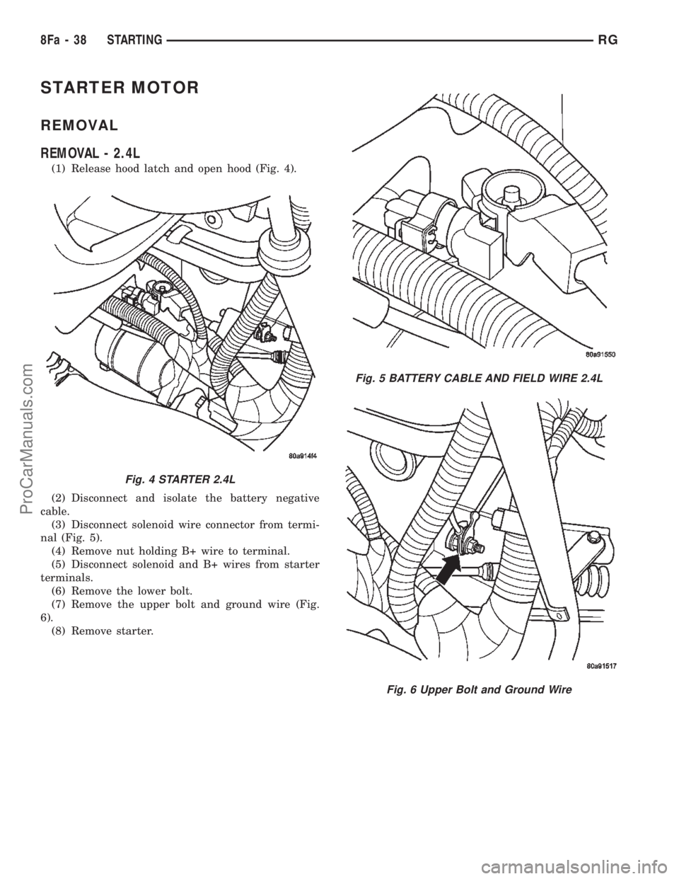
STARTER MOTOR
REMOVAL
REMOVAL - 2.4L
(1) Release hood latch and open hood (Fig. 4).
(2) Disconnect and isolate the battery negative
cable.
(3) Disconnect solenoid wire connector from termi-
nal (Fig. 5).
(4) Remove nut holding B+ wire to terminal.
(5) Disconnect solenoid and B+ wires from starter
terminals.
(6) Remove the lower bolt.
(7) Remove the upper bolt and ground wire (Fig.
6).
(8) Remove starter.
Fig. 4 STARTER 2.4L
Fig. 5 BATTERY CABLE AND FIELD WIRE 2.4L
Fig. 6 Upper Bolt and Ground Wire
8Fa - 38 STARTINGRG
ProCarManuals.com
Page 450 of 2399
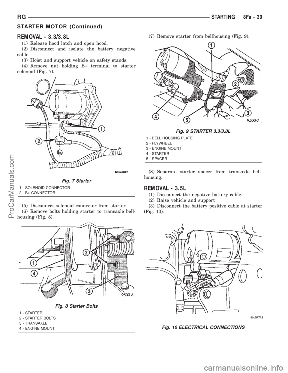
REMOVAL - 3.3/3.8L
(1) Release hood latch and open hood.
(2) Disconnect and isolate the battery negative
cable.
(3) Hoist and support vehicle on safety stands.
(4) Remove nut holding B+ terminal to starter
solenoid (Fig. 7).
(5) Disconnect solenoid connector from starter.
(6) Remove bolts holding starter to transaxle bell-
housing (Fig. 8).(7) Remove starter from bellhousing (Fig. 9).
(8) Separate starter spacer from transaxle bell-
housing.
REMOVAL - 3.5L
(1) Disconnect the negative battery cable.
(2) Raise vehicle and support
(3) Disconnect the battery positive cable at starter
(Fig. 10).
Fig. 7 Starter
1 - SOLENOID CONNECTOR
2 - B+ CONNECTOR
Fig. 8 Starter Bolts
1-STARTER
2 - STARTER BOLTS
3 - TRANSAXLE
4 - ENGINE MOUNT
Fig. 9 STARTER 3.3/3.8L
1 - BELL HOUSING PLATE
2 - FLYWHEEL
3 - ENGINE MOUNT
4-STARTER
5 - SPACER
Fig. 10 ELECTRICAL CONNECTIONS
RGSTARTING8Fa-39
STARTER MOTOR (Continued)
ProCarManuals.com