length CHRYSLER CARAVAN 2002 Service Manual
[x] Cancel search | Manufacturer: CHRYSLER, Model Year: 2002, Model line: CARAVAN, Model: CHRYSLER CARAVAN 2002Pages: 2399, PDF Size: 57.96 MB
Page 36 of 2399
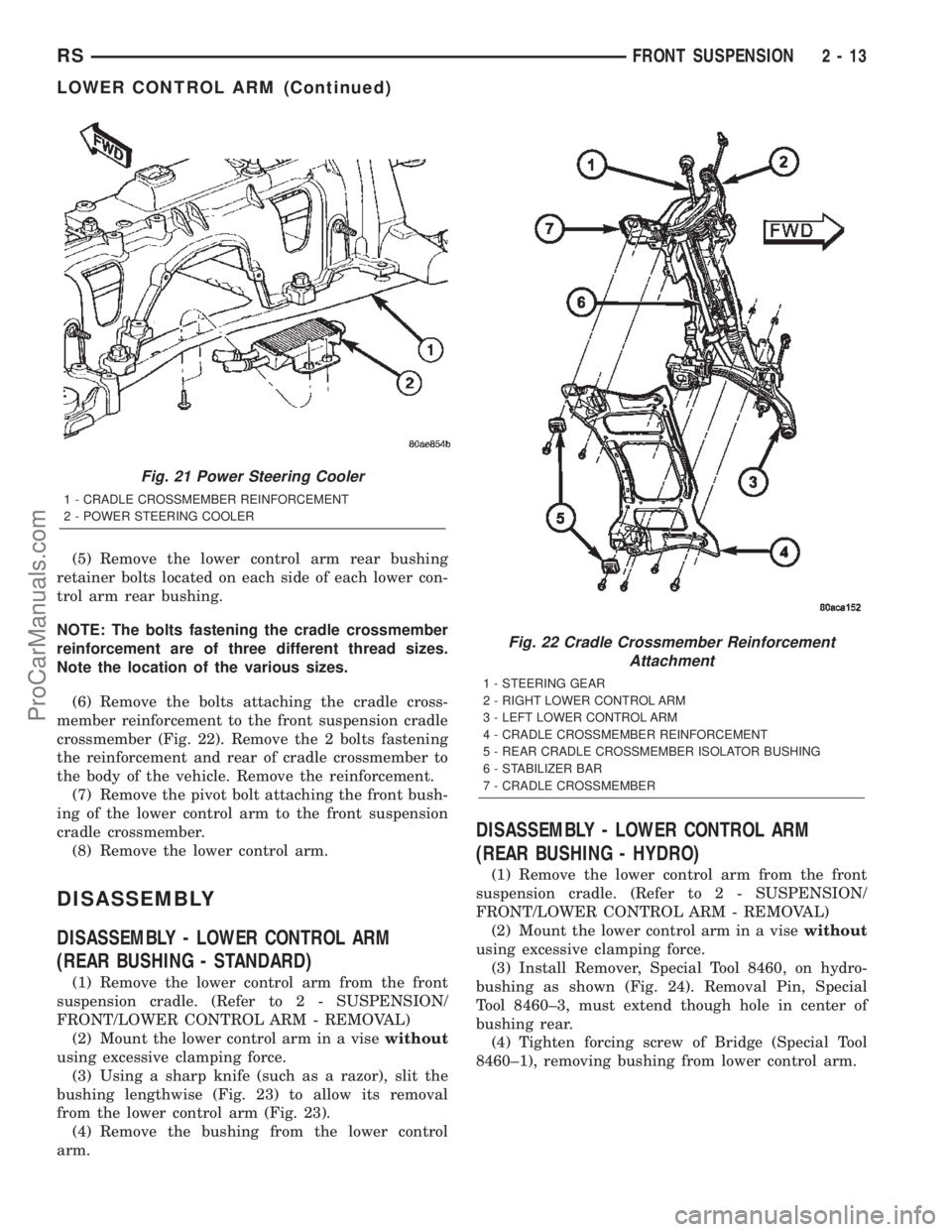
(5) Remove the lower control arm rear bushing
retainer bolts located on each side of each lower con-
trol arm rear bushing.
NOTE: The bolts fastening the cradle crossmember
reinforcement are of three different thread sizes.
Note the location of the various sizes.
(6) Remove the bolts attaching the cradle cross-
member reinforcement to the front suspension cradle
crossmember (Fig. 22). Remove the 2 bolts fastening
the reinforcement and rear of cradle crossmember to
the body of the vehicle. Remove the reinforcement.
(7) Remove the pivot bolt attaching the front bush-
ing of the lower control arm to the front suspension
cradle crossmember.
(8) Remove the lower control arm.
DISASSEMBLY
DISASSEMBLY - LOWER CONTROL ARM
(REAR BUSHING - STANDARD)
(1) Remove the lower control arm from the front
suspension cradle. (Refer to 2 - SUSPENSION/
FRONT/LOWER CONTROL ARM - REMOVAL)
(2) Mount the lower control arm in a visewithout
using excessive clamping force.
(3) Using a sharp knife (such as a razor), slit the
bushing lengthwise (Fig. 23) to allow its removal
from the lower control arm (Fig. 23).
(4) Remove the bushing from the lower control
arm.
DISASSEMBLY - LOWER CONTROL ARM
(REAR BUSHING - HYDRO)
(1) Remove the lower control arm from the front
suspension cradle. (Refer to 2 - SUSPENSION/
FRONT/LOWER CONTROL ARM - REMOVAL)
(2) Mount the lower control arm in a visewithout
using excessive clamping force.
(3) Install Remover, Special Tool 8460, on hydro-
bushing as shown (Fig. 24). Removal Pin, Special
Tool 8460±3, must extend though hole in center of
bushing rear.
(4) Tighten forcing screw of Bridge (Special Tool
8460±1), removing bushing from lower control arm.
Fig. 21 Power Steering Cooler
1 - CRADLE CROSSMEMBER REINFORCEMENT
2 - POWER STEERING COOLER
Fig. 22 Cradle Crossmember Reinforcement
Attachment
1 - STEERING GEAR
2 - RIGHT LOWER CONTROL ARM
3 - LEFT LOWER CONTROL ARM
4 - CRADLE CROSSMEMBER REINFORCEMENT
5 - REAR CRADLE CROSSMEMBER ISOLATOR BUSHING
6 - STABILIZER BAR
7 - CRADLE CROSSMEMBER
RSFRONT SUSPENSION2-13
LOWER CONTROL ARM (Continued)
ProCarManuals.com
Page 47 of 2399

(5) If the pivot bearing has been removed from the
upper seat, install the pivot bearing on the top of the
upper spring seat (Fig. 48). The bearing must be
installed on upper seat with the smaller diameter
side of the pivot bearing toward the spring seat. Be
sure the pivot bearing is sitting flat on the spring
seat once mounted.
(6) Install the spring isolator on the lower spring
seat of the strut (Fig. 38).
(7) Install the jounce bumper on the strut shaft
(Fig. 38). The jounce bumper is to be installed with
the small end pointing downward.
(8) Install the dust shield on the strut. Collapse
and stretch the dust shield down over the top of the
jounce bumper until the dust shield snaps into theslot on the jounce bumper. The jounce bumper will be
at the top of the inner dust boot. Return the dust
shield to its fully extended length.
(9) Install the strut through the bottom of the coil
spring until the lower spring seat contacts the lower
end of the coil spring. The clevis bracket on the strut
should point straight outward away from the com-
pressor (to the 6 o'clock position). This position
should be within 5É of the lower end tip of the coil
spring (Fig. 49). If necessary, reposition the strut or
coil spring in the compressor so both of these line up
straight outward away from the compressor (to the 6
o'clock position). Install the clamp to hold the strut
and coil together.
(10) Install the strut mount over the strut shaft
and onto the top of the pivot bearing and upper seat
as shown (Fig. 44). Loosely install the retaining nut
on the strut shaft.
(11) Install Strut Nut Socket (on the end of a
torque wrench), Special Tool 6864, on the strut shaft
retaining nut (Fig. 45). Next, install a 10 mm socket
on the hex on the end of the strut shaft. While hold-
ing the strut shaft from turning, tighten the strut
shaft retaining nut to a torque of 100 N´m (75 ft.
lbs.).
NOTE: Before releasing the tension the compressor
has on the spring, using the following figure as ref-
erence (Fig. 50), make sure the upper spring seat,
coil spring and strut clevis bracket are all lined up
properly (within 5É of one another).
Fig. 47 Hook Placement On Upper Seat
1 - HOOKS POSITIONED 1 INCH FROM EDGE
2 - PIVOT BEARING AND UPPER SEAT
Fig. 48 Pivot Bearing Installation
1 - PIVOT BEARING
2 - UPPER SEAT
Fig. 49 Coil Spring Positioning
1 - FRONT OF VEHICLE
2 - END OF RIGHT COIL SPRING AT STRUT LOWER SEAT
3 - LOWER SEATS OF STRUTS
4 - STRUT CLEVIS BRACKETS
5 - END OF LEFT COIL SPRING AT STRUT LOWER SEAT
2 - 24 FRONT SUSPENSIONRS
STRUT (Continued)
ProCarManuals.com
Page 80 of 2399
DIFFERENTIAL & DRIVELINE
TABLE OF CONTENTS
page page
HALF SHAFT - FRONT.....................1
HALF SHAFT - REAR.....................14PROPELLER SHAFT.....................22
REAR DRIVELINE MODULE................24
HALF SHAFT - FRONT
TABLE OF CONTENTS
page page
HALF SHAFT - FRONT
DESCRIPTION..........................1
DIAGNOSIS AND TESTING - HALF SHAFT.....1
REMOVAL.............................2
INSTALLATION..........................4
SPECIFICATIONS - HALF SHAFT - FRONT....6
CV BOOT - INNER
REMOVAL.............................6INSTALLATION..........................6
CV BOOT - OUTER
REMOVAL.............................10
INSTALLATION.........................10
OUTER CV JOINT BEARING SHIELD
REMOVAL.............................13
INSTALLATION.........................13
HALF SHAFT - FRONT
DESCRIPTION
All vehicles use an unequal length half shaft sys-
tem (Fig. 1).
The left half shaft uses a tuned rubber damper
weight. When replacing the left half shaft, be sure
the replacement half shaft has the same damper
weight as the original.
All half shaft assemblies use the same type of
inner and outer joints. The inner joint of both half
shaft assemblies is a tripod joint, and the outer joint
of both half shaft assemblies is a Rzeppa joint. Both
tripod joints and Rzeppa joints are true constant
velocity (CV) joint assemblies. The inner tripod joint
allows for the changes in half shaft length through
the jounce and rebound travel of the front suspen-
sion.
On vehicles equipped with ABS brakes, the outer
CV joint is equipped with a tone wheel used to deter-
mine vehicle speed for ABS brake operation.
The inner tripod joint of both half shafts is splined
into the transaxle side gears. The inner tripod joints
are retained in the side gears of the transaxle using
a snap ring located in the stub shaft of the tripod
joint. The outer CV joint has a stub shaft that issplined into the wheel hub and retained by a steel
hub nut.DIAGNOSIS AND TESTING - HALF SHAFT
VEHICLE INSPECTION
(1) Check for grease in the vicinity of the inboard
tripod joint and outboard CV joint; this is a sign of
inner or outer joint seal boot or seal boot clamp dam-
age.
NOISE AND/OR VIBRATION IN TURNS
A clicking noise and/or a vibration in turns could
be caused by one of the following conditions:
²Damaged outer CV or inner tripod joint seal
boot or seal boot clamps. This will result in the loss
and/or contamination of the joint grease, resulting in
inadequate lubrication of the joint.
²Noise may also be caused by another component
of the vehicle coming in contact with the half shafts.
CLUNKING NOISE DURING ACCELERATION
This noise may be a result of one of the following
conditions:
²A torn seal boot on the inner or outer joint of the
half shaft assembly.
RSDIFFERENTIAL & DRIVELINE3-1
ProCarManuals.com
Page 81 of 2399

²A loose or missing clamp on the inner or outer
joint of the half shaft assembly.
²A damaged or worn half shaft CV joint.
SHUDDER OR VIBRATION DURING ACCELERATION
This problem could be a result of:
²A worn or damaged half shaft inner tripod joint.
²A sticking tripod joint spider assembly (inner tri-
pod joint only).
²Improper wheel alignment. (Refer to 2 - SUS-
PENSION/WHEEL ALIGNMENT - STANDARD
PROCEDURE)
VIBRATION AT HIGHWAY SPEEDS
This problem could be a result of:
²Foreign material (mud, etc.) packed on the back-
side of the wheel(s).
²Out of balance tires or wheels. (Refer to 22 -
TIRES/WHEELS - STANDARD PROCEDURE)
²Improper tire and/or wheel runout. (Refer to 22 -
TIRES/WHEELS - DIAGNOSIS AND TESTING)
REMOVAL
(1) Raise vehicle.(2) Remove the cotter pin and nut lock (Fig. 2)
from the end of the half shaft.
Fig. 1 Unequal Length Half Shaft System
1 - STUB AXLE 8 - OUTER C/V JOINT
2 - OUTER C/V JOINT 9 - RIGHT HALFSHAFT
3 - OUTER C/V JOINT BOOT 10 - INNER TRIPOD JOINT BOOT
4 - TUNED RUBBER DAMPER WEIGHT 11 - INNER TRIPOD JOINT
5 - INTERCONNECTING SHAFT 12 - INNER TRIPOD JOINT
6 - OUTER C/V JOINT BOOT 13 - INNER TRIPOD JOINT BOOT
7 - STUB AXLE 14 - INTERCONNECTING SHAFT LEFT HALFSHAFT
Fig. 2 Half Shaft Retaining Nut
1 - HUB/BEARING
2 - NUT LOCK
3 - COTTER PIN
4 - STUB AXLE
3 - 2 HALF SHAFT - FRONTRS
HALF SHAFT - FRONT (Continued)
ProCarManuals.com
Page 93 of 2399
HALF SHAFT - REAR
TABLE OF CONTENTS
page page
HALF SHAFT - REAR
DESCRIPTION.........................14
DIAGNOSIS AND TESTING - HALF SHAFT....14
REMOVAL.............................15
INSTALLATION.........................15SPECIFICATIONS - HALF SHAFT - FRONT . . . 16
CV BOOT - INNER/OUTER
REMOVAL.............................17
INSTALLATION.........................18
HALF SHAFT - REAR
DESCRIPTION
The inner and outer joints of both half shaft
assemblies are tripod joints. The tripod joints are
true constant velocity (CV) joint assemblies, which
allow for the changes in half shaft length through
the jounce and rebound travel of the rear suspension.
On vehicles equipped with ABS brakes, the outer
CV joint is equipped with a tone wheel used to deter-
mine vehicle speed for ABS brake operation.
The inner tripod joint of both half shafts is bolted
rear differential assembly's output flanges. The outer
CV joint has a stub shaft that is splined into the
wheel hub and retained by a steel hub nut.
DIAGNOSIS AND TESTING - HALF SHAFT
VEHICLE INSPECTION
(1) Check for grease in the vicinity of the inboard
tripod joint and outboard CV joint; this is a sign of
inner or outer joint seal boot or seal boot clamp dam-
age.
NOISE AND/OR VIBRATION IN TURNS
A clicking noise and/or a vibration in turns could
be caused by one of the following conditions:
²Damaged outer CV or inner tripod joint seal
boot or seal boot clamps. This will result in the loss
and/or contamination of the joint grease, resulting in
inadequate lubrication of the joint.²Noise may also be caused by another component
of the vehicle coming in contact with the half shafts.
CLUNKING NOISE DURING ACCELERATION
This noise may be a result of one of the following
conditions:
²A torn seal boot on the inner or outer joint of the
half shaft assembly.
²A loose or missing clamp on the inner or outer
joint of the half shaft assembly.
²A damaged or worn half shaft CV joint.
SHUDDER OR VIBRATION DURING ACCELERATION
This problem could be a result of:
²A worn or damaged half shaft inner tripod joint.
²A sticking tripod joint spider assembly (inner tri-
pod joint only).
²Improper wheel alignment. (Refer to 2 - SUS-
PENSION/WHEEL ALIGNMENT - STANDARD
PROCEDURE)
VIBRATION AT HIGHWAY SPEEDS
This problem could be a result of:
²Foreign material (mud, etc.) packed on the back-
side of the wheel(s).
²Out of balance tires or wheels. (Refer to 22 -
TIRES/WHEELS - STANDARD PROCEDURE)
²Improper tire and/or wheel runout. (Refer to 22 -
TIRES/WHEELS - DIAGNOSIS AND TESTING)
3 - 14 HALF SHAFT - REARRS
ProCarManuals.com
Page 157 of 2399
CLEANING - CALIPER
WARNING: DUST AND DIRT ACCUMULATING ON
BRAKE PARTS DURING NORMAL USE MAY CON-
TAIN ASBESTOS FIBERS FROM PRODUCTION OR
AFTERMARKET BRAKE LININGS. BREATHING
EXCESSIVE CONCENTRATIONS OF ASBESTOS
FIBERS CAN CAUSE SERIOUS BODILY HARM.
EXERCISE CARE WHEN SERVICING BRAKE
PARTS. DO NOT SAND OR GRIND BRAKE LINING
UNLESS EQUIPMENT USED IS DESIGNED TO CON-
TAIN THE DUST RESIDUE. DO NOT CLEAN BRAKE
PARTS WITH COMPRESSED AIR OR BY DRY
BRUSHING. CLEANING SHOULD BE DONE BY
DAMPENING THE BRAKE COMPONENTS WITH A
FINE MIST OF WATER, THEN WIPING THE BRAKE
COMPONENTS CLEAN WITH A DAMPENED CLOTH.
DISPOSE OF CLOTH AND ALL RESIDUE CONTAIN-
ING ASBESTOS FIBERS IN AN IMPERMEABLE
CONTAINER WITH THE APPROPRIATE LABEL. FOL-
LOW PRACTICES PRESCRIBED BY THE OCCUPA-
TIONAL SAFETY AND HEALTH ADMINISTRATION
(OSHA) AND THE ENVIRONMENTAL PROTECTION
AGENCY (EPA) FOR THE HANDLING, PROCESSING,
AND DISPOSING OF DUST OR DEBRIS THAT MAY
CONTAIN ASBESTOS FIBERS.
To clean or flush the internal passages of the brake
caliper, use fresh brake fluid or MopartNon-Chlori-
nated Brake Parts Cleaner. Never use gasoline, ker-osene, alcohol, oil, transmission fluid or any fluid
containing mineral oil to clean the caliper. These flu-
ids will damage rubber cups and seals.
INSPECTION - CALIPER
Inspect the disc brake caliper for the following:
²Brake fluid leaks in and around boot area and
inboard lining
²Ruptures, brittleness or damage to the piston
dust boot
²Damaged, dry or brittle guide pin dust boots
If caliper fails inspection, disassemble and recondi-
tion caliper, replacing the seals and dust boots.
ASSEMBLY
ASSEMBLY - CALIPER GUIDE PIN BUSHINGS
(DISC/DISC BRAKES)
(1) Fold the guide pin bushing in half lengthwise.
NOTE: To avoid damage to the bushing, do not use
a sharp object to install the guide pin bushing.
(2) Insert the folded bushing into the caliper
mounting boss using your fingers from the rear of
the caliper.
(3) Unfold the bushing using your fingers or a
wooden dowel until the bushing is fully seated into
the caliper housing. The bushing flanges should be
seated evenly on both sides of the bushing hole.
(4) Lubricate inside surfaces of bushing using
MopartDielectric Grease or equivalent.
(5) Repeat the procedure for remaining bushing.
ASSEMBLY - CALIPER PISTON AND SEAL
NOTE: Never use an old piston seal.
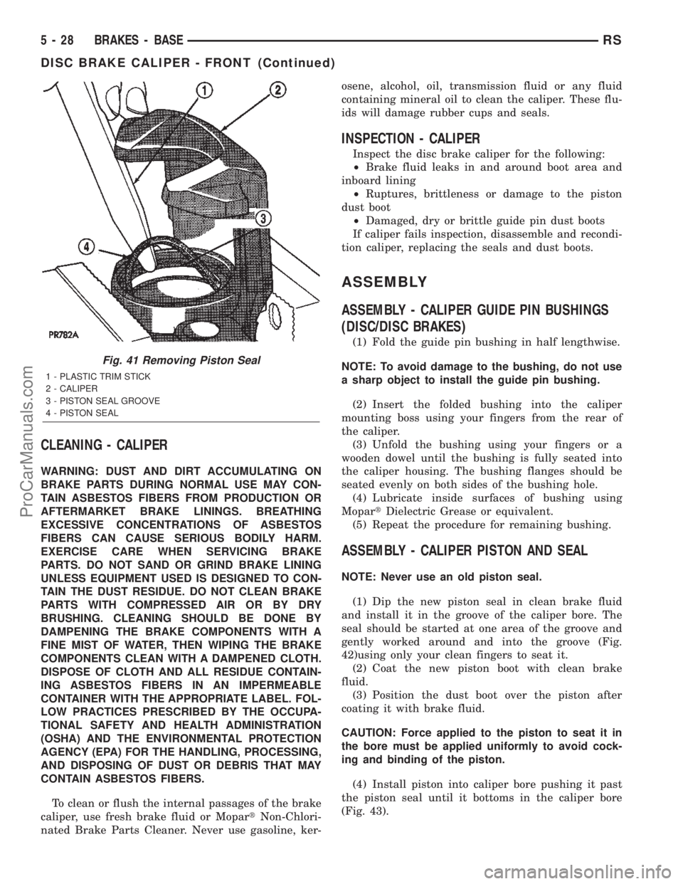
(1) Dip the new piston seal in clean brake fluid
and install it in the groove of the caliper bore. The
seal should be started at one area of the groove and
gently worked around and into the groove (Fig.
42)using only your clean fingers to seat it.
(2) Coat the new piston boot with clean brake
fluid.
(3) Position the dust boot over the piston after
coating it with brake fluid.
CAUTION: Force applied to the piston to seat it in
the bore must be applied uniformly to avoid cock-
ing and binding of the piston.
(4) Install piston into caliper bore pushing it past
the piston seal until it bottoms in the caliper bore
(Fig. 43).
Fig. 41 Removing Piston Seal
1 - PLASTIC TRIM STICK
2 - CALIPER
3 - PISTON SEAL GROOVE
4 - PISTON SEAL
5 - 28 BRAKES - BASERS
DISC BRAKE CALIPER - FRONT (Continued)
ProCarManuals.com
Page 323 of 2399
ANTENNA BODY AND CABLE
DESCRIPTION
All models use a fixed-length stainless steel rod-
type antenna mast, installed at the right front fender
of the vehicle. The antenna mast is connected to the
center wire of the coaxial antenna cable, and is not
grounded to any part of the vehicle.
OPERATION
To minimize static, the antenna base must have a
good ground. The coaxial antenna cable shield (the
outer wire mesh of the cable) is grounded to the
antenna base and the radio chassis.
The antenna coaxial cable has an additional dis-
connect, located near the right end of the instrument
panel. This additional disconnect allows the instru-
ment panel assembly to be removed and installed
without removing the radio.
The factory-installed Electronically Tuned Radios
(ETRs) automatically compensate for radio antenna
trim. Therefore, no antenna trimmer adjustment is
required or possible when replacing the receiver or
the antenna.
DIAGNOSIS AND TESTING - ANTENNA BODY
AND CABLE
WARNING: ON VEHICLES EQUIPPED WITH AIR-
BAGS, REFER TO ELECTRICAL, RESTRAINTS
BEFORE ATTEMPTING ANY STEERING WHEEL,
STEERING COLUMN, OR INSTRUMENT PANEL
COMPONENT DIAGNOSIS OR SERVICE. FAILURE
TO TAKE THE PROPER PRECAUTIONS COULD
RESULT IN ACCIDENTAL AIRBAG DEPLOYMENT
AND POSSIBLE PERSONAL INJURY.
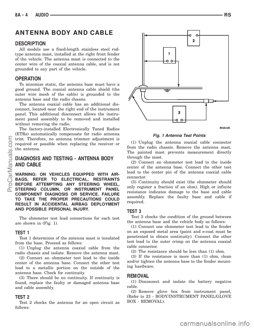
The ohmmeter test lead connections for each test
are shown in (Fig. 1).
TEST 1
Test 1 determines of the antenna mast is insulated
from the base. Proceed as follows:
(1) Unplug the antenna coaxial cable from the
radio chassis and isolate. Remove the antenna mast.
(2) Connect an ohmmeter test lead to the inside
center of the antenna base. Connect the other test
lead to a metallic portion on the outside of the
antenna base. Check for continuity.
(3) There should be no continuity. If continuity is
found, replace the faulty or damaged antenna base
and cable assembly.
TEST 2
Test 2 checks the antenna for an open circuit as
follows:(1) Unplug the antenna coaxial cable connector
from the radio chassis. Remove the antenna mast.
The painted mast prevents measurement directly
through the mast.
(2) Connect an ohmmeter test lead to the inside
center of the antenna base. Connect the other test
lead to the center pin of the antenna coaxial cable
connector.
(3) Continuity should exist (the ohmmeter should
only register a fraction of an ohm). High or infinite
resistance indicates damage to the base and cable
assembly. Replace the faulty base and cable if
required.
TEST 3
Test 3 checks the condition of the ground between
the antenna base and the vehicle body as follows:
(1) Connect one ohmmeter test lead to the fender
on an exposed metal area (paint and e-coat must be
penetrated to obtain continuity). Connect the other
test lead to the outer crimp on the antenna coaxial
cable connector.
(2) The resistance should be less than (1) ohm.
(3) If the resistance is more than (1) ohm, clean
and/or tighten the antenna base to the fender mount-
ing hardware.
REMOVAL
(1) Disconnect and isolate the battery negative
cable.
(2) Remove glove box from instrument panel,
(Refer to 23 - BODY/INSTRUMENT PANEL/GLOVE
BOX - REMOVAL).
Fig. 1 Antenna Test Points
8A - 4 AUDIORS
ProCarManuals.com
Page 325 of 2399
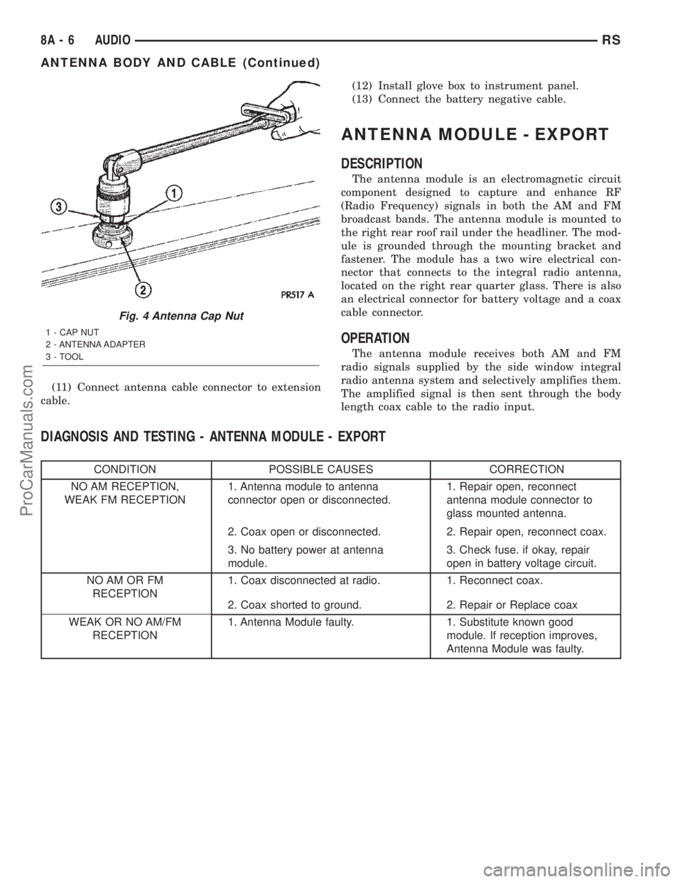
(11) Connect antenna cable connector to extension
cable.(12) Install glove box to instrument panel.
(13) Connect the battery negative cable.
ANTENNA MODULE - EXPORT
DESCRIPTION
The antenna module is an electromagnetic circuit
component designed to capture and enhance RF
(Radio Frequency) signals in both the AM and FM
broadcast bands. The antenna module is mounted to
the right rear roof rail under the headliner. The mod-
ule is grounded through the mounting bracket and
fastener. The module has a two wire electrical con-
nector that connects to the integral radio antenna,
located on the right rear quarter glass. There is also
an electrical connector for battery voltage and a coax
cable connector.
OPERATION
The antenna module receives both AM and FM
radio signals supplied by the side window integral
radio antenna system and selectively amplifies them.
The amplified signal is then sent through the body
length coax cable to the radio input.
DIAGNOSIS AND TESTING - ANTENNA MODULE - EXPORT
CONDITION POSSIBLE CAUSES CORRECTION
NO AM RECEPTION,
WEAK FM RECEPTION1. Antenna module to antenna
connector open or disconnected.1. Repair open, reconnect
antenna module connector to
glass mounted antenna.
2. Coax open or disconnected. 2. Repair open, reconnect coax.
3. No battery power at antenna
module.3. Check fuse. if okay, repair
open in battery voltage circuit.
NO AM OR FM
RECEPTION1. Coax disconnected at radio. 1. Reconnect coax.
2. Coax shorted to ground. 2. Repair or Replace coax
WEAK OR NO AM/FM
RECEPTION1. Antenna Module faulty. 1. Substitute known good
module. If reception improves,
Antenna Module was faulty.
Fig. 4 Antenna Cap Nut
1 - CAP NUT
2 - ANTENNA ADAPTER
3 - TOOL
8A - 6 AUDIORS
ANTENNA BODY AND CABLE (Continued)
ProCarManuals.com
Page 366 of 2399
CLUTCH VOLUME INDEX (CVI)
An important function of the TCM is to monitor
Clutch Volume Index (CVI). CVIs represent the vol-
ume of fluid needed to compress a clutch pack.
The TCM monitors gear ratio changes by monitor-
ing the Input and Output Speed Sensors. The Input,
or Turbine Speed Sensor sends an electrical signal to
the TCM that represents input shaft rpm. The Out-
put Speed Sensor provides the TCM with output
shaft speed information.
By comparing the two inputs, the TCM can deter-
mine transaxle gear ratio. This is important to the
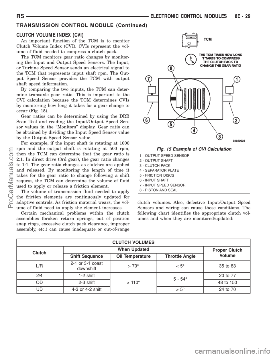
CVI calculation because the TCM determines CVIs
by monitoring how long it takes for a gear change to
occur (Fig. 15).
Gear ratios can be determined by using the DRB
Scan Tool and reading the Input/Output Speed Sen-
sor values in the ªMonitorsº display. Gear ratio can
be obtained by dividing the Input Speed Sensor value
by the Output Speed Sensor value.
For example, if the input shaft is rotating at 1000
rpm and the output shaft is rotating at 500 rpm,
then the TCM can determine that the gear ratio is
2:1. In direct drive (3rd gear), the gear ratio changes
to 1:1. The gear ratio changes as clutches are applied
and released. By monitoring the length of time it
takes for the gear ratio to change following a shift
request, the TCM can determine the volume of fluid
used to apply or release a friction element.
The volume of transmission fluid needed to apply
the friction elements are continuously updated for
adaptive controls. As friction material wears, the vol-
ume of fluid need to apply the element increases.
Certain mechanical problems within the clutch
assemblies (broken return springs, out of position
snap rings, excessive clutch pack clearance, improper
assembly, etc.) can cause inadequate or out-of-rangeclutch volumes. Also, defective Input/Output Speed
Sensors and wiring can cause these conditions. The
following chart identifies the appropriate clutch vol-
umes and when they are monitored/updated:
CLUTCH VOLUMES
ClutchWhen Updated
Proper Clutch
Volume
Shift Sequence Oil Temperature Throttle Angle
L/R2-1 or 3-1 coast
downshift>70É <5É 35to83
2/4 1-2 shift
> 110É5 - 54É20 to 77
OD 2-3 shift 48 to 150
UD 4-3 or 4-2 shift > 5É 24 to 70
Fig. 15 Example of CVI Calculation
1 - OUTPUT SPEED SENSOR
2 - OUTPUT SHAFT
3 - CLUTCH PACK
4 - SEPARATOR PLATE
5 - FRICTION DISCS
6 - INPUT SHAFT
7 - INPUT SPEED SENSOR
8 - PISTON AND SEAL
RSELECTRONIC CONTROL MODULES8E-29
TRANSMISSION CONTROL MODULE (Continued)
ProCarManuals.com
Page 533 of 2399
STANDARD PROCEDURE - COMPASS
DEMAGNETIZING
A degaussing tool (Special Tool 6029) is used to
demagnetize, or degauss, the overhead console for-
ward mounting screw and the roof panel above the
overhead console. Equivalent units must be rated as
continuous duty for 110/115 volts and 60 Hz. They
must also have a field strength of over 350 gauss at 7
millimeters (0.25 inch) beyond the tip of the probe.
To demagnetize the roof panel and the overhead
console forward mounting screw, proceed as follows:
(1) Be certain that the ignition switch is in the Off
position, before you begin the demagnetizing proce-
dure.
(2) Connect the degaussing tool to an electrical
outlet, while keeping the tool at least 61 centimeters
(2 feet) away from the compass unit.
(3) Slowly approach the head of the overhead con-
sole forward mounting screw with the degaussing
tool connected.
(4) Contact the head of the screw with the plastic
coated tip of the degaussing tool for about two sec-
onds.
(5) With the degaussing tool still energized, slowly
back it away from the screw. When the tip of the tool
is at least 61 centimeters (2 feet) from the screw
head, disconnect the tool.
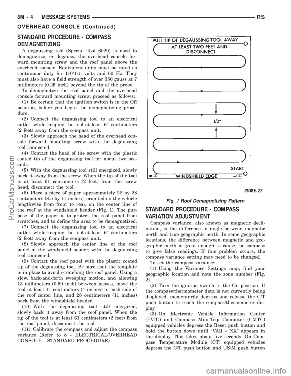
(6) Place a piece of paper approximately 22 by 28
centimeters (8.5 by 11 inches), oriented on the vehicle
lengthwise from front to rear, on the center line of
the roof at the windshield header (Fig. 1). The pur-
pose of the paper is to protect the roof panel from
scratches, and to define the area to be demagnetized.
(7) Connect the degaussing tool to an electrical
outlet, while keeping the tool at least 61 centimeters
(2 feet) away from the compass unit.
(8) Slowly approach the center line of the roof
panel at the windshield header, with the degaussing
tool connected.
(9) Contact the roof panel with the plastic coated
tip of the degaussing tool. Be sure that the template
is in place to avoid scratching the roof panel. Using a
slow, back-and-forth sweeping motion, and allowing
13 millimeters (0.50 inch) between passes, move the
tool at least 11 centimeters (4 inches) to each side of
the roof center line, and 28 centimeters (11 inches)
back from the windshield header.
(10) With the degaussing tool still energized,
slowly back it away from the roof panel. When the
tip of the tool is at least 61 centimeters (2 feet) from
the roof panel, disconnect the tool.
(11) Calibrate the compass and adjust the compass
variance (Refer to 8 - ELECTRICAL/OVERHEAD
CONSOLE - STANDARD PROCEDURE).
STANDARD PROCEDURE - COMPASS
VARIATION ADJUSTMENT
Compass variance, also known as magnetic decli-
nation, is the difference in angle between magnetic
north and true geographic north. In some geographic
locations, the difference between magnetic and geo-
graphic north is great enough to cause the compass
to give false readings. If this problem occurs, the
compass variance setting may need to be changed.
To set the compass variance:
(1) Using the Variance Settings map, find your
geographic location and note the zone number (Fig.
2).
(2) Turn the ignition switch to the On position. If
the compass/thermometer data is not currently being
displayed, momentarily depress and release the C/T
push button to reach the compass/thermometer dis-
play.
(3) On Electronic Vehicle Information Center
(EVIC) and Compass Mini-Trip Computer (CMTC)
equipped vehicles depress the Reset push button and
hold the button down until ªVAR = XXº appears in
the display. This takes about five seconds. On Com-
pass Temperature Module (CT) equipped vehicles
depress the C/T push button and US/M push button
Fig. 1 Roof Demagnetizing Pattern
8M - 4 MESSAGE SYSTEMSRS
OVERHEAD CONSOLE (Continued)
ProCarManuals.com