lumbar support CHRYSLER CARAVAN 2002 Service Manual
[x] Cancel search | Manufacturer: CHRYSLER, Model Year: 2002, Model line: CARAVAN, Model: CHRYSLER CARAVAN 2002Pages: 2399, PDF Size: 57.96 MB
Page 1995 of 2399

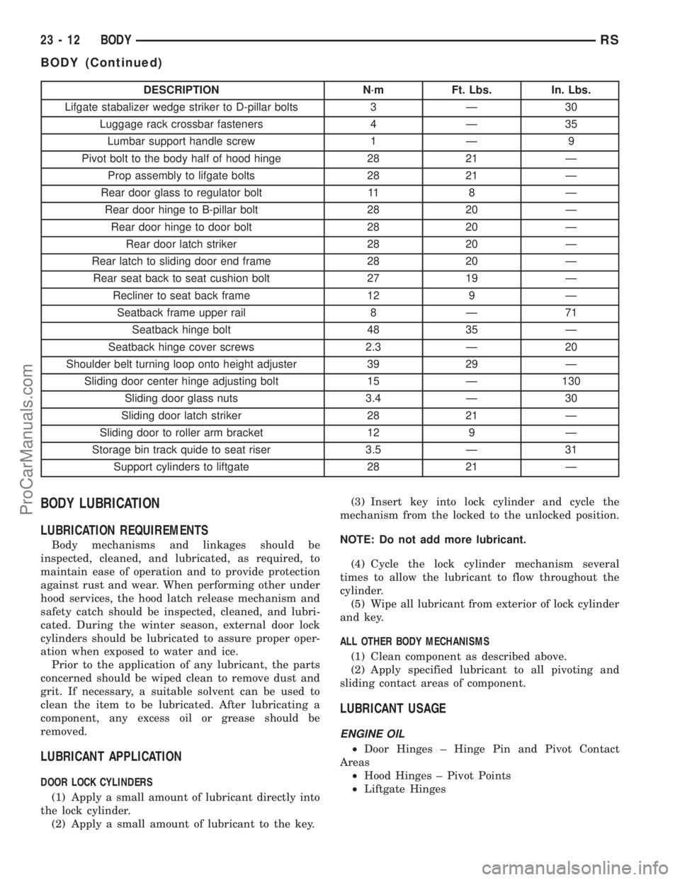
DESCRIPTION N´m Ft. Lbs. In. Lbs.
Lifgate stabalizer wedge striker to D-pillar bolts 3 Ð 30
Luggage rack crossbar fasteners 4 Ð 35
Lumbar support handle screw 1 Ð 9
Pivot bolt to the body half of hood hinge 28 21 Ð
Prop assembly to lifgate bolts 28 21 Ð
Rear door glass to regulator bolt 11 8 Ð
Rear door hinge to B-pillar bolt 28 20 Ð
Rear door hinge to door bolt 28 20 Ð
Rear door latch striker 28 20 Ð
Rear latch to sliding door end frame 28 20 Ð
Rear seat back to seat cushion bolt 27 19 Ð
Recliner to seat back frame 12 9 Ð
Seatback frame upper rail 8 Ð 71
Seatback hinge bolt 48 35 Ð
Seatback hinge cover screws 2.3 Ð 20
Shoulder belt turning loop onto height adjuster 39 29 Ð
Sliding door center hinge adjusting bolt 15 Ð 130
Sliding door glass nuts 3.4 Ð 30
Sliding door latch striker 28 21 Ð
Sliding door to roller arm bracket 12 9 Ð
Storage bin track quide to seat riser 3.5 Ð 31
Support cylinders to liftgate 28 21 Ð
BODY LUBRICATION
LUBRICATION REQUIREMENTS
Body mechanisms and linkages should be
inspected, cleaned, and lubricated, as required, to
maintain ease of operation and to provide protection
against rust and wear. When performing other under
hood services, the hood latch release mechanism and
safety catch should be inspected, cleaned, and lubri-
cated. During the winter season, external door lock
cylinders should be lubricated to assure proper oper-
ation when exposed to water and ice.
Prior to the application of any lubricant, the parts
concerned should be wiped clean to remove dust and
grit. If necessary, a suitable solvent can be used to
clean the item to be lubricated. After lubricating a
component, any excess oil or grease should be
removed.
LUBRICANT APPLICATION
DOOR LOCK CYLINDERS
(1) Apply a small amount of lubricant directly into
the lock cylinder.
(2) Apply a small amount of lubricant to the key.(3) Insert key into lock cylinder and cycle the
mechanism from the locked to the unlocked position.
NOTE: Do not add more lubricant.
(4) Cycle the lock cylinder mechanism several
times to allow the lubricant to flow throughout the
cylinder.
(5) Wipe all lubricant from exterior of lock cylinder
and key.
ALL OTHER BODY MECHANISMS
(1) Clean component as described above.
(2) Apply specified lubricant to all pivoting and
sliding contact areas of component.
LUBRICANT USAGE
ENGINE OIL
²Door Hinges ± Hinge Pin and Pivot Contact
Areas
²Hood Hinges ± Pivot Points
²Liftgate Hinges
23 - 12 BODYRS
BODY (Continued)
ProCarManuals.com
Page 2069 of 2399

BENCH SEAT BACK
REMOVAL............................102
INSTALLATION........................103
BENCH SEAT BACK COVER
REMOVAL............................103
INSTALLATION........................103
BENCH SEAT TRACK
REMOVAL............................103
INSTALLATION........................104
PLASTIC GROCERY BAG RETAINER
REMOVAL............................104
INSTALLATION........................104UNDER SEAT STORAGE BIN
REMOVAL............................104
INSTALLATION........................105
UNDER SEAT STORAGE BIN GUIDE
REMOVAL............................105
INSTALLATION........................105
UNDER SEAT STORAGE BIN LOCK/LATCH
REMOVAL............................105
INSTALLATION........................105
LUMBAR SUPPORT
REMOVAL............................106
INSTALLATION........................106
CHILD SEAT MODULE
REMOVAL
(1) Close child restraint seat.
(2) Remove seat back cover.
(3) Remove screws attaching child restraint seat
module hinges to seat back frame lower rail (Fig. 1).
(4) Return seat back to upright position.
(5) Disengage push in fasteners attaching upper
bolster to child restraint seat module (Fig. 2).
(6) Remove screws attaching top of module to seat
back frame upper rail (Fig. 3).
(7) Remove child restraint seat module from seat
back (Fig. 4).
Fig. 1 CHILD RESTRAINT SEAT LOWER HINGE
1 - CHILD RESTRAINT SEAT MODULE
2 - LOWER HINGE
Fig. 2 CHILD RESTRAINT SEAT UPPER BOLSTER
1 - UPPER BOLSTER
2 - CHILD RESTRAINT SEAT MODULE
3 - PUSH-IN FASTENER
Fig. 3 CHILD RESTRAINT SEAT UPPER SCREWS
1 - UPPER BOLSTER
2 - CHILD RESTRAINT SEAT MODULE
23 - 86 SEATSRS
ProCarManuals.com
Page 2089 of 2399

LUMBAR SUPPORT
REMOVAL
(1) Remove screw attaching lumbar handle to seat
back (Fig. 47).
(2) Remove seat back assembly from cushion.
(3) Detrim the seat back assembly.
(4) Remove frame and replace.
INSTALLATION
(1) Trim the seat back frame.
(2) Install seat back assembly to cushion.
(3) Install attaching screw to lumbar handle. The
handle is to be installed, between two and three
O'clock position. Tighten screw to 1 N´m (11 ft. lbs.)
torque.
(4) Test lumbar operation.
Fig. 47 LUMBAR HANDLE
1 - LUMBAR HANDLE
23 - 106 SEATSRS
ProCarManuals.com