steering CHRYSLER CARAVAN 2003 Service Manual
[x] Cancel search | Manufacturer: CHRYSLER, Model Year: 2003, Model line: CARAVAN, Model: CHRYSLER CARAVAN 2003Pages: 2177, PDF Size: 59.81 MB
Page 402 of 2177

REMOVAL
REMOVAL - 2.4L
The electronic ignition coil pack attaches directly
to the valve cover.
(1) Diconnect the negative battery cable.
(2) Disconnect electrical connector from coil pack
(3) Remove coil pack mounting bolts.
(4) Remove coil pack and heat shield (Fig. 9).
REMOVAL - 3.3/3.8L
(1) Disconnect the negative battery cable.
(2) Remove the throttle and speed control cables
from clip.
(3) Remove 2 bolts from the Power steering reser-
voir to intake manifold.
(4) Loosen the lower nut for the power steering
reservoir from stud on ignition coil bracket.
(5) Reposition the Power steering reservoir (Fig.
11).
(6) Remove the ignition cables from the ignition
coil.
(7) Disconnect the electrical connector from the
ignition coil.
(8) Remove 2 nuts from the ignition coil studs.
(9) Remove 2 bolts from ignition coil, remove coil.
INSTALLATION
INSTALLATION - 2.4L
(1) Install ignition coil and heat shield to valve
cover and tighten bolts.
(2) Connect the electrical connector to the ignition
coil.
(3) Transfer spark plug cables to new coil pack.
The coil pack towers are numbered with the cylinder
identification. Be sure the ignition cables are fully
seated onto the towers.
(4) Connect the negative battery cable.
INSTALLATION - 3.3/3.8L
(1) Install coil over studs on bracket.
(2) Install 2 bolts to ignition coil.
(3) Install 2 nuts to the ignition coil studs. Tighten
nuts and bolts.
(4) Connect the electrical connector to the ignition
coil.
(5) Install the ignition cables to the ignition coil.
(6) Reposition the Power steering reservoir. Slide
bracket over the mounting stud (Fig. 11).
(7) Install 2 bolts to the Power steering reservoir
to intake manifold.
(8) Tighten the lower nut to stud on ignition coil
bracket.
(9) Install the throttle and speed control cables to
clip.
(10) Connect the negative battery cable.
Fig. 10 IGNITION COIL - 3.3/3.8L
1 -Ignition Coil
Fig. 11 IGNITION COIL BRACKET 3.3/3.8L
RSIGNITION CONTROL8I-7
IGNITION COIL (Continued)
ProCarManuals.com
Page 415 of 2177

ELECTRONIC GEAR INDICATOR DISPLAY DIAGNOSIS
CONDITION POSSIBLE CAUSES CORRECTION
NO DISPLAY. 1. INTERNAL CLUSTER
FAILURE.1. PERFORM CLUSTER SELF-DIAGNOSTIC TEST
AND CHECK FOR FAULT CODES.
²IF PRND3L (PRND1234 IF AUTOSTICK
EQUIPPED) PASSES THE SEGMENT CHECK, THEN
FAILURE MAY NOT BE IN THE CLUSTER. LOOK
FOR ANOTHER POSSIBLE CAUSE OF FAILURE. IF
IT FAILS, REPLACE CLUSTER ASSEMBLY.
ERRATIC DISPLAY. 1. INTERNAL CLUSTER
FAILURE.1. PERFORM CLUSTER SELF-DIAGNOSTIC TEST
AND CHECK FOR FAULT CODES.
²IF PRND3L (PRND1234 IF AUTOSTICK
EQUIPPED) PASSES THE SEGMENT CHECK, THEN
FAILURE MAY NOT BE IN THE CLUSTER. LOOK
FOR ANOTHER POSSIBLE CAUSE OF FAILURE.
2. BAD PCI BUS
MESSAGE FROM THE
TCM.2. USE A DRB IIITSCAN TOOL TO CHECK THE
TCM. REFER TO THE PROPER TRANSMISSION
DIAGNOSTIC PROCEDURES MANUAL TO
PROPERLY DIAGNOSE AND REPAIR.
ALL SEGMENTS ARE ON. 1. NO PCI BUS
MESSAGE FROM THE
TCM.1.A. PERFORM CLUSTER SELF-DIAGNOSTIC TEST.
IF PRND3L (PRND1234 IF AUTOSTICK EQUIPPED)
PASSES TEST GO TO STEP 1.B. IF PRND3L
(PRND1234 IF AUTOSTICK EQUIPPED) FAILS TEST,
REPLACE CLUSTER ASSEMBLY.
1.B. CHECK THE TCM USING A DRB IIITSCAN
TOOL. REFER TO THE PROPER TRANSMISSION
DIAGNOSTIC PROCEDURES MANUAL TO
PROPERLY DIAGNOSE AND REPAIR.
REMOVAL
(1) Disconnect and isolate the battery negative
cable.
(2) Remove Over Steering Column Bezel by lifting
it straight up with a firm pull.
(3) Remove the four cluster bezel attaching screws.
(4) Tilt the steering column in the full down posi-
tion.
(5) Pull rearward on the cluster bezel and remove.
(6) Remove the four screws holding instrument
cluster to instrument panel.
(7) Rotate top of cluster outward.
(8) Disconnect the cluster harness connector.
(9) Remove instrument cluster from instrument
panel.
INSTALLATION
(1) Connect the instrument cluster wire connector.
(2) Rotate top of cluster inward as placing into
instrument panel opening.
(3) Install the four screws holding instrument clus-
ter to instrument panel.
(4) Position cluster bezel into place.(5) Install the four bezel attaching screws.
(6) Install the Over Steering Column Bezel by
firmly snapping into place.
(7) Connect the battery negative cable.
CLUSTER LENS
REMOVAL
(1) Remove the instrument cluster. Refer to Elec-
trical, Instrument Cluster, Removal.
(2) Remove the screws holding the lens to the
instrument cluster.
(3) Press down on the snap features of the lens
and remove the lens from the cluster.
INSTALLATION
(1) Insert the lens snap features into the cluster.
(2) Install the screws holding the lens to the
instrument cluster.
(3) Install the instrument cluster. Refer to Electri-
cal, Instrument Cluster, Installation.
8J - 10 INSTRUMENT CLUSTERRS
INSTRUMENT CLUSTER (Continued)
ProCarManuals.com
Page 420 of 2177
locked) and cannot be readjusted or released
even if the lever is moved back.
DIAGNOSIS AND TESTING - BRAKE LAMP
SWITCH
NOTE: Before proceeding with this diagnostic test,
verify the adjustment lever on the back of the
switch is in the adjusted position. If the lever is in
the non-adjusted (diagonal) position it may have
never been adjusted (Refer to 8 - ELECTRICAL/
LAMPS/LIGHTING - EXTERIOR/BRAKE LAMP
SWITCH - OPERATION). For adjustment, (Refer to 8
- ELECTRICAL/LAMPS/LIGHTING - EXTERIOR/
BRAKE LAMP SWITCH - INSTALLATION)
If the electrical circuit has been tested and the
brake lamp switch is suspected of being faulty, it can
be tested using the following method.
(1) Remove the switch from the vehicle. (Refer to 8
- ELECTRICAL/LAMPS/LIGHTING - EXTERIOR/
BRAKE LAMP SWITCH - REMOVAL)
(2) With the switch in the released position (plung-
er extended), use an ohmmeter to test each of the
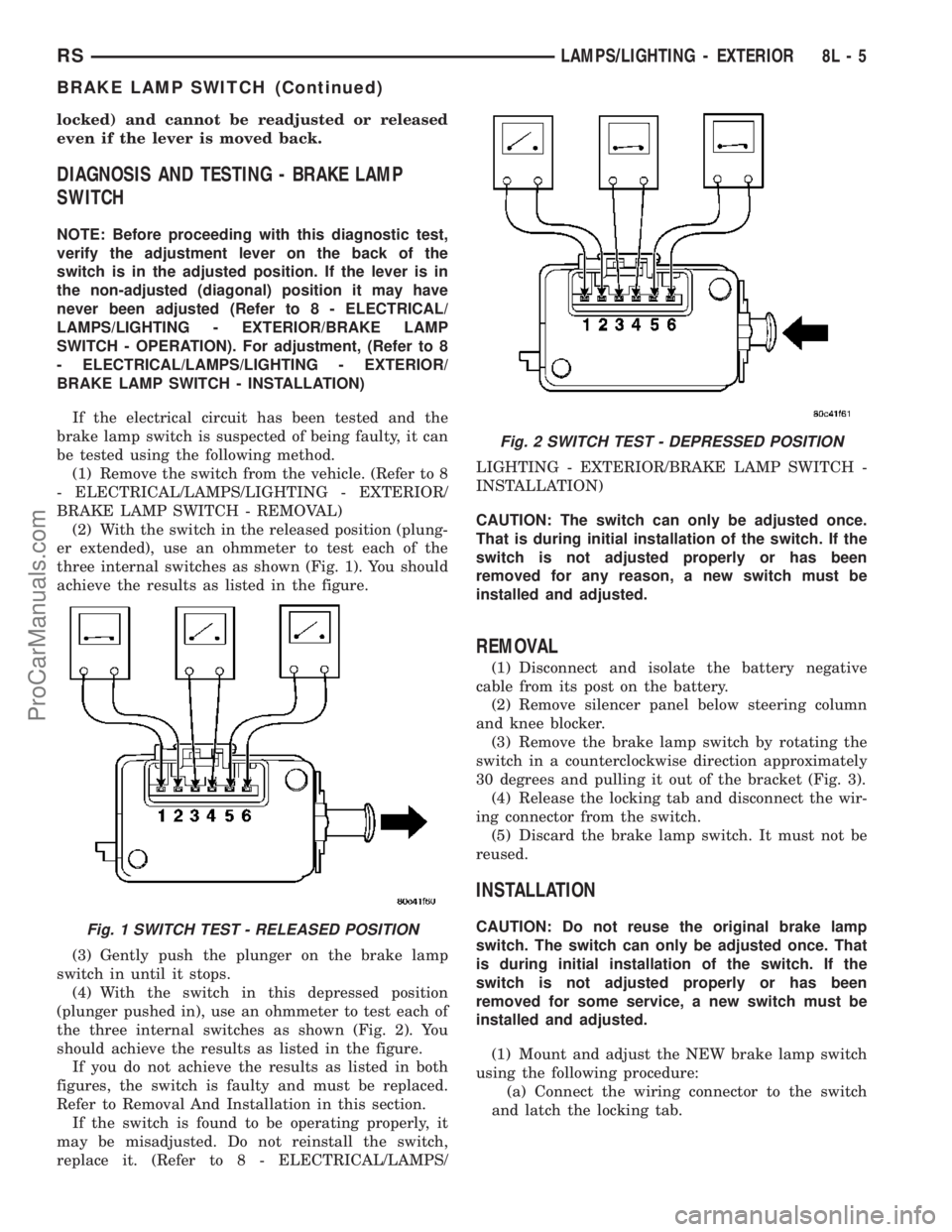
three internal switches as shown (Fig. 1). You should
achieve the results as listed in the figure.
(3) Gently push the plunger on the brake lamp
switch in until it stops.
(4) With the switch in this depressed position
(plunger pushed in), use an ohmmeter to test each of
the three internal switches as shown (Fig. 2). You
should achieve the results as listed in the figure.
If you do not achieve the results as listed in both
figures, the switch is faulty and must be replaced.
Refer to Removal And Installation in this section.
If the switch is found to be operating properly, it
may be misadjusted. Do not reinstall the switch,
replace it. (Refer to 8 - ELECTRICAL/LAMPS/LIGHTING - EXTERIOR/BRAKE LAMP SWITCH -
INSTALLATION)
CAUTION: The switch can only be adjusted once.
That is during initial installation of the switch. If the
switch is not adjusted properly or has been
removed for any reason, a new switch must be
installed and adjusted.
REMOVAL
(1) Disconnect and isolate the battery negative
cable from its post on the battery.
(2) Remove silencer panel below steering column
and knee blocker.
(3) Remove the brake lamp switch by rotating the
switch in a counterclockwise direction approximately
30 degrees and pulling it out of the bracket (Fig. 3).
(4) Release the locking tab and disconnect the wir-
ing connector from the switch.
(5) Discard the brake lamp switch. It must not be
reused.
INSTALLATION
CAUTION: Do not reuse the original brake lamp
switch. The switch can only be adjusted once. That
is during initial installation of the switch. If the
switch is not adjusted properly or has been
removed for some service, a new switch must be
installed and adjusted.
(1) Mount and adjust the NEW brake lamp switch
using the following procedure:
(a) Connect the wiring connector to the switch
and latch the locking tab.Fig. 1 SWITCH TEST - RELEASED POSITION
Fig. 2 SWITCH TEST - DEPRESSED POSITION
RSLAMPS/LIGHTING - EXTERIOR8L-5
BRAKE LAMP SWITCH (Continued)
ProCarManuals.com
Page 421 of 2177

(b) Install the switch in its bracket by aligning
the index tab on the switch with the slot in the
mounting bracket.
(c) When the switch is fully seated in its
bracket, rotate the switch clockwise approximately
30É to lock the switch into place.
(d) With the brake pedal in the fully released
position, move the lever on the back of the brake
lamp switch from the angled non-adjusted position
to the full vertical position as shown (Fig. 4). This
will adjust the brake lamp switch to the vehicle.(2) Install silencer panel below steering column
knee blocker.
(3) Reconnect the battery negative terminal.
(4) Check the stop lamps to verify they are operat-
ing properly and not staying on when the pedal is in
the released position.
(5) Road test the vehicle to ensure proper opera-
tion of the brakes including ABS and speed control (if
equipped).
CENTER HIGH MOUNTED
STOP LAMP
REMOVAL
(1) Disconnect and isolate the battery negative
cable.
(2) Remove two retaining screws (Fig. 5).
(3) Twist socket counter-clockwise and remove
from lamp.
(4) Pull bulb from socket (Fig. 7).
INSTALLATION
(1) Push bulb into socket.
(2) Install socket into the lamp unit.
(3) Install the retaining screws.
(4) Reconnect the battery negative cable.
CENTER HIGH MOUNTED
STOP LAMP UNIT
REMOVAL
(1) Disconnect and isolate the battery negative
cable.
(2) Remove the two retaining screws (Fig. 5).
(3) Disconnect the rear window washer nozzle
assembly (Fig. 6).
Fig. 3 Brake Lamp Switch And Pedal With Bracket
1 - BRAKE LAMP SWITCH
2 - WIRING CONNECTOR
3 - PEDAL AND BRACKET
Fig. 4 Adjustment Lever Movement
Fig. 5 CHMSL UNIT
1 - CHMSL UNIT
2 - LIFTGATE
8L - 6 LAMPS/LIGHTING - EXTERIORRS
BRAKE LAMP SWITCH (Continued)
ProCarManuals.com
Page 432 of 2177
HEADLAMP
SWITCH
POSITION13-WAY
CONNECTOR
TERMINALRESISTANCE
HEADLAMP
LEVELING
SWITCH
POSITION13-WAY
CONNECTOR
TERMINALRESISTANCE
01 TO 7 3238 - 3456V
1 TO 2 3181 - 3400V
1 1 TO 7 1195 - 1225V
2 1 TO 7 746 - 765V
REMOVAL
(1) Disconnect and isolate the battery negative
cable.
(2) Remove the Instrument Panel Lower Steering
Column Cover. Refer to Body, Instrument Panel,
Lower Steering Column Cover, Removal.
(3) Reach up behind the left side of the instrument
panel and depress spring clip on top or bottom of
headlamp switch. Firmly push out on the headlamp
switch assembly.
(4) Disconnect the wiring connectors.
(5) Remove switch from vehicle.
INSTALLATION
(1) Connect the wiring connectors.
(2) Place headlamp switch assembly into position
and firmly snap into place.
(3) Install the Instrument Panel Lower Steering
Column Cover. Refer to Body, Instrument Panel,
Lower Steering Column Cover, Installation.
(4) Connect the battery negative cable.
HEADLAMP UNIT
STANDARD PROCEDURE
STANDARD PROCEDURE - HEADLAMP UNIT
ALIGNMENT
HEADLAMP UNIT ALIGNMENT PREPARATION
(1) Verify headlamp dimmer switch and high beam
indicator operation.
(2) Inspect and correct damaged or defective com-
ponents that could interfere with proper headlamp
alignment.
(3) Verify proper tire inflation.
(4) Clean headlamp lenses.
(5) Verify that luggage area is loaded as the vehi-
cle is routinely used.(6) Vehicles equipped with automatic load leveling
suspension should be driven normally for approxi-
mately 5 km (3 miles) before attempting a proper
headlamp unit alignment.
(7) Fuel tank should be FULL. Add 2.94 kg (6.5
lbs.) of weight over the fuel tank for each estimated
gallon of missing fuel.
ALIGNMENT SCREEN PREPARATION
(1) Position vehicle on a level surface perpendicu-
lar to a flat wall 7.62 meters (25 ft.) away from front
of headlamp lens (Fig. 19).
(2) If necessary, tape a line on the floor 7.62
meters (25 ft.) away from and parallel to the wall.
(3) Rock vehicle side-to-side three times and allow
suspension to stabilize.
(4) Jounce front suspension three times by pushing
downward on front bumper and releasing.
(5) Measure the distance from the center of head-
lamp lens to the floor. Transfer measurement to the
alignment screen (with tape). Use this line for
up/down adjustment reference.
HEADLAMP UNIT ADJUSTMENT
The low beam headlamp will project on the screen
upper edge of the beam (cut-off) at the horizontal
lamp centerline 50 mm (2 in.). Horizontal aim is
preset and can not be adjusted. The high beam pat-
tern should be correct when the low beams are
aligned properly (Fig. 20). To adjust headlamp verti-
cal alignment, rotate adjustment screw to achieve the
specified low beam cut-off location.
STANDARD PROCEDURE - HEADLAMP UNIT
ALIGNMENT - EXPORT
HEADLAMP UNIT ALIGNMENT PREPARATION
(1) Verify that the headlamp leveling switch is in
the ª0º position.
(2) Inspect and correct damaged or defective com-
ponents that could interfere with proper headlamp
alignment.
(3) Verify proper tire inflation.
(4) Clean headlamp lenses.
(5) Verify that luggage area is loaded as the vehi-
cle is routinely used.
(6) Vehicles equipped with automatic load leveling
suspension should be driven normally for approxi-
mately 5 km (3 miles) before attempting a proper
headlamp unit alignment.
(7) Fuel tank should be FULL. Add 2.94 kg (6.5
lbs.) of weight over the fuel tank for each estimated
gallon of missing fuel.
RSLAMPS/LIGHTING - EXTERIOR8L-17
HEADLAMP SWITCH (Continued)
ProCarManuals.com
Page 436 of 2177
MULTI-FUNCTION SWITCH
DESCRIPTION - TURN SIGNAL SYSTEM
The turn signals are actuated with a lever on
Multi-Function Switch, located on the left side of the
steering wheel. The signals are automatically turned
off by a canceling cam (two lobes molded to the clock
spring mechanism). The cam comes in contact with
the cancel actuator on the turn signal (multi-func-
tion) switch assembly. Either cam lobe, pushing on
the cancel actuator, returns the switch to the OFF
position. The multi-function switch is a resistive
MUX switch that feeds inputs to the BCM.
OPERATION - TURN SIGNAL SYSTEM
Lane change signaling is actuated by applying par-
tial turn signal stalk movement toward the direction
desired until the indicator lamps flashes in the
instrument cluster. When the switch stalk is released
the stalk will spring back into the neutral position
turning OFF the turn signal.
With the ignition switch ON and the turn signal
switch stalk actuated left or right, current flows
through the:
²Multi-function switch
²Body Control Module
²Integrated Power Module (IPM)
²Turn indicator lamp
²Front and rear turn signal bulbs.
A chime will sound after the vehicle has traveled a
distance of approximately 1.0 mile and a speed of 15
mph, with the turn signal ON.
DIAGNOSIS AND TESTING - MULTI-FUNCTION
SWITCH
To test turn signal, headlamp beam select and opti-
cal horn portion of the multi-function switch:(1) Remove the multi-function switch, refer to
Electrical, Lamps/Lighting - Exterior, Multi-Function
Switch, Removal, and Installation.
(2) Using an ohmmeter check the resistance read-
ings between multi-function switch pins. Refer to
Wiring Diagrams for proper pin numbers and the
MULTI-FUNCTION SWITCH RESISTANCE table.
MULTI-FUNCTION SWITCH RESISTANCE
SWITCH
POSITIONPIN NUMBER RESISTANCE
LEFT 2 AND 3 2.7V 5%
RIGHT 2 AND 3 1KV 5%
OPTICAL
HORN2 AND 4 1.7KV 5%
HI BEAM 2 AND 4 2.32KV 5%
REMOVAL
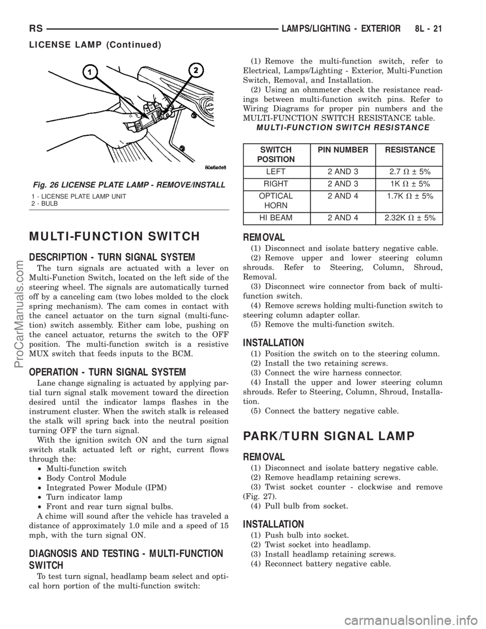
(1) Disconnect and isolate battery negative cable.
(2) Remove upper and lower steering column
shrouds. Refer to Steering, Column, Shroud,
Removal.
(3) Disconnect wire connector from back of multi-
function switch.
(4) Remove screws holding multi-function switch to
steering column adapter collar.
(5) Remove the multi-function switch.
INSTALLATION
(1) Position the switch on to the steering column.
(2) Install the two retaining screws.
(3) Connect the wire harness connector.
(4) Install the upper and lower steering column
shrouds. Refer to Steering, Column, Shroud, Installa-
tion.
(5) Connect the battery negative cable.
PARK/TURN SIGNAL LAMP
REMOVAL
(1) Disconnect and isolate battery negative cable.
(2) Remove headlamp retaining screws.
(3) Twist socket counter - clockwise and remove
(Fig. 27).
(4) Pull bulb from socket.
INSTALLATION
(1) Push bulb into socket.
(2) Twist socket into headlamp.
(3) Install headlamp retaining screws.
(4) Reconnect battery negative cable.
Fig. 26 LICENSE PLATE LAMP - REMOVE/INSTALL
1 - LICENSE PLATE LAMP UNIT
2 - BULB
RSLAMPS/LIGHTING - EXTERIOR8L-21
LICENSE LAMP (Continued)
ProCarManuals.com
Page 503 of 2177
ered. This defeats the day-detect logic. If OK, go to
Step 8. If not OK, replace the faulty mirror unit.
(8) With the mirror darkened, place the transmis-
sion gear selector lever in the Reverse position. The
automatic day/night mirror should return to its nor-
mal reflectance. If not OK, replace the faulty mirror
unit.
Bench testing both mirrors can be done, of care is
exercised. For an inside mirror, the pin closest to he
mount is 12V (+), the next is 12V (-). The third is
reverse override. The fourth is outside mirror (+),
and the fifth is outside mirror (-).Do not apply 12
volts to the fourth and fifth pins.With 12 volts
on pins 1 and 2, the mirror can be tested by blocking
the rear sensor and shining a light into the forward
sensor. For an outside mirror, there is a 2±pin con-
nector. Applying 1.2 volts will cause the mirror to
dim. If the mirror does not dim, the entire glass
assembly can be replaced just as it is when the glass
is broken.
WARNING: Do not apply 12 volts to the outside mir-
ror. Damage to the mirror will result.
POWER FOLDAWAY MIRROR
SWITCH - EXPORT
DESCRIPTION
These vehicles may be equipped with Power Fold-
away Mirrors. This feature allows both the driver
and passenger side view mirrors to fold inward
(retract) on demand. The vehicle has an additional
switch located on the steering column that controls
the folding function of the mirror assembly (Fig. 2).
The fold-away side view mirror is attached to the
vehicle's door in the same manner as mirrors without
the fold-away option. The fold-away mirrors unique
option is the internal motor which allows the mirrors
to fold inward on demand. The fold-away mirror
motor is not serviceable separately and if a motor is
found to be faulty the entire side view mirror must
be replaced.
OPERATION
When the mirror retract switch is depressed, both
of the side view mirrors will fold inward, Thus mak-
ing the overall width of the vehicle the smallest pos-
sible. This can be helpful were parking space is a
absolute minimum.
When the driver's door is opened, only the driver's
door mirror will unfold. If the passenger door is
opened, both mirrors will unfold.
The power fold away mirror system consists of the
following components: mirror switch, side view mir-ror, relay, wires and fuse. Refer to the appropriate
wiring information. The wiring information includes
wiring diagrams, proper wire and connector repair
procedures, details of wire harness routing and
retention, connector pin-out information and location
views for the various wire harness connectors, splices
and grounds.
REMOVAL
(1) Disconnect and isolate the battery negative
cable.
(2) Remove the upper and lower steering column
shroud (Refer to 19 - STEERING/COLUMN/LOWER
SHROUD - REMOVAL).
(3) Disconnect electrical harness connector.
(4) Remove switch from steering column shroud
(Fig. 3).
Fig. 2 POWER FOLDAWAY MIRROR SWITCH
1 - POWER FOLDAWAY MIRROR SWITCH
2 - STEERING COLUMN
Fig. 3 POWER FOLDING MIRROR SWITCH
1 - STEERING COLUMN SHROUD
2 - POWER FOLDAWAY SWITCH
8N - 48 POWER MIRRORSRS
AUTOMATIC DAY / NIGHT MIRROR (Continued)
ProCarManuals.com
Page 504 of 2177
INSTALLATION
(1) Install switch to steering column shroud.
(2) Connect wire harness connector.
(3) Install the upper and lower steering column
shroud (Refer to 19 - STEERING/COLUMN/LOWER
SHROUD - INSTALLATION).
(4) Connect the battery negative cable.
REMOTE SWITCH
DIAGNOSIS AND TESTING - REMOTE SWITCH
(1) Remove power mirror switch. (Refer to 8 -
ELECTRICAL/POWER MIRRORS/POWER MIRROR
SWITCH - REMOVAL).
(2) Disconnect wiring harness at switch connector.
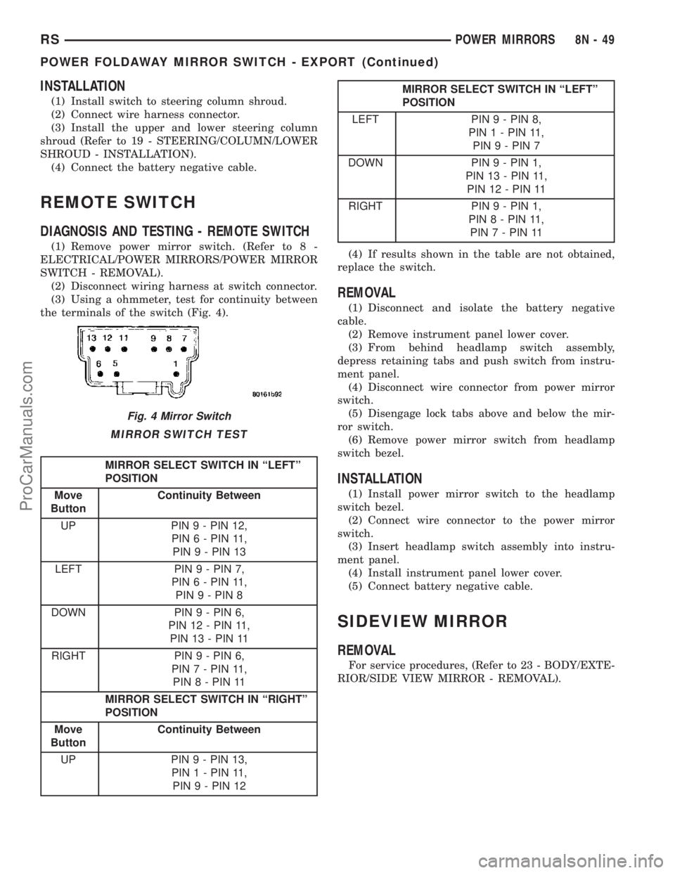
(3) Using a ohmmeter, test for continuity between
the terminals of the switch (Fig. 4).
MIRROR SWITCH TEST
MIRROR SELECT SWITCH IN ªLEFTº
POSITION
Move
ButtonContinuity Between
UP PIN 9 - PIN 12,
PIN 6 - PIN 11,
PIN 9 - PIN 13
LEFT PIN 9 - PIN 7,
PIN 6 - PIN 11,
PIN 9 - PIN 8
DOWN PIN 9 - PIN 6,
PIN 12 - PIN 11,
PIN 13 - PIN 11
RIGHT PIN 9 - PIN 6,
PIN 7 - PIN 11,
PIN 8 - PIN 11
MIRROR SELECT SWITCH IN ªRIGHTº
POSITION
Move
ButtonContinuity Between
UP PIN 9 - PIN 13,
PIN 1 - PIN 11,
PIN 9 - PIN 12
MIRROR SELECT SWITCH IN ªLEFTº
POSITION
LEFT PIN 9 - PIN 8,
PIN 1 - PIN 11,
PIN 9 - PIN 7
DOWN PIN 9 - PIN 1,
PIN 13 - PIN 11,
PIN 12 - PIN 11
RIGHT PIN 9 - PIN 1,
PIN 8 - PIN 11,
PIN 7 - PIN 11
(4) If results shown in the table are not obtained,
replace the switch.
REMOVAL
(1) Disconnect and isolate the battery negative
cable.
(2) Remove instrument panel lower cover.
(3) From behind headlamp switch assembly,
depress retaining tabs and push switch from instru-
ment panel.
(4) Disconnect wire connector from power mirror
switch.
(5) Disengage lock tabs above and below the mir-
ror switch.
(6) Remove power mirror switch from headlamp
switch bezel.
INSTALLATION
(1) Install power mirror switch to the headlamp
switch bezel.
(2) Connect wire connector to the power mirror
switch.
(3) Insert headlamp switch assembly into instru-
ment panel.
(4) Install instrument panel lower cover.
(5) Connect battery negative cable.
SIDEVIEW MIRROR
REMOVAL
For service procedures, (Refer to 23 - BODY/EXTE-
RIOR/SIDE VIEW MIRROR - REMOVAL).
Fig. 4 Mirror Switch
RSPOWER MIRRORS8N-49
POWER FOLDAWAY MIRROR SWITCH - EXPORT (Continued)
ProCarManuals.com
Page 524 of 2177
tion. To test the airbag warning lamp (bulb) opera-
tion in the cluster, refer to Electrical, Instrument
Cluster, Diagnosis and Testing - Instrument Cluster.
Refer to the proper Body Diagnostic Procedures man-
ual for any other system problems.
STANDARD PROCEDURE
STANDARD PROCEDURE - HANDLING
AIRBAGS
DEPLOYED AIRBAG
The vehicle interior may contain a very small
amount of sodium hydroxide powder, a by-product of
airbag deployment. Sodium hydroxide powder can
irritate the skin, eyes, nose and throat. Wear safety
glasses, rubber gloves, and long sleeved clothing
when cleaning any of the powder residue from the
vehicle.
If you find that the cleanup is irritating your skin,
run cool water over the affected area. Also, if you
experience nasal or throat irritation, exit the vehicle
for fresh air until the irritation ceases. If irritation
continues, see a physician.
UNDEPLOYED AIRBAG
The airbags must be stored in its original special
container until used for service. At no time should a
source of electricity be permitted near the inflator on
the back of an airbag module. When carrying or han-
dling an undeployed airbag module, the trim side of
the airbag should be pointing away from the body to
minimize possibility of injury if accidental deploy-
ment occurs. Do not place undeployed airbag face
down on a solid surface, the airbag will propel into
the air if accidental deployment occurs.
STANDARD PROCEDURE - SERVICE AFTER AN
AIRBAG DEPLOYMENT
DRIVER AIRBAG
After a Driver Airbag has been deployed due to a
collision, the followingMUSTbe replaced:
²Driver Airbag
²Clock Spring Assembly
²Steering Wheel
²Complete Steering Column Assembly w/Lower
Steering Column Coupler
All other airbag and vehicle components should be
closely inspected following any airbag deployment,
and should be replaced when visible damage is
incurred.
PASSENGER AIRBAG
After a Passenger Airbag has been deployed due to
a collision. the followingMUSTbe replaced:
²Passenger Airbag
²Instrument Panel and Pad Assembly
All other airbag and vehicle components should be
closely inspected following any airbag deployment,
and should be replaced when visible damage is
incurred.
SEAT AIRBAG
After a Seat Airbag has been deployed due to a col-
lision. the followingMUSTbe replaced:
²Complete Seat Back Assembly
All other airbag and vehicle components should be
closely inspected following any airbag deployment,
and should be replaced when visible damage is
incurred.
SEAT BELT TENSIONERS
After a frontal impact where an airbag has been
deployed due to a collision. the followingMUSTbe
replaced:
²Front Seat Belt Buckle (driver and passenger)
with integral Tensioners.
All other seat belts should be closely inspected for
cuts, tears, fraying, or damage in any way following
any frontal impact or airbag deployment. The other
seat belts are to be replaced when visible damage is
incurred.
CLEAN UP PROCEDURE
Roll or fold the airbag towards its mounting point
(i.e. instrument panel, steering wheel, or seat back).
Then tape the ripped cover over the deployed airbag
if applicable.
Use a vacuum cleaner to remove any residual pow-
der from the vehicle interior. Work from the outside
in to avoid kneeling or sitting in a contaminated
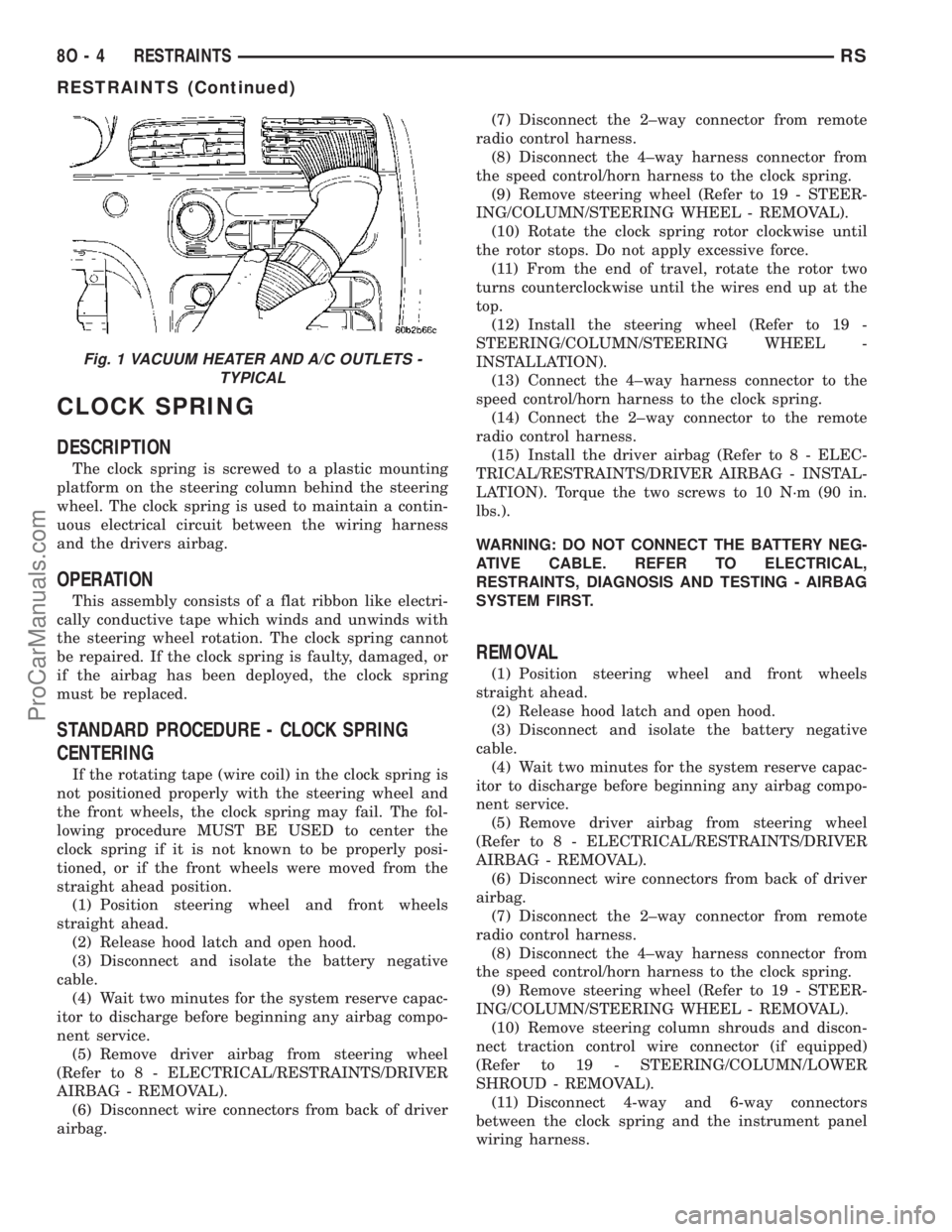
area. Vacuum the heater and A/C outlets as well (Fig.
1). If the heater or air conditioner was in RECIRC
mode at time of airbag deployment, operate blower
motor on low speed and vacuum powder residue
expelled from the heater and A/C outlets. Multiple
vacuum cleaning may be necessary to decontaminate
the interior of the vehicle.
RSRESTRAINTS8O-3
RESTRAINTS (Continued)
ProCarManuals.com
Page 525 of 2177
CLOCK SPRING
DESCRIPTION
The clock spring is screwed to a plastic mounting
platform on the steering column behind the steering
wheel. The clock spring is used to maintain a contin-
uous electrical circuit between the wiring harness
and the drivers airbag.
OPERATION
This assembly consists of a flat ribbon like electri-
cally conductive tape which winds and unwinds with
the steering wheel rotation. The clock spring cannot
be repaired. If the clock spring is faulty, damaged, or
if the airbag has been deployed, the clock spring
must be replaced.
STANDARD PROCEDURE - CLOCK SPRING
CENTERING
If the rotating tape (wire coil) in the clock spring is
not positioned properly with the steering wheel and
the front wheels, the clock spring may fail. The fol-
lowing procedure MUST BE USED to center the
clock spring if it is not known to be properly posi-
tioned, or if the front wheels were moved from the
straight ahead position.
(1) Position steering wheel and front wheels
straight ahead.
(2) Release hood latch and open hood.
(3) Disconnect and isolate the battery negative
cable.
(4) Wait two minutes for the system reserve capac-
itor to discharge before beginning any airbag compo-
nent service.
(5) Remove driver airbag from steering wheel
(Refer to 8 - ELECTRICAL/RESTRAINTS/DRIVER
AIRBAG - REMOVAL).
(6) Disconnect wire connectors from back of driver
airbag.(7) Disconnect the 2±way connector from remote
radio control harness.
(8) Disconnect the 4±way harness connector from
the speed control/horn harness to the clock spring.
(9) Remove steering wheel (Refer to 19 - STEER-
ING/COLUMN/STEERING WHEEL - REMOVAL).
(10) Rotate the clock spring rotor clockwise until
the rotor stops. Do not apply excessive force.
(11) From the end of travel, rotate the rotor two
turns counterclockwise until the wires end up at the
top.
(12) Install the steering wheel (Refer to 19 -
STEERING/COLUMN/STEERING WHEEL -
INSTALLATION).
(13) Connect the 4±way harness connector to the
speed control/horn harness to the clock spring.
(14) Connect the 2±way connector to the remote
radio control harness.
(15) Install the driver airbag (Refer to 8 - ELEC-
TRICAL/RESTRAINTS/DRIVER AIRBAG - INSTAL-
LATION). Torque the two screws to 10 N´m (90 in.
lbs.).
WARNING: DO NOT CONNECT THE BATTERY NEG-
ATIVE CABLE. REFER TO ELECTRICAL,
RESTRAINTS, DIAGNOSIS AND TESTING - AIRBAG
SYSTEM FIRST.
REMOVAL
(1) Position steering wheel and front wheels
straight ahead.
(2) Release hood latch and open hood.
(3) Disconnect and isolate the battery negative
cable.
(4) Wait two minutes for the system reserve capac-
itor to discharge before beginning any airbag compo-
nent service.
(5) Remove driver airbag from steering wheel
(Refer to 8 - ELECTRICAL/RESTRAINTS/DRIVER
AIRBAG - REMOVAL).
(6) Disconnect wire connectors from back of driver
airbag.
(7) Disconnect the 2±way connector from remote
radio control harness.
(8) Disconnect the 4±way harness connector from
the speed control/horn harness to the clock spring.
(9) Remove steering wheel (Refer to 19 - STEER-
ING/COLUMN/STEERING WHEEL - REMOVAL).
(10) Remove steering column shrouds and discon-
nect traction control wire connector (if equipped)
(Refer to 19 - STEERING/COLUMN/LOWER
SHROUD - REMOVAL).
(11) Disconnect 4-way and 6-way connectors
between the clock spring and the instrument panel
wiring harness.
Fig. 1 VACUUM HEATER AND A/C OUTLETS -
TYPICAL
8O - 4 RESTRAINTSRS
RESTRAINTS (Continued)
ProCarManuals.com