check engine CHRYSLER CARAVAN 2003 Service Manual
[x] Cancel search | Manufacturer: CHRYSLER, Model Year: 2003, Model line: CARAVAN, Model: CHRYSLER CARAVAN 2003Pages: 2177, PDF Size: 59.81 MB
Page 1569 of 2177

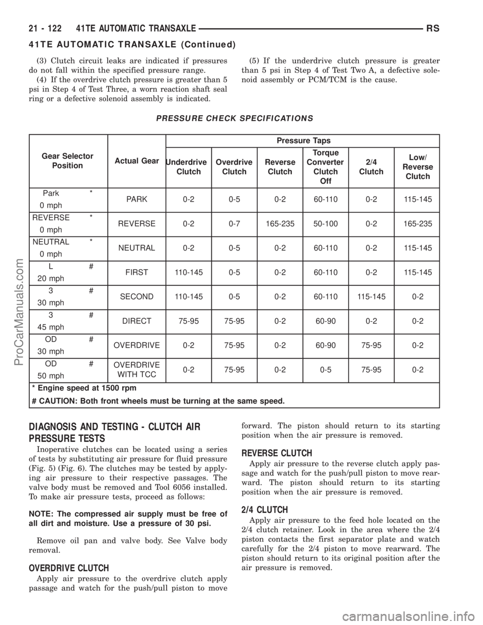
(3) Clutch circuit leaks are indicated if pressures
do not fall within the specified pressure range.
(4)
If the overdrive clutch pressure is greater than 5
psi in Step 4 of Test Three, a worn reaction shaft seal
ring or a defective solenoid assembly is indicated.
(5) If the underdrive clutch pressure is greater
than 5 psi in Step 4 of Test Two A, a defective sole-
noid assembly or PCM/TCM is the cause.
PRESSURE CHECK SPECIFICATIONS
Gear Selector
PositionActual GearPressure Taps
Underdrive
ClutchOverdrive
ClutchReverse
ClutchTorque
Converter
Clutch
Off2/4
ClutchLow/
Reverse
Clutch
Park *
PARK 0-2 0-5 0-2 60-110 0-2 115-145
0 mph
REVERSE *
REVERSE 0-2 0-7 165-235 50-100 0-2 165-235
0 mph
NEUTRAL *
NEUTRAL 0-2 0-5 0-2 60-110 0-2 115-145
0 mph
L#
FIRST 110-145 0-5 0-2 60-110 0-2 115-145
20 mph
3#
SECOND 110-145 0-5 0-2 60-110 115-145 0-2
30 mph
3#
DIRECT 75-95 75-95 0-2 60-90 0-2 0-2
45 mph
OD #
OVERDRIVE 0-2 75-95 0-2 60-90 75-95 0-2
30 mph
OD #
OVERDRIVE
WITH TCC0-2 75-95 0-2 0-5 75-95 0-2
50 mph
* Engine speed at 1500 rpm
# CAUTION: Both front wheels must be turning at the same speed.
DIAGNOSIS AND TESTING - CLUTCH AIR
PRESSURE TESTS
Inoperative clutches can be located using a series
of tests by substituting air pressure for fluid pressure
(Fig. 5) (Fig. 6). The clutches may be tested by apply-
ing air pressure to their respective passages. The
valve body must be removed and Tool 6056 installed.
To make air pressure tests, proceed as follows:
NOTE: The compressed air supply must be free of
all dirt and moisture. Use a pressure of 30 psi.
Remove oil pan and valve body. See Valve body
removal.
OVERDRIVE CLUTCH
Apply air pressure to the overdrive clutch apply
passage and watch for the push/pull piston to moveforward. The piston should return to its starting
position when the air pressure is removed.
REVERSE CLUTCH
Apply air pressure to the reverse clutch apply pas-
sage and watch for the push/pull piston to move rear-
ward. The piston should return to its starting
position when the air pressure is removed.
2/4 CLUTCH
Apply air pressure to the feed hole located on the
2/4 clutch retainer. Look in the area where the 2/4
piston contacts the first separator plate and watch
carefully for the 2/4 piston to move rearward. The
piston should return to its original position after the
air pressure is removed.
21 - 122 41TE AUTOMATIC TRANSAXLERS
41TE AUTOMATIC TRANSAXLE (Continued)
ProCarManuals.com
Page 1570 of 2177

LOW/REVERSE CLUTCH
Apply air pressure to the low/reverse clutch feed
hole (rear of case, between 2 bolt holes). Then, look
in the area where the low/reverse piston contacts the
first separator plate. Watch carefully for the piston to
move forward. The piston should return to its origi-
nal position after the air pressure is removed.
UNDERDRIVE CLUTCH
Because this clutch piston cannot be seen, its oper-
ation is checked by function. Air pressure is applied
to the low/reverse and the 2/4 clutches. This locks the
output shaft. Use a piece of rubber hose wrapped
around the input shaft and a pair of clamp-on pliers
to turn the input shaft. Next apply air pressure to
the underdrive clutch. The input shaft should notrotate with hand torque. Release the air pressure
and confirm that the input shaft will rotate.
DIAGNOSIS AND TESTING - TORQUE
CONVERTER HOUSING FLUID LEAKAGE
When diagnosing converter housing fluid leaks,
three actions must be taken before repair:
(1) Verify proper transmission fluid level.
(2) Verify that the leak originates from the con-
verter housing area and is transmission fluid.
(3) Determine the true source of the leak.
Fluid leakage at or around the torque converter
area may originate from an engine oil leak (Fig. 7).
The area should be examined closely. Factory fill
fluid is red and, therefore, can be distinguished from
engine oil.
Some suspected converter housing fluid leaks may
not be leaks at all. They may only be the result of
residual fluid in the converter housing, or excess
fluid spilled during factory fill, or fill after repair.
Converter housing leaks have several potential
sources. Through careful observation, a leak source
can be identified before removing the transmission
for repair.
Pump seal leaks tend to move along the drive hub
and onto the rear of the converter (Fig. 7). Pump
o-ring or pump body leaks follow the same path as a
seal leak. Pump attaching bolt leaks are generally
deposited on the inside of the converter housing and
not on the converter itself. Pump seal or gasket leaks
usually travel down the inside of the converter hous-
ing (Fig. 7).
Fig. 5 Air Pressure Test Plate
1 - TOOL 6056
2 - ACCUMULATORS
Fig. 6 Testing Reverse Clutch
1 - TOOL 6056
2 - AIR NOZZLE
Fig. 7 Converter Housing Leak Paths
1 - PUMP SEAL
2 - PUMP VENT
3 - PUMP BOLT
4 - PUMP GASKET
5 - CONVERTER HOUSING
6 - CONVERTER
7 - REAR MAIN SEAL LEAK
RS41TE AUTOMATIC TRANSAXLE21 - 123
41TE AUTOMATIC TRANSAXLE (Continued)
ProCarManuals.com
Page 1648 of 2177

PRELOAD ADJUSTMENT W/O SHIM
(1) Remove the bearing cup from the differential
bearing retainer using Miller special Tool 6062A.
(2) Remove existing shim from under bearing cup.
(3) Reinstall the bearing cup into the retainer
using Miller Special Tool 6061, and C-4171.
NOTE: Oil baffle is not required when making the
shim calculation.
(4) Install the bearing retainer into the case.
Torque bolts to 28 N´m (250 in. lbs.).
(5) Position the transaxle assembly vertically on
the support stand and install Miller Special Tool
L-4436-A into the bearing retainer.
(6) Rotate the differential at least one full revolu-
tion to ensure the tapered roller bearings are fully
seated.
(7) Attach a dial indicator to the case and zero the
dial. Place the tip on the end of Special Tool
L-4436-A.
(8) Place a large screwdriver to each side of the
ring gear and lift. Check the dial indicator for the
amount of end play.
CAUTION: Do not damage the transaxle case and/or
differential retainer sealing surface.
(9) Using the end play measurement that was
determined, add 0.18mm (0.007 inch). This should
give you between 5-18 inch pounds of bearing pre-
load. Refer to the Differential Bearing Shim Chart to
determine which shim to use.
(10) Remove the differential bearing retainer.
Remove the bearing cup.
(11) Install the oil baffle. Install the proper shim
combination under the bearing cup.
(12) Install the differential bearing retainer. Seal
the retainer to the housing with MopartSilicone
Rubber Adhesive Sealant. Torque bolts to 28 N´m
(250 in. lbs.).
(13) Using Miller Special Tool L-4436-A and an
inch-pound torque wrench, check the turning torque
of the differential (Fig. 208). The turning torque
should be between 5-18 inch-pounds.
NOTE: If turning torque is too high install a 0.05mm
(0.002 inch) thicker shim. If the turning torque is too
low, install a 0.05mm (0.002 inch) thinner shim.
Repeat until 5-18 inch-pounds of turning torque is
obtained.
FLUID
STANDARD PROCEDURE
FLUID LEVEL AND CONDITION CHECK
NOTE: Only transmission fluid of the type labeled
Mopar ATF+4 (Automatic Transmission Fluid)
should be used in this transaxle.
FLUID LEVEL CHECK
The transmission sump has a fluid level indicator
(dipstick) to check oil similar to most automatic
transmissions. It is located on the left side of the
engine. Be sure to wipe all dirt from dipstick handle
before removing.
The torque converter fills in both the P Park and N
Neutral positions. Place the selector lever in P Park
to be sure that the fluid level check is accurate.The
engine should be running at idle speed for at
least one minute, with the vehicle on level
ground.At normal operating temperature 82É C
(180É F), the fluid level is correct if it is in the HOT
region on the oil level indicator (Fig. 209). The fluid
level should be within the COLD region of the dip-
stick at 27É C (80É F) fluid temperature.
FLUID LEVEL CHECK USING DRB
NOTE: Engine and Transaxle should be at normal
operating temperature before performing this proce-
dure.
(1) Start engine and apply parking brake.
(2) Hook up DRB scan tool and select transmis-
sion.
Fig. 209 Fluid Level Indicator
1 - FLUID LEVEL INDICATOR
RS41TE AUTOMATIC TRANSAXLE21 - 201
FINAL DRIVE (Continued)
ProCarManuals.com
Page 1649 of 2177

(3) Select sensors.
(4) Read the transmission temperature value.
(5) Compare the fluid temperature value with the
fluid temperature chart (Fig. 210).
(6) Adjust transmission fluid level shown on the
indicator according to the chart.
(7) Check transmission for leaks.
Low fluid level can cause a variety of conditions
because it allows the pump to take in air along with
the fluid. As in any hydraulic system, air bubbles
make the fluid spongy, therefore, pressures will be
low and build up slowly.
Improper filling can also raise the fluid level too
high. When the transaxle has too much fluid, the
gears churn up foam and cause the same conditions
which occur with a low fluid level.
In either case, air bubbles can cause overheating
and/or fluid oxidation, and varnishing. This can
interfere with normal valve, clutch, and accumulator
operation. Foaming can also result in fluid escaping
from the transaxle vent where it may be mistaken
for a leak.FLUID CONDITION
Along with fluid level, it is important to check the
condition of the fluid. When the fluid smells burned,
and is contaminated with metal or friction material
particles, a complete transaxle recondition is proba-
bly required. Be sure to examine the fluid on the dip-
stick closely. If there is any doubt about its condition,
drain out a sample for a double check.
MopartATF+4 (Automatic Transmission Fluid)
when new is red in color. The ATF is dyed red so it
can be identified from other fluids used in the vehicle
such as engine oil or antifreeze. The red color is not
permanent and is not an indicator of fluid condition.
As the vehicle is driven, the ATF will begin to look
darker in color and may eventually become brown.
This is normal.ATF+4 also has a unique odor that
may change with age. Consequently,odor and color
cannot be used to indicate the fluid condition
or the need for a fluid change.
After the fluid has been checked, seat the dipstick
fully to seal out water and dirt.
Fig. 210 Transmission Fluid Temperature Chart
1 - MAX. LEVEL
2 - MIN. LEVEL
21 - 202 41TE AUTOMATIC TRANSAXLERS
FLUID (Continued)
ProCarManuals.com
Page 1650 of 2177

STANDARD PROCEDURE - FLUID AND FILTER
SERVICE
NOTE: Refer to the maintenance schedules in
LUBRICATION and MAINTENANCE, or the vehicle
owner's manual, for the recommended maintenance
(fluid/filter change) intervals for this transaxle.
NOTE: Only fluids of the type labeled MoparTATF+4
(Automatic Transmission Fluid) should be used. A
filter change should be made at the time of the
transmission oil change. The magnet (on the inside
of the oil pan) should also be cleaned with a clean,
dry cloth.
NOTE: If the transaxle is disassembled for any rea-
son, the fluid and filter should be changed.
FLUID/FILTER SERVICE (RECOMMENDED)
(1) Raise vehicle on a hoist. Refer to LUBRICA-
TION and MAINTENANCE for proper procedures.
Place a drain container with a large opening, under
transaxle oil pan.
(2) Loosen pan bolts and tap the pan at one corner
to break it loose allowing fluid to drain, then remove
the oil pan.
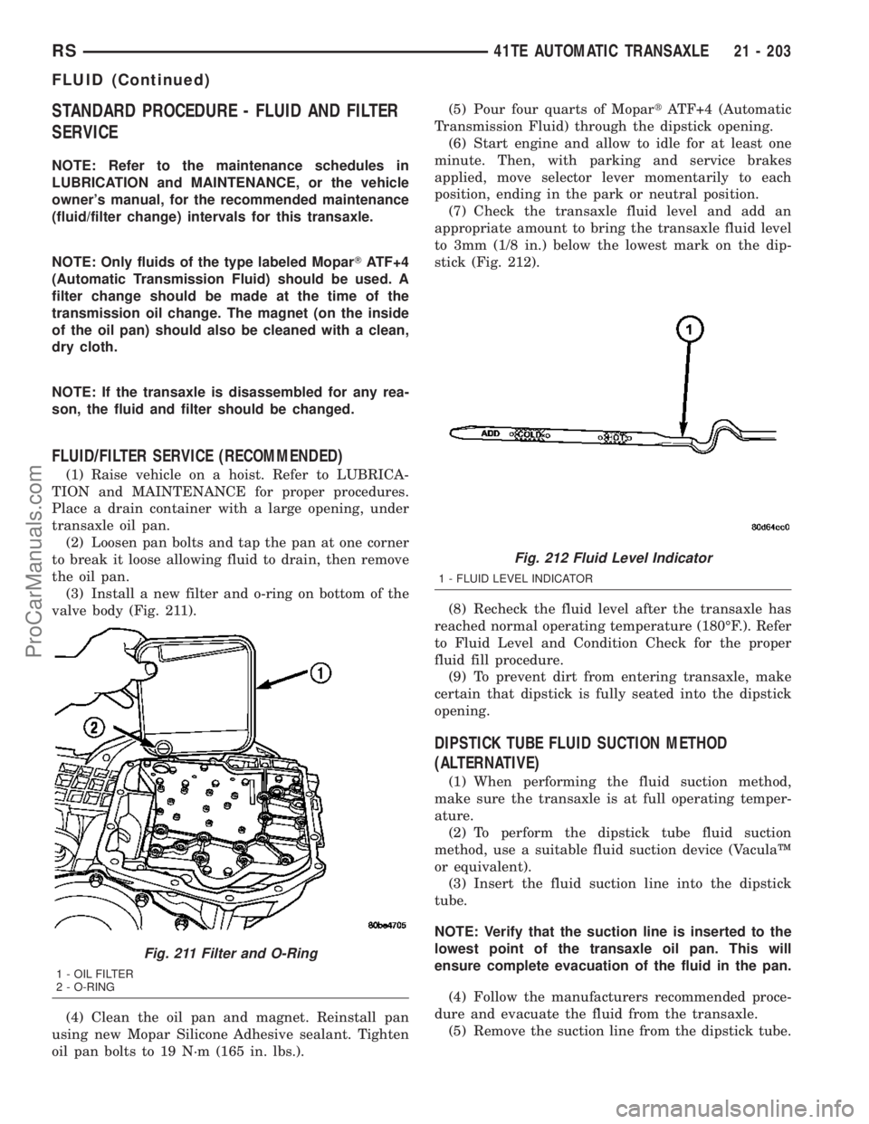
(3) Install a new filter and o-ring on bottom of the
valve body (Fig. 211).
(4) Clean the oil pan and magnet. Reinstall pan
using new Mopar Silicone Adhesive sealant. Tighten
oil pan bolts to 19 N´m (165 in. lbs.).(5) Pour four quarts of MopartATF+4 (Automatic
Transmission Fluid) through the dipstick opening.
(6) Start engine and allow to idle for at least one
minute. Then, with parking and service brakes
applied, move selector lever momentarily to each
position, ending in the park or neutral position.
(7) Check the transaxle fluid level and add an
appropriate amount to bring the transaxle fluid level
to 3mm (1/8 in.) below the lowest mark on the dip-
stick (Fig. 212).
(8) Recheck the fluid level after the transaxle has
reached normal operating temperature (180ÉF.). Refer
to Fluid Level and Condition Check for the proper
fluid fill procedure.
(9) To prevent dirt from entering transaxle, make
certain that dipstick is fully seated into the dipstick
opening.
DIPSTICK TUBE FLUID SUCTION METHOD
(ALTERNATIVE)
(1) When performing the fluid suction method,
make sure the transaxle is at full operating temper-
ature.
(2) To perform the dipstick tube fluid suction
method, use a suitable fluid suction device (VaculaŸ
or equivalent).
(3) Insert the fluid suction line into the dipstick
tube.
NOTE: Verify that the suction line is inserted to the
lowest point of the transaxle oil pan. This will
ensure complete evacuation of the fluid in the pan.
(4) Follow the manufacturers recommended proce-
dure and evacuate the fluid from the transaxle.
(5) Remove the suction line from the dipstick tube.
Fig. 211 Filter and O-Ring
1 - OIL FILTER
2 - O-RING
Fig. 212 Fluid Level Indicator
1 - FLUID LEVEL INDICATOR
RS41TE AUTOMATIC TRANSAXLE21 - 203
FLUID (Continued)
ProCarManuals.com
Page 1651 of 2177

(6) Pour four quarts of MopartATF+4 (Automatic
Transmission Fluid) through the dipstick opening.
(7) Start engine and allow to idle for at least one
minute. Then, with parking and service brakes
applied, move selector lever momentarily to each
position, ending in the park or neutral position.
(8) Check the transaxle fluid level and add an
appropriate amount to bring the transaxle fluid level
to 3mm (1/8 in.) below the lowest mark on the dip-
stick (Fig. 212).
(9) Recheck the fluid level after the transaxle has
reached normal operating temperature (180ÉF.).
(Refer to 21 - TRANSMISSION/TRANSAXLE/AUTO-
MATIC - 41TE/FLUID - STANDARD PROCEDURE)
(10) To prevent dirt from entering transaxle, make
certain that dipstick is fully seated into the dipstick
opening.
GEAR SHIFT CABLE
REMOVAL
(1) Disconnect battery cables.
(2) Remove battery shield.
(3) Remove battery.
(4) Remove speed control servo and position out of
way.
(5) Disconnect gear shift cable at manual valve
lever (Fig. 213).
(6) Disconnect gear shift cable from upper mount
bracket (Fig. 213).(7) Remove instrument panel lower silencer (Fig.
214).
(8) Remove knee bolster (Fig. 215).
(9) Disconnect gear shift cable from gear shift
lever (Fig. 216).
(10) Remove gear shift cable from column bracket
(Fig. 216).
(11) Disengage grommet from dash panel (Fig.
217) and remove gear shift cable from inside vehicle.
Fig. 213 Gearshift Cable at Transaxle - Typical
1 - MANUAL VALVE LEVER
2 - GEAR SHIFT CABLE
3 - UPPER MOUNT BRACKET
Fig. 214 Instrument Panel Lower Silencer
1 - INSTRUMENT PANEL LOWER SILENCER
Fig. 215 Knee Bolster
1 - KNEE BOLSTER
21 - 204 41TE AUTOMATIC TRANSAXLERS
FLUID (Continued)
ProCarManuals.com
Page 1694 of 2177

TORQUE CONVERTER CLUTCH (TCC)
In a standard torque converter, the impeller and
turbine are rotating at about the same speed and the
stator is freewheeling, providing no torque multipli-
cation. By applying the turbine's piston to the front
cover's friction material, a total converter engage-
ment can be obtained. The result of this engagement
is a direct 1:1 mechanical link between the engine
and the transmission.
The engagement and disengagement of the TCC
are automatic and controlled by the Powertrain Con-
trol Module (PCM). The engagement cannot be acti-
vated in the lower gears because it eliminates the
torque multiplication effect of the torque converter
necessary for acceleration. Inputs that determine
clutch engagement are: coolant temperature, vehicle
speed and throttle position. The torque converter
clutch is engaged by the clutch solenoid on the valve
body. The clutch will engage at approximately 56
km/h (35 mph) with light throttle, after the shift to
third gear.
REMOVAL
(1) Remove transmission and torque converter
from vehicle. (Refer to 21 - TRANSMISSION/TRANS-
AXLE/AUTOMATIC - 41TE - REMOVAL)
(2) Place a suitable drain pan under the converter
housing end of the transmission.
CAUTION: Verify that transmission is secure on the
lifting device or work surface, the center of gravity
of the transmission will shift when the torque con-
verter is removed creating an unstable condition.
The torque converter is a heavy unit. Use caution
when separating the torque converter from the
transmission.
(3) Pull the torque converter forward until the cen-
ter hub clears the oil pump seal.
(4) Separate the torque converter from the trans-
mission.
INSTALLATION
Check converter hub and drive notches for sharp
edges, burrs, scratches, or nicks. Polish the hub and
notches with 320/400 grit paper or crocus cloth if nec-
essary. The hub must be smooth to avoid damaging
the pump seal at installation.
(1) Lubricate converter hub and oil pump seal lip
with transmission fluid.
(2) Place torque converter in position on transmis-
sion.
CAUTION: Do not damage oil pump seal or bushing
while inserting torque converter into the front of the
transmission.(3) Align torque converter to oil pump seal open-
ing.
(4) Insert torque converter hub into oil pump.
(5) While pushing torque converter inward, rotate
converter until converter is fully seated in the oil
pump gears.
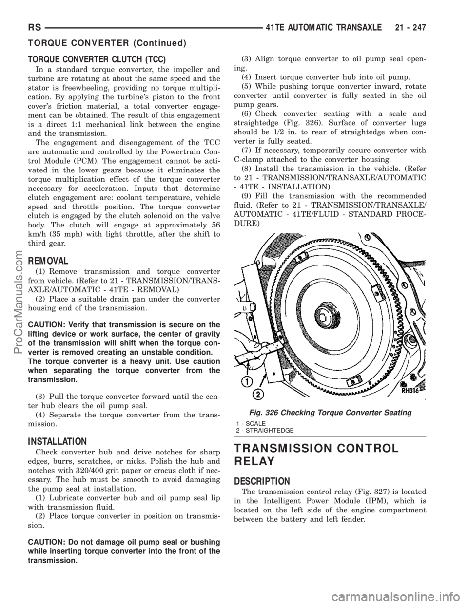
(6) Check converter seating with a scale and
straightedge (Fig. 326). Surface of converter lugs
should be 1/2 in. to rear of straightedge when con-
verter is fully seated.
(7) If necessary, temporarily secure converter with
C-clamp attached to the converter housing.
(8) Install the transmission in the vehicle. (Refer
to 21 - TRANSMISSION/TRANSAXLE/AUTOMATIC
- 41TE - INSTALLATION)
(9) Fill the transmission with the recommended
fluid. (Refer to 21 - TRANSMISSION/TRANSAXLE/
AUTOMATIC - 41TE/FLUID - STANDARD PROCE-
DURE)TRANSMISSION CONTROL
RELAY
DESCRIPTION
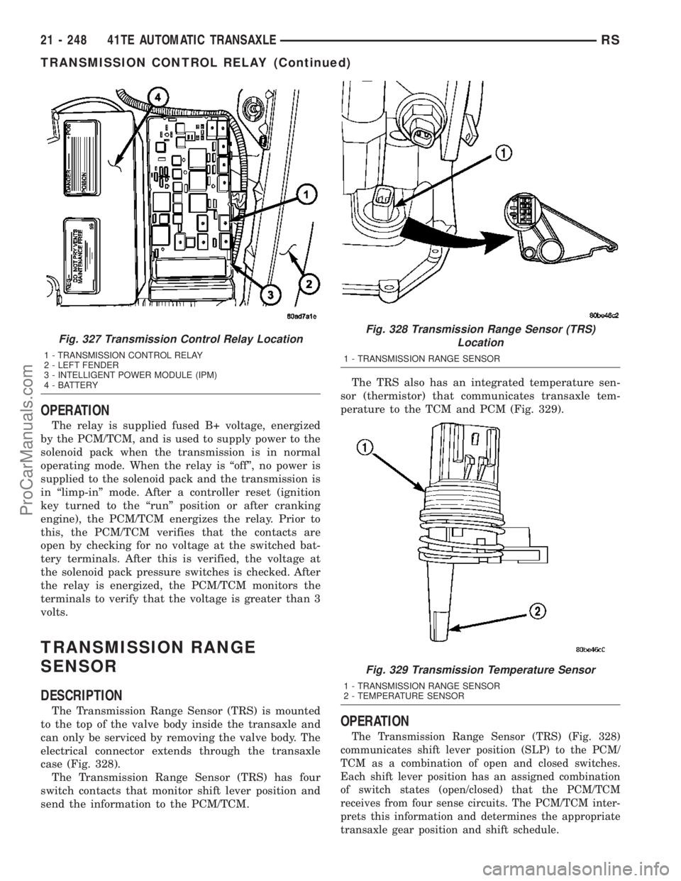
The transmission control relay (Fig. 327) is located
in the Intelligent Power Module (IPM), which is
located on the left side of the engine compartment
between the battery and left fender.
Fig. 326 Checking Torque Converter Seating
1 - SCALE
2 - STRAIGHTEDGE
RS41TE AUTOMATIC TRANSAXLE21 - 247
TORQUE CONVERTER (Continued)
ProCarManuals.com
Page 1695 of 2177

OPERATION
The relay is supplied fused B+ voltage, energized
by the PCM/TCM, and is used to supply power to the
solenoid pack when the transmission is in normal
operating mode. When the relay is ªoffº, no power is
supplied to the solenoid pack and the transmission is
in ªlimp-inº mode. After a controller reset (ignition
key turned to the ªrunº position or after cranking
engine), the PCM/TCM energizes the relay. Prior to
this, the PCM/TCM verifies that the contacts are
open by checking for no voltage at the switched bat-
tery terminals. After this is verified, the voltage at
the solenoid pack pressure switches is checked. After
the relay is energized, the PCM/TCM monitors the
terminals to verify that the voltage is greater than 3
volts.
TRANSMISSION RANGE
SENSOR
DESCRIPTION
The Transmission Range Sensor (TRS) is mounted
to the top of the valve body inside the transaxle and
can only be serviced by removing the valve body. The
electrical connector extends through the transaxle
case (Fig. 328).
The Transmission Range Sensor (TRS) has four
switch contacts that monitor shift lever position and
send the information to the PCM/TCM.The TRS also has an integrated temperature sen-
sor (thermistor) that communicates transaxle tem-
perature to the TCM and PCM (Fig. 329).
OPERATION
The Transmission Range Sensor (TRS) (Fig. 328)
communicates shift lever position (SLP) to the PCM/
TCM as a combination of open and closed switches.
Each shift lever position has an assigned combination
of switch states (open/closed) that the PCM/TCM
receives from four sense circuits. The PCM/TCM inter-
prets this information and determines the appropriate
transaxle gear position and shift schedule.
Fig. 327 Transmission Control Relay Location
1 - TRANSMISSION CONTROL RELAY
2 - LEFT FENDER
3 - INTELLIGENT POWER MODULE (IPM)
4 - BATTERY
Fig. 328 Transmission Range Sensor (TRS)
Location
1 - TRANSMISSION RANGE SENSOR
Fig. 329 Transmission Temperature Sensor
1 - TRANSMISSION RANGE SENSOR
2 - TEMPERATURE SENSOR
21 - 248 41TE AUTOMATIC TRANSAXLERS
TRANSMISSION CONTROL RELAY (Continued)
ProCarManuals.com
Page 1746 of 2177

(2) Apply specified lubricant to all pivoting and
sliding contact areas of component.
LUBRICANT USAGE
ENGINE OIL
²Door Hinges ± Hinge Pin and Pivot Contact
Areas
²Hood Hinges ± Pivot Points
²Liftgate Hinges
MOPARTSPRAY WHITE LUBE OR EQUIVALENT
²Door Check Straps
²Liftgate Latches
²Liftgate Prop Pivots²Ash Receiver
²Fuel Filler Door Remote Control Latch Mecha-
nism
²Parking Brake Mechanism
²Sliding Seat Tracks
²Liftgate Latch
MOPARTMultipurpose GREASE OR EQUIVALENT
²All Other Hood Mechanisms
MOPARTLOCK CYLINDER LUBRICANT OR
EQUIVALENT
²Door Lock Cylinders
²Liftgate Lock Cylinder
SPECIAL TOOLS
BODY
INDEX
DESCRIPTION FIGURE
STICK, TRIM C 4755 16
REMOVER, MOLDINGS C-4829 17
PLIERS, HEADLINER CLIP 6967 18
Fig. 16 STICK, TRIM C 4755
Fig. 17 REMOVER, MOLDINGS C-4829
Fig. 18 PLIERS, HEADLINER CLIP 6967
RSBODY23-13
BODY (Continued)
ProCarManuals.com
Page 1784 of 2177

FRONT FENDER
REMOVAL
(1) Remove headlamp housing. (Refer to 8 - ELEC-
TRICAL/LAMPS/LIGHTING - EXTERIOR/HEAD-
LAMP UNIT - REMOVAL)
(2) Remove mud guard.
(3) Remove inner splash shield.
(4) Remove fender to fascia nuts.
(5) Remove outboard cowl grille/fender bracket
screw.
(6) Remove fender bolt to lower rocker panel.
(7) Remove fender bolt to lower cowl.
(8) Pull fascia away from fender.
(9) Remove bolts attaching fender to upper rail.
(10) Remove fender from vehicle (Fig. 8).
INSTALLATION
(1) Place fender in position on vehicle.
(2) From inside engine compartment, start the
center upper rail bolt. install all the bolts attaching
fender to upper rail and tighten.
(3) Install fender to lower cowl panel bolt.
(4) Install fender to rocker panel bolt.
(5) Place fascia into position.
(6) Install outboard cowl grille/fender bracket
screw.
(7) Install fender to fascia nuts.
(8) Install inner splash shield.
(9) Install mud guard.(10) Install headlamp assembly. (Refer to 8 -
ELECTRICAL/LAMPS/LIGHTING - EXTERIOR/
HEADLAMP UNIT - INSTALLATION)
(11) Check fender for flush and gap.
FUEL FILL DOOR
REMOVAL
(1) Remove left quarter trim panel.
(2) Remove water shield patch covering access hole
in C-pillar.
(3) Disengage latch release link from clip on fuel
fill blocker latch arm (Fig. 12).
(4) Open fuel fill door.
(5) Remove screws holding fuel fill neck to fuel
filler housing.
(6) Position fuel fill neck out of the way.
(7) Reaching inside fuel filler housing, release clips
holding housing to quarter panel (Fig. 9).
(8) Remove fuel fill door from vehicle.
(9) Disengage clip holding link to fuel fill door
(Fig. 13).
(10) Remove link from fuel fill door.
INSTALLATION
(1) Install spring to housing and door
(2) Snap door into housing.
(3) Insert lockout link into clip on fuel fill door.
(4) Engage clip to hold link to fuel fill door.
(5) Insert lockout link through grommet in panel
between inner and outer quarter panel.
(6) Close fuel fill door.
(7) Install fuel filler housing to outer quarter
panel.
Fig. 8 FENDER
1 - FASTENERS
2 - FENDER
3 - FASTENERS
Fig. 9 FUEL FILLER HOUSING AND DOOR
1 - FUEL FILLER HOUSING W/LATCH
2 - CLIP
3 - FUEL FILLER HOUSING DOOR
4 - CLIPS
5 - FIX CLIP
RSEXTERIOR23-51
ProCarManuals.com