light CHRYSLER CARAVAN 2003 Service Manual
[x] Cancel search | Manufacturer: CHRYSLER, Model Year: 2003, Model line: CARAVAN, Model: CHRYSLER CARAVAN 2003Pages: 2177, PDF Size: 59.81 MB
Page 1719 of 2177
REMOVAL - TIRE AND WHEEL ASSEMBLY
(STEEL WHEEL)
(1) Raise the vehicle so the tire and wheel assem-
bly clears ground level.
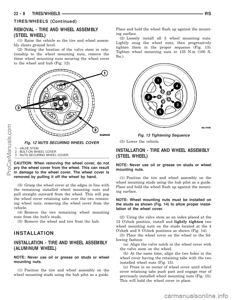
(2) Noting the location of the valve stem in rela-
tionship to the wheel mounting nuts, remove the
three wheel mounting nuts securing the wheel cover
to the wheel and hub (Fig. 12).
CAUTION: When removing the wheel cover, do not
pry the wheel cover from the wheel. This can result
in damage to the wheel cover. The wheel cover is
removed by pulling it off the wheel by hand.
(3) Grasp the wheel cover at the edges in line with
the remaining installed wheel mounting nuts and
pull straight outward from the wheel. This will pop
the wheel cover retaining tabs over the two remain-
ing wheel nuts, removing the wheel cover from the
vehicle.
(4) Remove the two remaining wheel mounting
nuts from the hub's studs.
(5) Remove the wheel and tire from the hub.
INSTALLATION
INSTALLATION - TIRE AND WHEEL ASSEMBLY
(ALUMINUM WHEEL)
NOTE: Never use oil or grease on studs or wheel
mounting nuts.
(1) Position the tire and wheel assembly on the
wheel mounting studs using the hub pilot as a guide.Place and hold the wheel flush up against the mount-
ing surface.
(2) Loosely install all 5 wheel mounting nuts.
Lightly snug the wheel nuts, then progressively
tighten them in the proper sequence (Fig. 13).
Tighten wheel mounting nuts to 135 N´m (100 ft.
lbs.).
(3) Lower the vehicle.
INSTALLATION - TIRE AND WHEEL ASSEMBLY
(STEEL WHEEL)
NOTE: Never use oil or grease on studs or wheel
mounting nuts.
(1) Position the tire and wheel assembly on the
wheel mounting studs using the hub pilot as a guide.
Place and hold the wheel flush up against the mount-
ing surface.
NOTE: Wheel mounting nuts must be installed on
the studs as shown (Fig. 14) to allow proper instal-
lation of the wheel cover.
(2) Using the valve stem as an index placed at the
12 O'clock position, install andlightly tightentwo
wheel mounting nuts on the studs located at the 4
O'clock and 8 O'clock positions as shown (Fig. 14).
(3) Place the wheel cover on the wheel in the fol-
lowing fashion:
(a) Align the valve notch in the wheel cover with
the valve stem on the wheel.
(b) At the same time, align the two holes in the
wheel cover having the retaining tabs with the two
installed wheel nuts (Fig. 15).
(c) Press in on center of wheel cover until wheel
cover retaining tabs push past and engage rear of
previously installed wheel mounting nuts (Fig. 15).
This will hold the wheel cover in place.
Fig. 12 NUTS SECURING WHEEL COVER
1 - VALVE STEM
2 - BOLT-ON WHEEL COVER
3 - NUTS SECURING WHEEL COVER
Fig. 13 Tightening Sequence
22 - 8 TIRES/WHEELSRS
TIRES/WHEELS (Continued)
ProCarManuals.com
Page 1720 of 2177

(4) Install andlightly tightenthe three remain-
ing wheel mounting nuts, securing the wheel cover in
place (Fig. 12).
(5) Progressively tighten all five wheel mounting
nuts in the proper sequence (Fig. 16). Tighten wheel
nuts to a torque of 135 N´m (100 ft. lbs.).
(6) Lower the vehicle.
TIRE PRESSURE MONITORING
DESCRIPTION
Some versions of this vehicle are equipped with a
Tire Pressure Monitoring (TPM) system. It monitors
air pressure in the four road tires (excludes spare).
Pressure in the spare tire is not monitored.
There is a sensor (transmitter) in each of the vehi-
cle's four road wheels. The system alerts the driver
when tire pressure falls outside predetermined
thresholds (pressure too low or too high). A message
is then displayed on the Electronic Vehicle Informa-
tion Center (EVIC) located in the overhead console.
For further information, refer to the Owners Man-
ual or the appropriate diagnostic information.
OPERATION
The Tire Pressure Monitoring (TPM) system uses
radio and sensor technology to monitor tire air pres-
sure levels. Sensors, mounted to each road wheel as
part of the valve stem, transmit tire pressure read-
ings to a receiver located in the overhead console.
These transmissions occur once every minute at
speeds over 20 mph (32 km/h). The Tire Pressure
Monitoring system remains active even if no tire
pressure related message is displayed in the EVIC.
If any road tire pressure has exceeded the low or
high pressure threshold (refer to chart below), the
TPM system will display a message in the EVIC and
sound a chime. This message will be displayed for
the rest of the ignition cycle, or until either the Low/
High Tire pressure condition has been corrected. If
the C/T, MENU, STEP or RESET button is pressed,
the message is replaced by the new message
requested; however, if the Low/High Tire condition
has not been corrected, the Low/High Tire pressure
message will again be displayed.
Fig. 14 TWO WHEEL MOUNTING NUTS INSTALLED
1 - WHEEL
2 - VALVE STEM
3 - HUB PILOT
4 - NUTS
Fig. 15 WHEEL COVER INSTALLATION OVER TWO
NUTS
1 - RETAINING TABS
2 - VALVE STEM
3 - BOLT-ON WHEEL COVER
Fig. 16 NUT TIGHTENING SEQUENCE
RSTIRES/WHEELS22-9
TIRES/WHEELS (Continued)
ProCarManuals.com
Page 1724 of 2177
TIRES
DESCRIPTION
DESCRIPTION - TIRE
Tires are designed and engineered for each specific
vehicle. They provide the best overall performance
for normal operation. The ride and handling charac-
teristics match the vehicle's requirements. With
proper care they will give excellent reliability, trac-
tion, skid resistance, and tread life.
Driving habits have more effect on tire life than
any other factor. Careful drivers will obtain, in most
cases, much greater mileage than severe use or care-
less drivers. A few of the driving habits which will
shorten the life of any tire are:
²Rapid acceleration
²Severe application of brakes
²High-speed driving
²Taking turns at excessive speeds
²Striking curbs and other obstacles
²Operating vehicle with over or under inflated
tire pressures
Radial ply tires are more prone to irregular tread
wear. It is important to follow the tire rotation inter-
val shown in the section on Tire Rotation. This will
help to achieve a greater tread-life potential.
TIRE IDENTIFICATION
Tire type, size, load index and speed rating are
encoded in the letters and numbers imprinted on the
side wall of the tire. Refer to the Tire Identification
chart to decipher the code. For example purposes, the
tire size P225/60 R 16 97 T is used in the chart. An
All Season type tire will also have eitherM+S,M&
SorM-S(indicating mud and snow traction)
imprinted on the side wall. An Extra or Light Load
marking ªXLº or ªLLº may also be listed on the side-
wall. The absence of an ªXLº or ªLLº marking infers
a standard load tire.
TIRE IDENTIFICATION
PTIRE TYPE (Not
present on all tires)P - Passenger
T - Temporary
C - Commercial
LT - Light Truck
225SECTIONAL WIDTHSHOWN IN
MILLIMETERS
60ASPECT RATIOSECTIONAL HEIGHT
÷ SECTIONAL WIDTH
(Refer to Aspect Ratio
Figure 22 )
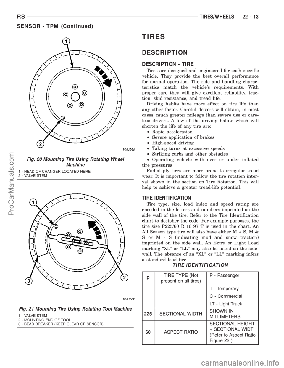
Fig. 20 Mounting Tire Using Rotating Wheel
Machine
1 - HEAD OF CHANGER LOCATED HERE
2 - VALVE STEM
Fig. 21 Mounting Tire Using Rotating Tool Machine
1 - VALVE STEM
2 - MOUNTING END OF TOOL
3 - BEAD BREAKER (KEEP CLEAR OF SENSOR)
RSTIRES/WHEELS22-13
SENSOR - TPM (Continued)
ProCarManuals.com
Page 1731 of 2177
(1) Place the wheel cover on the wheel in the fol-
lowing fashion:
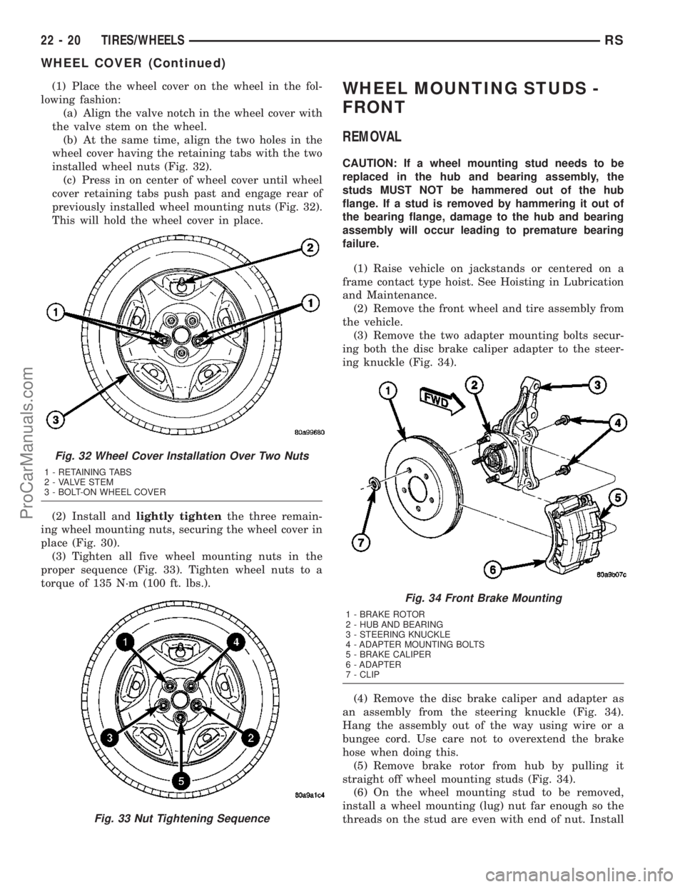
(a) Align the valve notch in the wheel cover with
the valve stem on the wheel.
(b) At the same time, align the two holes in the
wheel cover having the retaining tabs with the two
installed wheel nuts (Fig. 32).
(c) Press in on center of wheel cover until wheel
cover retaining tabs push past and engage rear of
previously installed wheel mounting nuts (Fig. 32).
This will hold the wheel cover in place.
(2) Install andlightly tightenthe three remain-
ing wheel mounting nuts, securing the wheel cover in
place (Fig. 30).
(3) Tighten all five wheel mounting nuts in the
proper sequence (Fig. 33). Tighten wheel nuts to a
torque of 135 N´m (100 ft. lbs.).WHEEL MOUNTING STUDS -
FRONT
REMOVAL
CAUTION: If a wheel mounting stud needs to be
replaced in the hub and bearing assembly, the
studs MUST NOT be hammered out of the hub
flange. If a stud is removed by hammering it out of
the bearing flange, damage to the hub and bearing
assembly will occur leading to premature bearing
failure.
(1) Raise vehicle on jackstands or centered on a
frame contact type hoist. See Hoisting in Lubrication
and Maintenance.
(2) Remove the front wheel and tire assembly from
the vehicle.
(3) Remove the two adapter mounting bolts secur-
ing both the disc brake caliper adapter to the steer-
ing knuckle (Fig. 34).
(4) Remove the disc brake caliper and adapter as
an assembly from the steering knuckle (Fig. 34).
Hang the assembly out of the way using wire or a
bungee cord. Use care not to overextend the brake
hose when doing this.
(5) Remove brake rotor from hub by pulling it
straight off wheel mounting studs (Fig. 34).
(6) On the wheel mounting stud to be removed,
install a wheel mounting (lug) nut far enough so the
threads on the stud are even with end of nut. Install
Fig. 32 Wheel Cover Installation Over Two Nuts
1 - RETAINING TABS
2 - VALVE STEM
3 - BOLT-ON WHEEL COVER
Fig. 33 Nut Tightening Sequence
Fig. 34 Front Brake Mounting
1 - BRAKE ROTOR
2 - HUB AND BEARING
3 - STEERING KNUCKLE
4 - ADAPTER MOUNTING BOLTS
5 - BRAKE CALIPER
6 - ADAPTER
7 - CLIP
22 - 20 TIRES/WHEELSRS
WHEEL COVER (Continued)
ProCarManuals.com
Page 1735 of 2177

DIAGNOSIS AND TESTING
DIAGNOSIS AND TESTING - WATER LEAKS
Water leaks can be caused by poor sealing,
improper body component alignment, body seam
porosity, missing plugs, or blocked drain holes. Cen-
trifugal and gravitational force can cause water to
drip from a location away from the actual leak point,
making leak detection difficult. All body sealing
points should be water tight in normal wet-driving
conditions. Water flowing downward from the front of
the vehicle should not enter the passenger or luggage
compartment. Moving sealing surfaces will not
always seal water tight under all conditions. At
times, side glass or door seals will allow water to
enter the passenger compartment during high pres-
sure washing or hard driving rain (severe) condi-
tions. Overcompensating on door or glass
adjustments to stop a water leak that occurs under
severe conditions can cause premature seal wear and
excessive closing or latching effort. After completing
a repair, water test vehicle to verify leak has stopped
before returning vehicle to use.
VISUAL INSPECTION BEFORE WATER LEAK TESTS
Verify that floor and body plugs are in place, body
drains are clear, and body components are properly
aligned and sealed. If component alignment or seal-
ing is necessary, refer to the appropriate section of
this group for proper procedures.
WATER LEAK TESTS
WARNING: DO NOT USE ELECTRIC SHOP LIGHTS
OR TOOLS IN WATER TEST AREA. PERSONAL
INJURY CAN RESULT.
When the conditions causing a water leak have
been determined, simulate the conditions as closely
as possible.
²If a leak occurs with the vehicle parked in a
steady light rain, flood the leak area with an open-
ended garden hose.
²If a leak occurs while driving at highway speeds
in a steady rain, test the leak area with a reasonable
velocity stream or fan spray of water. Direct the
spray in a direction comparable to actual conditions.
²If a leak occurs when the vehicle is parked on an
incline, hoist the end or side of the vehicle to simu-
late this condition. This method can be used when
the leak occurs when the vehicle accelerates, stops or
turns. If the leak occurs on acceleration, hoist the
front of the vehicle. If the leak occurs when braking,
hoist the back of the vehicle. If the leak occurs on left
turns, hoist the left side of the vehicle. If the leak
occurs on right turns, hoist the right side of the vehi-cle. For hoisting recommendations (Refer to LUBRI-
CATION & MAINTENANCE/HOISTING -
STANDARD PROCEDURE).
WATER LEAK DETECTION
To detect a water leak point-of-entry, do a water
test and watch for water tracks or droplets forming
on the inside of the vehicle. If necessary, remove inte-
rior trim covers or panels to gain visual access to the
leak area. If the hose cannot be positioned without
being held, have someone help do the water test.
Some water leaks must be tested for a considerable
length of time to become apparent. When a leak
appears, find the highest point of the water track or
drop. The highest point usually will show the point of
entry. After leak point has been found, repair the
leak and water test to verify that the leak has
stopped.
Locating the entry point of water that is leaking
into a cavity between panels can be difficult. The
trapped water may splash or run from the cavity,
often at a distance from the entry point. Most water
leaks of this type become apparent after accelerating,
stopping, turning, or when on an incline.
MIRROR INSPECTION METHOD
When a leak point area is visually obstructed, use
a suitable mirror to gain visual access. A mirror can
also be used to deflect light to a limited-access area
to assist in locating a leak point.
BRIGHT LIGHT LEAK TEST METHOD
Some water leaks in the luggage compartment can
be detected without water testing. Position the vehicle
in a brightly lit area. From inside the darkened lug-
gage compartment inspect around seals and body
seams. If necessary, have a helper direct a drop light
over the suspected leak areas around the luggage com-
partment. If light is visible through a normally sealed
location, water could enter through the opening.
PRESSURIZED LEAK TEST METHOD
When a water leak into the passenger compart-
ment cannot be detected by water testing, pressurize
the passenger compartment and soap test exterior of
the vehicle. To pressurize the passenger compart-
ment, close all doors and windows, start engine, and
set heater control to high blower in HEAT position. If
engine can not be started, connect a charger to the
battery to ensure adequate voltage to the blower.
With interior pressurized, apply dish detergent solu-
tion to suspected leak area on the exterior of the
vehicle. Apply detergent solution with spray device or
soft bristle brush. If soap bubbles occur at a body
seam, joint, seal or gasket, the leak entry point could
be at that location.
23 - 2 BODYRS
BODY (Continued)
ProCarManuals.com
Page 1737 of 2177

RIGID, SEMI-RIGID, AND FLEXIBLE PLASTIC PARTS TYPES
CODE FAMILY NAME COMMON TRADE NAME TYPICAL APPLICATION
ASA ACRYLONITRILE STYRENE
ACRYLITELURAN S CONSOLES, GRILLES
ABS ACRYLONITRILE
BUTADIENE STYRENETERLURAN9A9PILLARS, CONSOLES,
GRILLES
ABS/PC ABS/PC ALLOY PULSE, PROLOY,
BAYBLENDDOORS, INSTRUMENT
PANELS
ABS/PVC ABS/PV ALLOY PROLOY, PULSE, LUSTRAN,
CYCLOVINDOOR PANELS, GRILLES,
TRIM
BMC BULK MOLDING
COMPOUNDBMC FENDER EXTENSIONS
EMA EHTYLENE METHYL
ACRYLATE/IONOMERSURLYN, EMA, IONOMER BUMPER GUARDS, PADS
METTON METTON METTON GRILLES, KICK PANELS,
RUNNING BOARDS
MPPO MODIFIED
POLYPHENYLENE OXIDEMPPO SPOILER ASSEMBLY
PA POLYAMID ZYTEL, VYDYNE, PA,
MINLONFENDERS, QUARTER PANELS
PET THERMOPLASTIC
POLYESTERRYNITE TRIM
PBT/PPO PBT/PPO ALLOY GERMAX CLADDINGS
PBTP POLYBUTYLENE
THEREPTHALATEPBT, PBTP, POCAN, VALOX WHEEL COVERS, FENDERS,
GRILLES
PBTP/EEBC POLYBUTYLENE
THEREPTHALATE/EEBC
ALLOYBEXLOY,9M9, PBTP/EEBC FASCIAS, ROCKER PANEL,
MOLDINGS
PC POLYCARBONATE LEXAN, MERLON, CALIBRE,
MAKROLON PCTAIL LIGHT LENSES, IP TRIM,
VALANCE PANELS
PC/ABS PC/ABS ALLOY GERMAX, BAY BLENDS,
PULSEDOORS, INSTRUMENT
PANELS
PPO POLYPHENYLENE OXIDE AZDEL, HOSTALEN,
MARLEX, PRFAX, NORYL,
GTX, PPOINTERIOR TRIM, DOOR
PANELS, SPLASH SHIELDS,
STEERING COLUMN SHROUD
PPO/PA POLYPHENYLENE/
POLYAMIDPPO/PA, GTX 910 FENDERS, QUARTER PANELS
PR/FV FIBERGLASS REINFORCED
PLASTICFIBERGLASS, FV, PR/FV BODY PANELS
PS POLYSTYRENE LUSTREX, STYRON, PS DOOR PANELS, DASH
PANELS
RTM RESIN TRANSFER
MOLDING COMPOUNDRTM BODY PANELS
SMC SHEET MOLDED
COMPOUNDSMC BODY PANELS
TMC TRANSFER MOLDING
COMPOUNDTMC GRILLES
23 - 4 BODYRS
BODY (Continued)
ProCarManuals.com
Page 1739 of 2177
PANEL SECTIONING
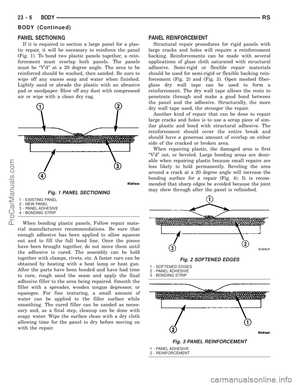
If it is required to section a large panel for a plas-
tic repair, it will be necessary to reinforce the panel
(Fig. 1). To bond two plastic panels together, a rein-
forcement must overlap both panels. The panels
must be ªV'dº at a 20 degree angle. The area to be
reinforced should be washed, then sanded. Be sure to
wipe off any excess soap and water when finished.
Lightly sand or abrade the plastic with an abrasive
pad or sandpaper. Blow off any dust with compressed
air or wipe with a clean dry rag.
When bonding plastic panels, Follow repair mate-
rial manufacturers recommendations. Be sure that
enough adhesive has been applied to allow squeeze
out and to fill the full bond line. Once the pieces
have been brought together, do not move them until
the adhesive is cured. The assembly can be held
together with clamps, rivets, etc. A faster cure can be
obtained by heating with a heat lamp or heat gun.
After the parts have been bonded and have had time
to cure, rough sand the seam and apply the final
adhesive filler to the area being repaired. Smooth the
filler with a spreader, wooden tongue depressor, or
squeegee. For fine texturing, a small amount of
water can be applied to the filler surface while
smoothing. The cured filler can be sanded as neces-
sary and, as a final step, cleanup can be done with
soapy water. Wipe the surface clean with a dry cloth
allowing time for the panel to dry before moving on
with the repair.
PANEL REINFORCEMENT
Structural repair procedures for rigid panels with
large cracks and holes will require a reinforcement
backing. Reinforcements can be made with several
applications of glass cloth saturated with structural
adhesive. Semi-rigid or flexible repair materials
should be used for semi-rigid or flexible backing rein-
forcement (Fig. 2) and (Fig. 3). Open meshed fiber-
glass dry wall tape can be used to form a
reinforcement. The dry wall tape allows the resin to
penetrate through and make a good bond between
the panel and the adhesive. Structurally, the more
dry wall tape used, the stronger the repair.
Another kind of repair that can be done to repair
large cracks and holes is to use a scrap piece of sim-
ilar plastic and bond with structural adhesive. The
reinforcement should cover the entire break and
should have a generous amount of overlap on either
side of the cracked or broken area.
When repairing plastic, the damaged area is first
ªV'dº out, or beveled. Large bonding areas are desir-
able when repairing plastic because small repairs are
less likely to hold permanently. Beveling the area
around a crack at a 20 degree angle will increase the
bonding surface for a repair (Fig. 4). It is recom-
mended that sharp edges be avoided because the joint
may show through after the panel is refinished.
Fig. 1 PANEL SECTIONING
1 - EXISTING PANEL
2 - NEW PANEL
3 - PANEL ADHESIVE
4 - BONDING STRIP
Fig. 2 SOFTENED EDGES
1 - SOFTENED EDGES
2 - PANEL ADHESIVE
3 - BONDING STRIP
Fig. 3 PANEL REINFORCEMENT
1 - PANEL ADHESIVE
2 - REINFORCEMENT
23 - 6 BODYRS
BODY (Continued)
ProCarManuals.com
Page 1772 of 2177
DECKLID/HATCH/LIFTGATE/TAILGATE
TABLE OF CONTENTS
page page
EXTERIOR HANDLE
REMOVAL.............................39
INSTALLATION.........................39
HINGE
REMOVAL.............................39
INSTALLATION.........................39
LATCH
REMOVAL.............................40
INSTALLATION.........................40
LATCH STRIKER
REMOVAL.............................40
INSTALLATION.........................40
LIFTGATE
REMOVAL.............................41
INSTALLATION.........................41
LIFTGATE SPOILER
REMOVAL.............................41INSTALLATION.........................41
LOCK CYLINDER
REMOVAL.............................41
INSTALLATION.........................41
SUPPORT CYLINDER
REMOVAL.............................42
INSTALLATION.........................42
TRIM PANEL
REMOVAL.............................42
INSTALLATION.........................43
SLAM BUMPER
REMOVAL
REMOVAL...........................43
REMOVAL - LIFTGATE SIDE.............43
INSTALLATION
INSTALLATION.......................43
INSTALLATION - LIFTGATE SIDE.........43
EXTERIOR HANDLE
REMOVAL
(1) Remove liftgate trim panel. (Refer to 23 -
BODY/DECKLID/HATCH/LIFTGATE/TAILGATE/
TRIM PANEL - REMOVAL)
(2) Disconnect the exterior handle electrical con-
nectors.
(3) Remove the two outer screws and the two inner
screws.
(4) Remove the exterior handle/license plate light
assembly.
INSTALLATION
(1) Route the exterior handle electrical connector
through the door and position handle.
(2) Install the two out screws and tighten to 20
N´m (15 ft. lbs.).
(3) Install the two inner bolts and tighten to 40
N´m (30 ft. lbs.).
(4) Connect the electrical connector.
(5) Install the trim panel. (Refer to 23 - BODY/
DECKLID/HATCH/LIFTGATE/TAILGATE/TRIM
PANEL - INSTALLATION)
HINGE
REMOVAL
(1) Release liftgate latch and open liftgate.
(2) Support liftgate on a suitable lifting device in
the full open position.
(3) Apply several layers of duct tape on the outside
of to roof across the gap to the lift gate to hold the
liftgate in position.
(4) Remove bolts attaching liftgate hinge to roof
header.
(5) Disconnect VTSS switch from the body har-
ness.
(6) Remove bolts attaching hinge to liftgate (Fig.
1).
(7) Remove hinge from vehicle.
INSTALLATION
(1) If necessary, paint replacement hinge before
installation.
(2) Place hinge in position on vehicle.
(3) Align hinge to marks on liftgate.
(4) Install bolts attaching hinge to liftgate (Fig. 1).
Tighten bolts to 33 N´m (24 ft. lbs.) torque.
(5) Align hinge to marks on roof header.
(6) Install bolts attaching liftgate hinge to roof
header. Tighten outer two bolts to 33 N´m (24 ft. lbs.)
torque. The sheet medal screw at center 12 N´m (105
in. lbs.)
(7) Remove duct tape from roof and liftgate.
RSDECKLID/HATCH/LIFTGATE/TAILGATE23-39
ProCarManuals.com
Page 1784 of 2177

FRONT FENDER
REMOVAL
(1) Remove headlamp housing. (Refer to 8 - ELEC-
TRICAL/LAMPS/LIGHTING - EXTERIOR/HEAD-
LAMP UNIT - REMOVAL)
(2) Remove mud guard.
(3) Remove inner splash shield.
(4) Remove fender to fascia nuts.
(5) Remove outboard cowl grille/fender bracket
screw.
(6) Remove fender bolt to lower rocker panel.
(7) Remove fender bolt to lower cowl.
(8) Pull fascia away from fender.
(9) Remove bolts attaching fender to upper rail.
(10) Remove fender from vehicle (Fig. 8).
INSTALLATION
(1) Place fender in position on vehicle.
(2) From inside engine compartment, start the
center upper rail bolt. install all the bolts attaching
fender to upper rail and tighten.
(3) Install fender to lower cowl panel bolt.
(4) Install fender to rocker panel bolt.
(5) Place fascia into position.
(6) Install outboard cowl grille/fender bracket
screw.
(7) Install fender to fascia nuts.
(8) Install inner splash shield.
(9) Install mud guard.(10) Install headlamp assembly. (Refer to 8 -
ELECTRICAL/LAMPS/LIGHTING - EXTERIOR/
HEADLAMP UNIT - INSTALLATION)
(11) Check fender for flush and gap.
FUEL FILL DOOR
REMOVAL
(1) Remove left quarter trim panel.
(2) Remove water shield patch covering access hole
in C-pillar.
(3) Disengage latch release link from clip on fuel
fill blocker latch arm (Fig. 12).
(4) Open fuel fill door.
(5) Remove screws holding fuel fill neck to fuel
filler housing.
(6) Position fuel fill neck out of the way.
(7) Reaching inside fuel filler housing, release clips
holding housing to quarter panel (Fig. 9).
(8) Remove fuel fill door from vehicle.
(9) Disengage clip holding link to fuel fill door
(Fig. 13).
(10) Remove link from fuel fill door.
INSTALLATION
(1) Install spring to housing and door
(2) Snap door into housing.
(3) Insert lockout link into clip on fuel fill door.
(4) Engage clip to hold link to fuel fill door.
(5) Insert lockout link through grommet in panel
between inner and outer quarter panel.
(6) Close fuel fill door.
(7) Install fuel filler housing to outer quarter
panel.
Fig. 8 FENDER
1 - FASTENERS
2 - FENDER
3 - FASTENERS
Fig. 9 FUEL FILLER HOUSING AND DOOR
1 - FUEL FILLER HOUSING W/LATCH
2 - CLIP
3 - FUEL FILLER HOUSING DOOR
4 - CLIPS
5 - FIX CLIP
RSEXTERIOR23-51
ProCarManuals.com
Page 1803 of 2177
INSTRUMENT PANEL TOP PAD
ASSEMBLY
REMOVAL
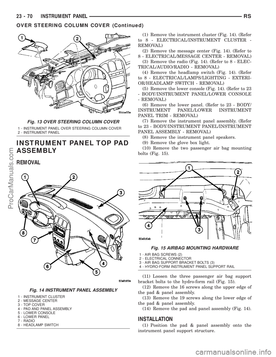
(1) Remove the instrument cluster (Fig. 14). (Refer
to 8 - ELECTRICAL/INSTRUMENT CLUSTER -
REMOVAL)
(2) Remove the message center (Fig. 14). (Refer to
8 - ELECTRICAL/MESSAGE CENTER - REMOVAL)
(3) Remove the radio (Fig. 14). (Refer to 8 - ELEC-
TRICAL/AUDIO/RADIO - REMOVAL)
(4) Remove the headlamp switch (Fig. 14). (Refer
to 8 - ELECTRICAL/LAMPS/LIGHTING - EXTERI-
OR/HEADLAMP SWITCH - REMOVAL)
(5) Remove the lower console (Fig. 14). (Refer to 23
- BODY/INSTRUMENT PANEL/LOWER CONSOLE
- REMOVAL)
(6) Remove the lower panel. (Refer to 23 - BODY/
INSTRUMENT PANEL/LOWER INSTRUMENT
PANEL TRIM - REMOVAL)
(7) Remove the instrument panel assembly. (Refer
to 23 - BODY/INSTRUMENT PANEL/INSTRUMENT
PANEL ASSEMBLY - REMOVAL)
(8) Remove the instrument panel speakers.
(9) Remove the glove box light.
(10) Remove the two passenger air bag mounting
bolts (Fig. 15).
(11) Loosen the three passenger air bag support
bracket bolts to the hydro-form rail (Fig. 15).
(12) Remove the 16 screws along the upper edge of
the pad & panel assembly.
(13) Remove the 19 screws along the lower edge of
the pad & panel assembly.
(14) Remove the pad and panel assembly (Fig. 14).
INSTALLATION
(1) Position the pad & panel assembly onto the
instrument panel support structure.
Fig. 13 OVER STEERING COLUMN COVER
1 - INSTRUMENT PANEL OVER STEERING COLUMN COVER
2 - INSTRUMENT PANEL
Fig. 14 INSTRUMENT PANEL ASSEMBLY
1 - INSTRUMENT CLUSTER
2 - MESSAGE CENTER
3 - TOP COVER
4 - PAD AND PANEL ASSEMBLY
5 - LOWER CONSOLE
6 - LOWER PANEL
7 - RADIO
8 - HEADLAMP SWITCH
Fig. 15 AIRBAG MOUNTING HARDWARE
1 - AIR BAG SCREWS (2)
2 - ELECTRICAL CONNECTOR
3 - AIR BAG SUPPORT BRACKET BOLTS (3)
4 - HYDRO-FORM INSTRUMENT PANEL SUPPORT RAIL
23 - 70 INSTRUMENT PANELRS
OVER STEERING COLUMN COVER (Continued)
ProCarManuals.com