power steering fluid CHRYSLER CARAVAN 2003 User Guide
[x] Cancel search | Manufacturer: CHRYSLER, Model Year: 2003, Model line: CARAVAN, Model: CHRYSLER CARAVAN 2003Pages: 2177, PDF Size: 59.81 MB
Page 35 of 2177
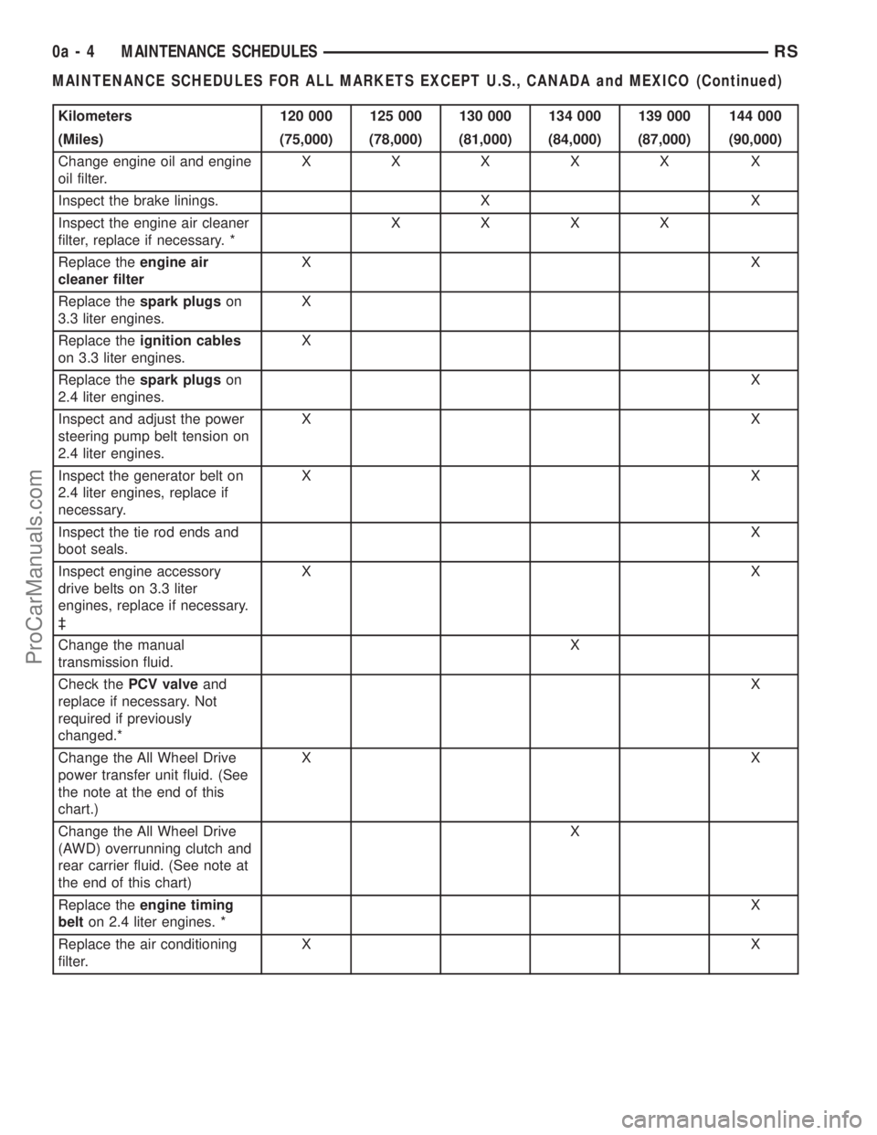
Kilometers 120 000 125 000 130 000 134 000 139 000 144 000
(Miles) (75,000) (78,000) (81,000) (84,000) (87,000) (90,000)
Change engine oil and engine
oil filter.XXXXX X
Inspect the brake linings. X X
Inspect the engine air cleaner
filter, replace if necessary. *XXXX
Replace theengine air
cleaner filterXX
Replace thespark plugson
3.3 liter engines.X
Replace theignition cables
on 3.3 liter engines.X
Replace thespark plugson
2.4 liter engines.X
Inspect and adjust the power
steering pump belt tension on
2.4 liter engines.XX
Inspect the generator belt on
2.4 liter engines, replace if
necessary.XX
Inspect the tie rod ends and
boot seals.X
Inspect engine accessory
drive belts on 3.3 liter
engines, replace if necessary.
³XX
Change the manual
transmission fluid.X
Check thePCV valveand
replace if necessary. Not
required if previously
changed.*X
Change the All Wheel Drive
power transfer unit fluid. (See
the note at the end of this
chart.)XX
Change the All Wheel Drive
(AWD) overrunning clutch and
rear carrier fluid. (See note at
the end of this chart)X
Replace theengine timing
belton 2.4 liter engines. *X
Replace the air conditioning
filter.XX
0a - 4 MAINTENANCE SCHEDULESRS
MAINTENANCE SCHEDULES FOR ALL MARKETS EXCEPT U.S., CANADA and MEXICO (Continued)
ProCarManuals.com
Page 36 of 2177
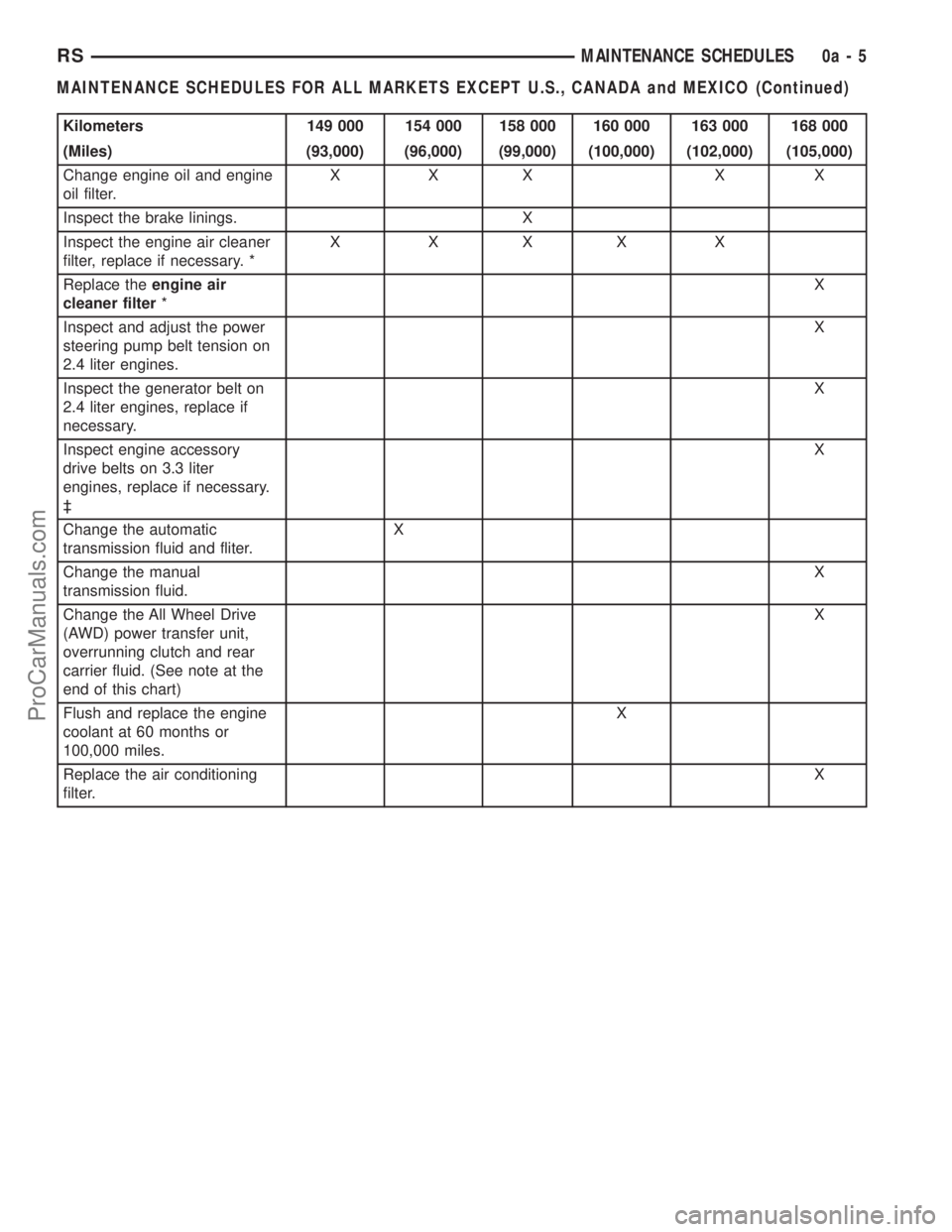
Kilometers 149 000 154 000 158 000 160 000 163 000 168 000
(Miles) (93,000) (96,000) (99,000) (100,000) (102,000) (105,000)
Change engine oil and engine
oil filter.XXX X X
Inspect the brake linings. X
Inspect the engine air cleaner
filter, replace if necessary. *X XXX X
Replace theengine air
cleaner filter*X
Inspect and adjust the power
steering pump belt tension on
2.4 liter engines.X
Inspect the generator belt on
2.4 liter engines, replace if
necessary.X
Inspect engine accessory
drive belts on 3.3 liter
engines, replace if necessary.
³X
Change the automatic
transmission fluid and fliter.X
Change the manual
transmission fluid.X
Change the All Wheel Drive
(AWD) power transfer unit,
overrunning clutch and rear
carrier fluid. (See note at the
end of this chart)X
Flush and replace the engine
coolant at 60 months or
100,000 miles.X
Replace the air conditioning
filter.X
RSMAINTENANCE SCHEDULES0a-5
MAINTENANCE SCHEDULES FOR ALL MARKETS EXCEPT U.S., CANADA and MEXICO (Continued)
ProCarManuals.com
Page 37 of 2177
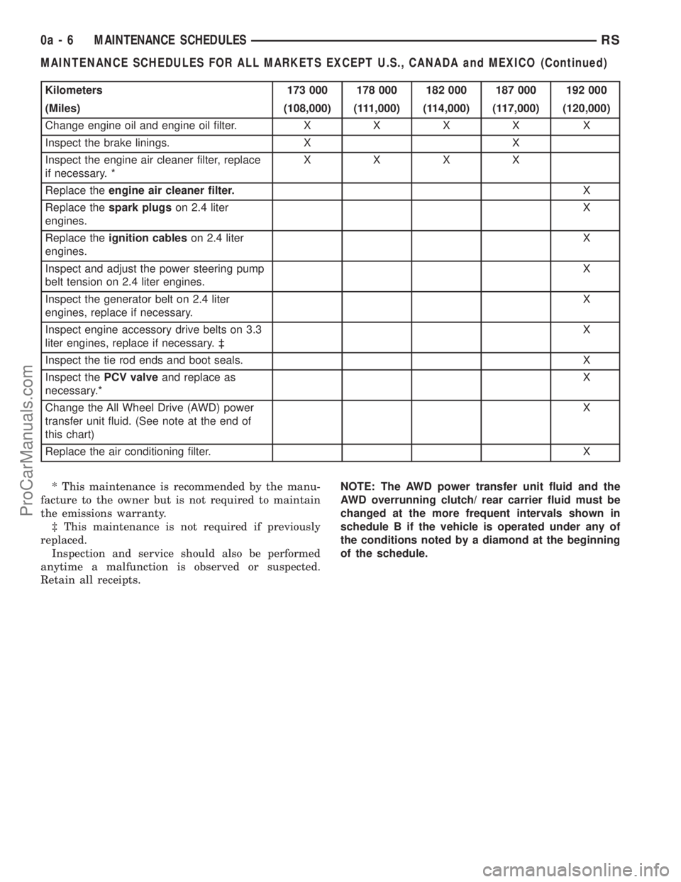
Kilometers 173 000 178 000 182 000 187 000 192 000
(Miles) (108,000) (111,000) (114,000) (117,000) (120,000)
Change engine oil and engine oil filter.XXXX X
Inspect the brake linings. X X
Inspect the engine air cleaner filter, replace
if necessary. *XXXX
Replace theengine air cleaner filter.X
Replace thespark plugson 2.4 liter
engines.X
Replace theignition cableson 2.4 liter
engines.X
Inspect and adjust the power steering pump
belt tension on 2.4 liter engines.X
Inspect the generator belt on 2.4 liter
engines, replace if necessary.X
Inspect engine accessory drive belts on 3.3
liter engines, replace if necessary. ³X
Inspect the tie rod ends and boot seals. X
Inspect thePCV valveand replace as
necessary.*X
Change the All Wheel Drive (AWD) power
transfer unit fluid. (See note at the end of
this chart)X
Replace the air conditioning filter.X
* This maintenance is recommended by the manu-
facture to the owner but is not required to maintain
the emissions warranty.
³ This maintenance is not required if previously
replaced.
Inspection and service should also be performed
anytime a malfunction is observed or suspected.
Retain all receipts.NOTE: The AWD power transfer unit fluid and the
AWD overrunning clutch/ rear carrier fluid must be
changed at the more frequent intervals shown in
schedule B if the vehicle is operated under any of
the conditions noted by a diamond at the beginning
of the schedule.
0a - 6 MAINTENANCE SCHEDULESRS
MAINTENANCE SCHEDULES FOR ALL MARKETS EXCEPT U.S., CANADA and MEXICO (Continued)
ProCarManuals.com
Page 40 of 2177
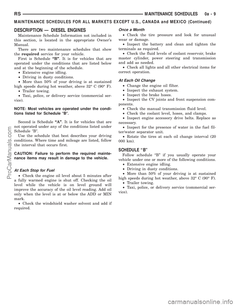
DESCRIPTION Ð DIESEL ENGINES
Maintenance Schedule Information not included in
this section, is located in the appropriate Owner's
Manual.
There are two maintenance schedules that show
therequiredservice for your vehicle.
First is ScheduleªBº. It is for vehicles that are
operated under the conditions that are listed below
and at the beginning of the schedule.
²Extensive engine idling.
²Driving in dusty conditions.
²More than 50% of your driving is at sustained
high speeds during hot weather, above 32É C (90É F).
²Trailer towing.
²Taxi, police, or delivery service (commercial ser-
vice).
NOTE: Most vehicles are operated under the condi-
tions listed for Schedule(B(.
Second is ScheduleªAº. It is for vehicles that are
not operated under any of the conditions listed under
Schedule9B9.
Use the schedule that best describes your driving
conditions. Where time and mileage are listed, follow
the interval that occurs first.
CAUTION: Failure to perform the required mainte-
nance items may result in damage to the vehicle.
At Each Stop for Fuel
²Check the engine oil level about 5 minutes after
a fully warmed engine is shut off. Checking the oil
level while the vehicle is on level ground will
improve the accuracy of the oil level reading. Add oil
only when the level is at or below the ADD or MIN
mark.
²Check the windshield washer solvent and add if
required.
Once a Month
²Check the tire pressure and look for unusual
wear or damage.
²Inspect the battery and clean and tighten the
terminals as required.
²Check the fluid levels of coolant reservoir, brake
master cylinder, power steering and transmission
and add as needed.
²Check all lights and all other electrical items for
correct operation.
At Each Oil Change
²Change the engine oil filter.
²Inspect the exhaust system.
²Inspect the brake hoses.
²Inspect the CV joints and front suspension com-
ponents.
²Check the manual transmission fluid level.
²Check the coolant level, hoses, and clamps.
²Inspect engine accessory drive belts. Replace as
necessary.
²Inspect for the presence of water in the fuel fil-
ter/water separator unit.
²Rotate the tires at each oil change interval (20
000 km).
SCHEDULE ªBº
Follow schedule ªBº if you usually operate your
vehicle under one or more of the following conditions.
²Extensive engine idling.
²Driving in dusty conditions.
²More than 50% of your driving is at sustained
high speeds during hot weather, above 32É C (90É F).
²Trailer towing.
²Taxi, police, or delivery service (commercial ser-
vice).
RSMAINTENANCE SCHEDULES0a-9
MAINTENANCE SCHEDULES FOR ALL MARKETS EXCEPT U.S., CANADA and MEXICO (Continued)
ProCarManuals.com
Page 94 of 2177
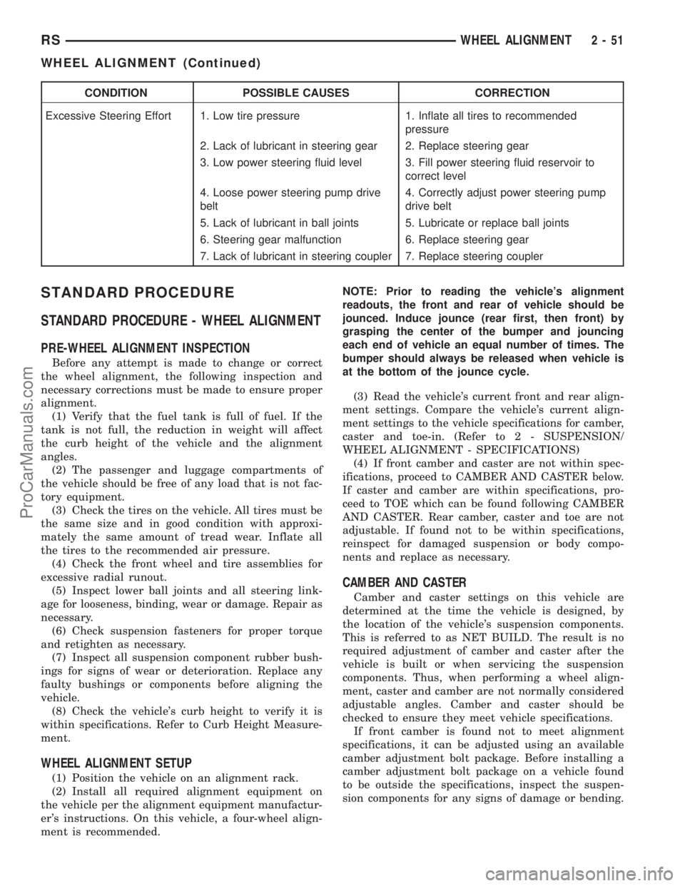
CONDITION POSSIBLE CAUSES CORRECTION
Excessive Steering Effort 1. Low tire pressure 1. Inflate all tires to recommended
pressure
2. Lack of lubricant in steering gear 2. Replace steering gear
3. Low power steering fluid level 3. Fill power steering fluid reservoir to
correct level
4. Loose power steering pump drive
belt4. Correctly adjust power steering pump
drive belt
5. Lack of lubricant in ball joints 5. Lubricate or replace ball joints
6. Steering gear malfunction 6. Replace steering gear
7. Lack of lubricant in steering coupler 7. Replace steering coupler
STANDARD PROCEDURE
STANDARD PROCEDURE - WHEEL ALIGNMENT
PRE-WHEEL ALIGNMENT INSPECTION
Before any attempt is made to change or correct
the wheel alignment, the following inspection and
necessary corrections must be made to ensure proper
alignment.
(1) Verify that the fuel tank is full of fuel. If the
tank is not full, the reduction in weight will affect
the curb height of the vehicle and the alignment
angles.
(2) The passenger and luggage compartments of
the vehicle should be free of any load that is not fac-
tory equipment.
(3) Check the tires on the vehicle. All tires must be
the same size and in good condition with approxi-
mately the same amount of tread wear. Inflate all
the tires to the recommended air pressure.
(4) Check the front wheel and tire assemblies for
excessive radial runout.
(5) Inspect lower ball joints and all steering link-
age for looseness, binding, wear or damage. Repair as
necessary.
(6) Check suspension fasteners for proper torque
and retighten as necessary.
(7) Inspect all suspension component rubber bush-
ings for signs of wear or deterioration. Replace any
faulty bushings or components before aligning the
vehicle.
(8) Check the vehicle's curb height to verify it is
within specifications. Refer to Curb Height Measure-
ment.
WHEEL ALIGNMENT SETUP
(1) Position the vehicle on an alignment rack.
(2) Install all required alignment equipment on
the vehicle per the alignment equipment manufactur-
er's instructions. On this vehicle, a four-wheel align-
ment is recommended.NOTE: Prior to reading the vehicle's alignment
readouts, the front and rear of vehicle should be
jounced. Induce jounce (rear first, then front) by
grasping the center of the bumper and jouncing
each end of vehicle an equal number of times. The
bumper should always be released when vehicle is
at the bottom of the jounce cycle.
(3) Read the vehicle's current front and rear align-
ment settings. Compare the vehicle's current align-
ment settings to the vehicle specifications for camber,
caster and toe-in. (Refer to 2 - SUSPENSION/
WHEEL ALIGNMENT - SPECIFICATIONS)
(4) If front camber and caster are not within spec-
ifications, proceed to CAMBER AND CASTER below.
If caster and camber are within specifications, pro-
ceed to TOE which can be found following CAMBER
AND CASTER. Rear camber, caster and toe are not
adjustable. If found not to be within specifications,
reinspect for damaged suspension or body compo-
nents and replace as necessary.
CAMBER AND CASTER
Camber and caster settings on this vehicle are
determined at the time the vehicle is designed, by
the location of the vehicle's suspension components.
This is referred to as NET BUILD. The result is no
required adjustment of camber and caster after the
vehicle is built or when servicing the suspension
components. Thus, when performing a wheel align-
ment, caster and camber are not normally considered
adjustable angles. Camber and caster should be
checked to ensure they meet vehicle specifications.
If front camber is found not to meet alignment
specifications, it can be adjusted using an available
camber adjustment bolt package. Before installing a
camber adjustment bolt package on a vehicle found
to be outside the specifications, inspect the suspen-
sion components for any signs of damage or bending.
RSWHEEL ALIGNMENT2-51
WHEEL ALIGNMENT (Continued)
ProCarManuals.com
Page 180 of 2177
Use only brake fluid that was stored in a tightly-
sealed container.
DO NOTuse petroleum-based fluid because seal
damage will result. Petroleum based fluids would be
items such as engine oil, transmission fluid, power
steering fluid etc.
SPECIFICATIONS
BRAKE FLUID
The brake fluid used in this vehicle must conform
to DOT 3 specifications (DOT 4 and DOT 4+ are
acceptable) and SAE J1703 standards. No other type
of brake fluid is recommended or approved for usage
in the vehicle brake system. Use only MopartBrake
Fluid or equivalent from a tightly sealed container.
CAUTION: Never use reclaimed brake fluid or fluid
from an container which has been left open. An
open container of brake fluid will absorb moisture
from the air and contaminate the fluid.
CAUTION: Never use any type of a petroleum-based
fluid in the brake hydraulic system. Use of such
type fluids will result in seal damage of the vehicle
brake hydraulic system causing a failure of the
vehicle brake system. Petroleum based fluids would
be items such as engine oil, transmission fluid,
power steering fluid, etc.
JUNCTION BLOCK
DESCRIPTION - NON-ABS JUNCTION BLOCK
A junction block is used on vehicles that are not
equipped with antilock brakes (ABS). The junction
block mounts in the same location as the integrated
control unit (ICU) does on vehicles equipped with
ABS. This allows for use of the same brake tube con-
figuration on all vehicles. The junction block is
located on the driver's side of the front suspension
cradle/crossmember below the master cylinder (Fig.
45).
It has six threaded ports to which the brake tubes
connect. Two are for the primary and secondary
brake tubes coming from the master cylinder. The
remaining four are for the chassis brake tubes going
to each brake assembly.
OPERATION - NON-ABS JUNCTION BLOCK
The junction block distributes the brake fluid com-
ing from the master cylinder primary and secondary
ports to the four chassis brake tubes leading to the
brakes at each wheel. Since the junction blockmounts in the same location as the ABS integrated
control unit (ICU), it allows for the common use of
brake tubes going to the brakes whether the vehicle
is equipped with or without ABS.
NOTE: Although the brake tubes coming from the
master cylinder to the junction block or ABS ICU
may appear to be the same, they are not. They are
unique to each brake system application.
REMOVAL - NON-ABS JUNCTION BLOCK
(1) Using a brake pedal depressor, move and lock
the brake pedal to a position past its first 1 inch of
travel. This will prevent brake fluid from draining
out of the master cylinder when the brake tubes are
removed from the junction block.
(2) Disconnect the battery negative cable.
(3) If the vehicle is equipped with speed control,
perform the following:
(a) Disconnect the battery positive cable.
(b) Remove the battery (Refer to 8 - ELECTRI-
CAL/BATTERY SYSTEM/BATTERY - REMOVAL).
(c) Disconnect the vacuum hose connector at the
tank built into the battery tray.
(d) Remove the screw securing the coolant filler
neck to the battery tray.
(e) Remove the battery tray (Refer to 8 - ELEC-
TRICAL/BATTERY SYSTEM/TRAY - REMOVAL).
(f) Remove the fasteners and move the speed
control servo off to the side, out of the way.
CAUTION: Before removing the brake tubes from
the junction block, the junction block and the brake
tubes must be thoroughly cleaned. This is required
to prevent contamination from entering the brake
hydraulic system.
(4) Remove the four chassis brake tubes from the
top of the junction block (Fig. 45).
(5) Remove the primary and secondary brake
tubes from the top of the junction block.
(6) Remove the bolts attaching the junction block
mounting bracket to the front suspension crossmem-
ber (Fig. 45), then remove the junction block.
INSTALLATION - NON-ABS JUNCTION BLOCK
(1) Install the junction block and mounting bracket
on the front suspension crossmember (Fig. 45).
Install the mounting bolts and tighten to a torque of
28 N´m (250 in. lbs.).
(2) Install the primary and secondary brake tubes
from the master cylinder in their ports. Tighten tube
nuts to a torque of 17 N´m (145 in. lbs.).Take care
not to twist tubes when tightening tube nuts.
They must be properly positioned to allow free
RSBRAKES - BASE5-33
FLUID (Continued)
ProCarManuals.com
Page 193 of 2177

INSTALLATION
INSTALLATION - LHD
(1) Position power brake booster on dash panel
using the reverse procedure of its removal (Fig. 62).
It may be necessary to push in on booster input rod
as it is guided through the dash panel.
(2) Install the four nuts mounting the booster to
the dash panel (Fig. 61). Tighten the mounting nuts
to a torque of 29 N´m (250 in. lbs.).
(3) Using lubriplate, or equivalent, coat the sur-
face of the brake pedal pin where it contacts the
booster input rod.
CAUTION: When installing the brake pedal pin on
the power brake booster input rod, do not re-use
the old retaining clip.
(4) Install booster input rod on brake pedal pin
and install a NEW retaining clip (Fig. 68).
CAUTION: Do not reuse the original brake lamp
switch. The switch can only be adjusted once. That
is during initial installation of the switch. If the
switch is not adjusted properly or has been
removed for some service, a new switch must be
installed and adjusted.
(5) Remove and replace the brake lamp switch
with a NEW switch. (Refer to 8 - ELECTRICAL/
LAMPS/LIGHTING - EXTERIOR/BRAKE LAMP
SWITCH - REMOVAL), (Refer to 8 - ELECTRICAL/
LAMPS/LIGHTING - EXTERIOR/BRAKE LAMP
SWITCH - INSTALLATION)
(6) Install the silencer panel below the steering
column.(7) Connect vacuum hose to check valve on power
brake booster.
CAUTION: The master cylinder (and its rear seal) is
used to create the seal for holding vacuum in the
vacuum booster. The vacuum seal on the master
cylinder MUST be replaced with a NEW seal when-
ever the master cylinder is removed from the vac-
uum booster.
CAUTION: When removing the vacuum seal from
the master cylinder do not use a sharp tool.
(8) Using a soft tool such as a trim stick, remove
the vacuum seal from the master cylinder mounting
flange.
(9) Install a NEW vacuum seal on rear mounting
flange of the master cylinder (Fig. 69).
(10) Position master cylinder on studs of booster,
aligning push rod on booster with master cylinder
piston.
(11) Install the two nuts mounting the master cyl-
inder to the booster (Fig. 59). Tighten both mounting
nuts to a torque of 25 N´m (225 in. lbs.).
(12) Connect wiring harness connector to brake
fluid level switch in the master cylinder fluid reser-
voir (Fig. 58).
(13) Connect primary and secondary brake tubes
to ABS ICU or non-ABS junction block (Fig. 59).
Tighten the tube nuts to 17 N´m (145 in lbs.).
(14) Install wiper module (unit). (Refer to 8 -
ELECTRICAL/WIPERS/WASHERS/WIPER MOD-
ULE - INSTALLATION)
(15) If equipped with speed control, install speed
control servo and connect wiring connector. Tighten
Fig. 67 RHD Booster Removal/Installation
1 - POWER BRAKE BOOSTER
2 - MASTER CYLINDER
Fig. 68 Retaining Pin Installed On Brake Pedal Pin
1 - BRAKE PEDAL
2 - RETAINING CLIP
3 - BOOSTER INPUT ROD
5 - 46 BRAKES - BASERS
POWER BRAKE BOOSTER (Continued)
ProCarManuals.com
Page 264 of 2177
STANDARD PROCEDURE - COOLING SYSTEM
FILLING
Remove radiator pressure cap (Fig. 6) and fill sys-
tem, using a 50/50 mix of MopartAntifreeze/Coolant,
5 Year/100,000 Mile Formula and distilled water.
Continue filling system until full.Be careful not
to spill coolant on drive belts or the generator.
For cooling system capacity, (Refer to LUBRICATION
& MAINTENANCE/FLUID CAPACITIES - SPECIFI-
CATIONS).
Fill coolant recovery/reserve container (Fig. 6) to at
least the MAX mark with 50/50 solution. It may be
necessary to add coolant to the recovery/reserve con-
tainer after three or four warm up/cool down cycles
to maintain coolant level between the MAX and MIN
mark. This will allow trapped air to be removed from
the system.
STANDARD PROCEDURE - ADDING
ADDITIONAL COOLANT
The radiator cap should not be removed.
When additional coolant is needed to maintain this
level, it should be added to the coolant recovery/re-
serve container (Fig. 6). Use only 50/50 mix of ethyl-
ene glycol type antifreeze and distilled water. For the
recommeded antifreeze/coolant type (Refer to LUBRI-
CATION & MAINTENANCE/FLUID TYPES -
DESCRIPTION).
CAUTION: Do not use well water, or suspect water
supply in cooling system. A 50/50 ethylene glycol
and distilled water mix is recommended. For the
recommeded antifreeze/coolant type (Refer to
LUBRICATION & MAINTENANCE/FLUID TYPES -
DESCRIPTION).
STANDARD PROCEDURE - COOLANT LEVEL
CHECK
NOTE: Do not remove radiator cap for routine cool-
ant level inspections.
The coolant reserve system provides a quick visual
method for determining the coolant level without
removing the radiator cap.With the engine cold
and not running,simply observe the level of the
coolant in the recovery/reserve container (Fig. 6). The
coolant level should be between the MIN and MAX
marks.
SPECIFICATIONS
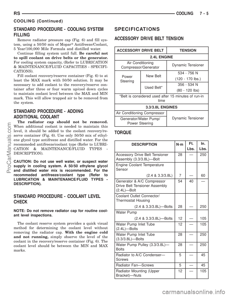
ACCESSORY DRIVE BELT TENSION
ACCESSORY DRIVE BELT TENSION
2.4L ENGINE
Air Conditioning
Compressor/GeneratorDynamic Tensioner
Power
SteeringNew Belt534 - 756 N
(120 - 170 lbs.)
Used Belt*356 - 534 N
(80 - 120 lbs)
*Belt is considered used after 15 minutes of run-in
time
3.3/3.8L ENGINES
Air Conditioning Compressor
Dynamic Tensioner
Generator/Water Pump/
Power Steering
TORQUE
DESCRIPTION N´mFt.
Lbs.In.
Lbs.
Accessory Drive Belt Tensioner
Assembly (3.3/3.8L)ÐBolt28 Ð 250
Engine Coolant Temperature
Sensor
(2.4 & 3.3/3.8L) 7 Ð 60
Generator & A/C Compressor
Drive Belt Tensioner Assembly
(2.4L)ÐBolt54 40 Ð
Coolant Outlet Connector/
Thermostat Housing
(2.4 & 3.3/3.8L)ÐBolts 28 Ð 250
Water Pump
(2.4 & 3.3/3.8L)ÐBolts 12 Ð 105
Water Pump Inlet Tube
(2.4L)ÐBolts12 Ð 105
Water Pump Inlet Tube
(3.3/3.8L)ÐBolts28 Ð 250
Water Pump Pulley (3.3/3.8L)Ð
Bolts28 Ð 250
Radiator to A/C CondenserÐ
Screws5Ð45
Radiator FanÐScrews 5 Ð 45
Radiator Mounting (Upper
Bracket)ÐNuts12 Ð 105
RSCOOLING7-5
COOLING (Continued)
ProCarManuals.com
Page 280 of 2177
(3) With heater seated, tighten center screw
securely to assure a positive seal.
(4) Install power cord plug to heater.
(5) Fill cooling system with coolant to the proper
level. (Refer to 7 - COOLING - STANDARD PROCE-
DURE)
ENGINE COOLANT
TEMPERATURE SENSOR - 2.4L
DESCRIPTION
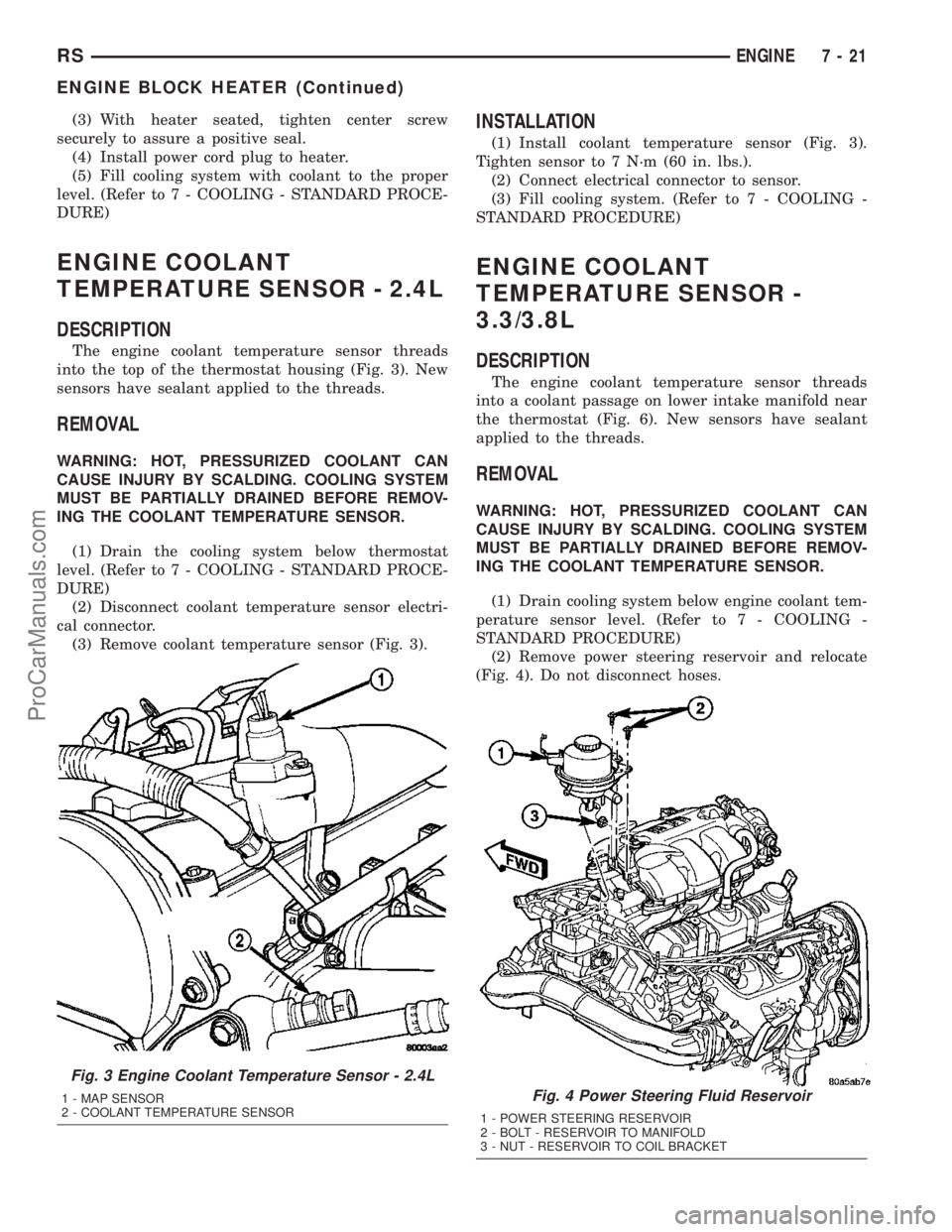
The engine coolant temperature sensor threads
into the top of the thermostat housing (Fig. 3). New
sensors have sealant applied to the threads.
REMOVAL
WARNING: HOT, PRESSURIZED COOLANT CAN
CAUSE INJURY BY SCALDING. COOLING SYSTEM
MUST BE PARTIALLY DRAINED BEFORE REMOV-
ING THE COOLANT TEMPERATURE SENSOR.
(1) Drain the cooling system below thermostat
level. (Refer to 7 - COOLING - STANDARD PROCE-
DURE)
(2) Disconnect coolant temperature sensor electri-
cal connector.
(3) Remove coolant temperature sensor (Fig. 3).
INSTALLATION
(1) Install coolant temperature sensor (Fig. 3).
Tighten sensor to 7 N´m (60 in. lbs.).
(2) Connect electrical connector to sensor.
(3) Fill cooling system. (Refer to 7 - COOLING -
STANDARD PROCEDURE)
ENGINE COOLANT
TEMPERATURE SENSOR -
3.3/3.8L
DESCRIPTION
The engine coolant temperature sensor threads
into a coolant passage on lower intake manifold near
the thermostat (Fig. 6). New sensors have sealant
applied to the threads.
REMOVAL
WARNING: HOT, PRESSURIZED COOLANT CAN
CAUSE INJURY BY SCALDING. COOLING SYSTEM
MUST BE PARTIALLY DRAINED BEFORE REMOV-
ING THE COOLANT TEMPERATURE SENSOR.
(1) Drain cooling system below engine coolant tem-
perature sensor level. (Refer to 7 - COOLING -
STANDARD PROCEDURE)
(2) Remove power steering reservoir and relocate
(Fig. 4). Do not disconnect hoses.
Fig. 3 Engine Coolant Temperature Sensor - 2.4L
1 - MAP SENSOR
2 - COOLANT TEMPERATURE SENSORFig. 4 Power Steering Fluid Reservoir
1 - POWER STEERING RESERVOIR
2 - BOLT - RESERVOIR TO MANIFOLD
3 - NUT - RESERVOIR TO COIL BRACKET
RSENGINE7-21
ENGINE BLOCK HEATER (Continued)
ProCarManuals.com
Page 1126 of 2177
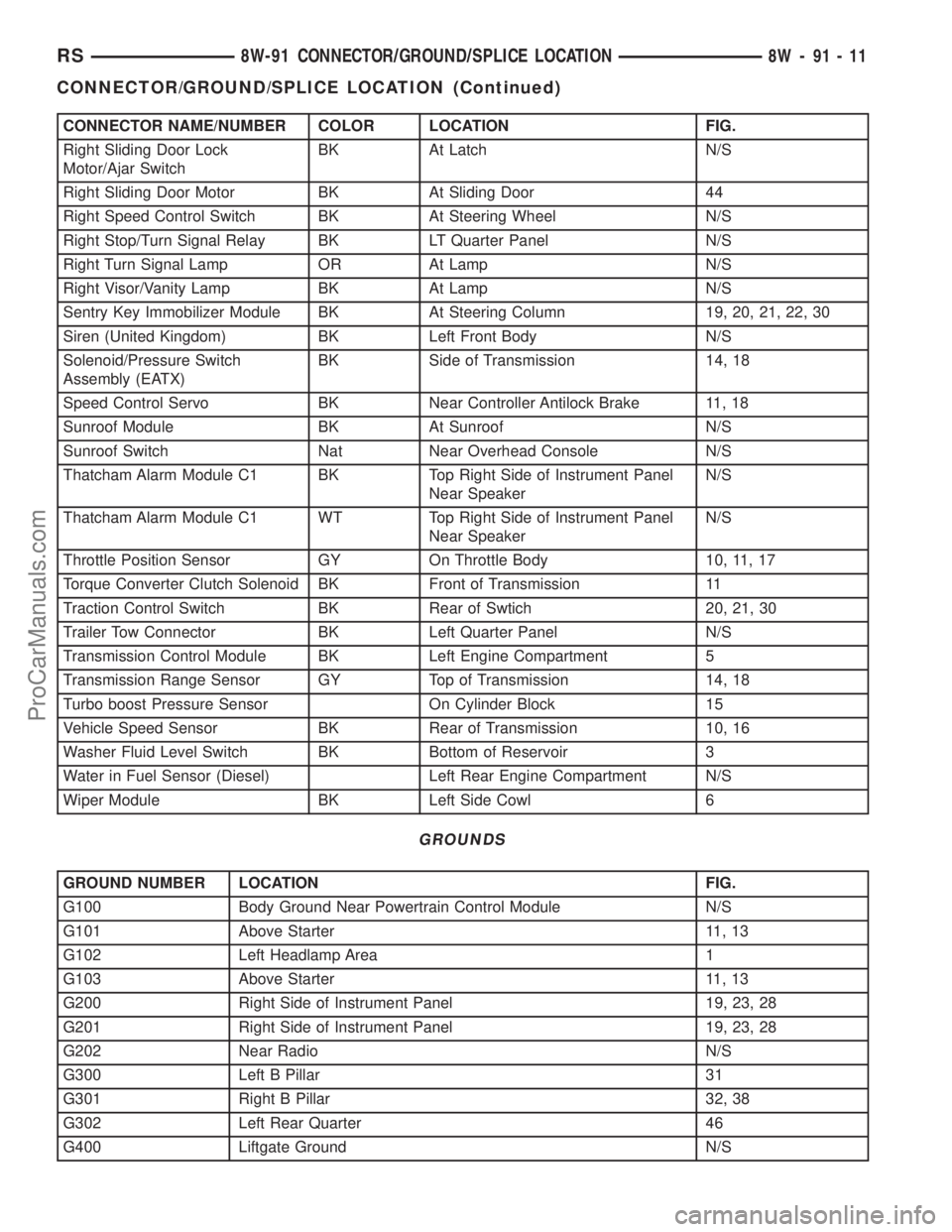
CONNECTOR NAME/NUMBER COLOR LOCATION FIG.
Right Sliding Door Lock
Motor/Ajar SwitchBK At Latch N/S
Right Sliding Door Motor BK At Sliding Door 44
Right Speed Control Switch BK At Steering Wheel N/S
Right Stop/Turn Signal Relay BK LT Quarter Panel N/S
Right Turn Signal Lamp OR At Lamp N/S
Right Visor/Vanity Lamp BK At Lamp N/S
Sentry Key Immobilizer Module BK At Steering Column 19, 20, 21, 22, 30
Siren (United Kingdom) BK Left Front Body N/S
Solenoid/Pressure Switch
Assembly (EATX)BK Side of Transmission 14, 18
Speed Control Servo BK Near Controller Antilock Brake 11, 18
Sunroof Module BK At Sunroof N/S
Sunroof Switch Nat Near Overhead Console N/S
Thatcham Alarm Module C1 BK Top Right Side of Instrument Panel
Near SpeakerN/S
Thatcham Alarm Module C1 WT Top Right Side of Instrument Panel
Near SpeakerN/S
Throttle Position Sensor GY On Throttle Body 10, 11, 17
Torque Converter Clutch Solenoid BK Front of Transmission 11
Traction Control Switch BK Rear of Swtich 20, 21, 30
Trailer Tow Connector BK Left Quarter Panel N/S
Transmission Control Module BK Left Engine Compartment 5
Transmission Range Sensor GY Top of Transmission 14, 18
Turbo boost Pressure Sensor On Cylinder Block 15
Vehicle Speed Sensor BK Rear of Transmission 10, 16
Washer Fluid Level Switch BK Bottom of Reservoir 3
Water in Fuel Sensor (Diesel) Left Rear Engine Compartment N/S
Wiper Module BK Left Side Cowl 6
GROUNDS
GROUND NUMBER LOCATION FIG.
G100 Body Ground Near Powertrain Control Module N/S
G101 Above Starter 11, 13
G102 Left Headlamp Area 1
G103 Above Starter 11, 13
G200 Right Side of Instrument Panel 19, 23, 28
G201 Right Side of Instrument Panel 19, 23, 28
G202 Near Radio N/S
G300 Left B Pillar 31
G301 Right B Pillar 32, 38
G302 Left Rear Quarter 46
G400 Liftgate Ground N/S
RS8W-91 CONNECTOR/GROUND/SPLICE LOCATION8W-91-11
CONNECTOR/GROUND/SPLICE LOCATION (Continued)
ProCarManuals.com