turn signal CHRYSLER CARAVAN 2003 Owner's Manual
[x] Cancel search | Manufacturer: CHRYSLER, Model Year: 2003, Model line: CARAVAN, Model: CHRYSLER CARAVAN 2003Pages: 2177, PDF Size: 59.81 MB
Page 435 of 2177

(2) Remove the three retaining screws (Fig. 23).
(3) Disconnect the wiring harness from the bulbs
(Fig. 24).
(4) Remove wire harness retainer from back of
headlamp unit.
(5) Remove the headlamp unit.
INSTALLATION
(1) Reconnect wire harness to the bulbs.
(2) Install wire harness retainer to headlamp unit.
(3) Install the three retaining screws.
(4) Reconnect the battery negative cable.
HEADLAMP UNIT - EXPORT
REMOVAL
(1) Disconnect and isolate the battery negative
cable.
(2) Remove the three retaining screws.
(3) Disconnect the central wiring harness connec-
tor from the headlamp unit.
(4) Remove the headlamp unit from vehicle.
INSTALLATION
(1) Connect the wiring harness to the headlamp
unit's central connector.
(2) Place headlamp unit into headlamp unit pocket
in front end.
(3) Install the three retaining screws.
(4) Connect the battery negative cable.
(5) Verify vehicle and system operation.
LICENSE LAMP
REMOVAL
(1) Disconnect and isolate the battery negative
cable.
(2) Remove two screws (Fig. 25).
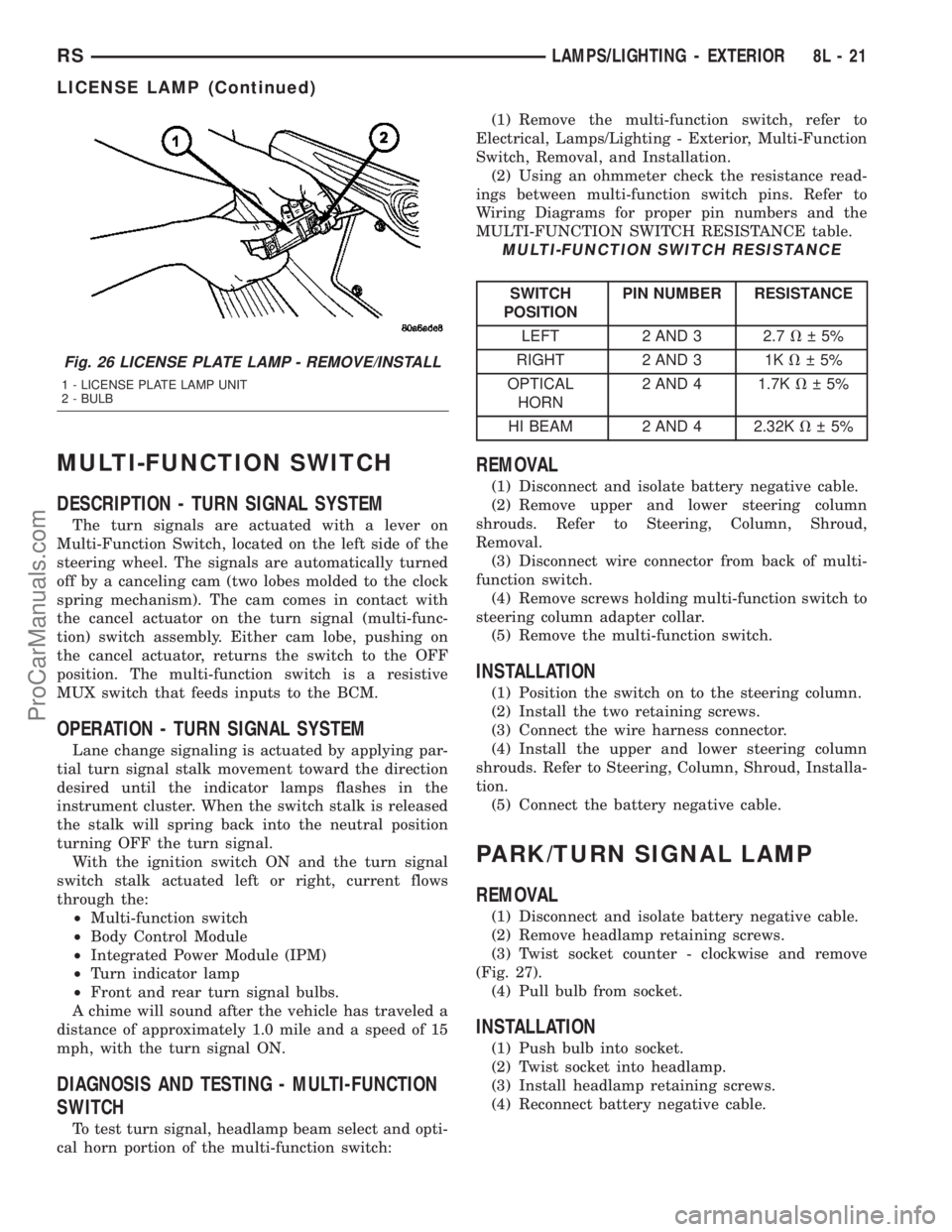
(3) Twist bulb socket and remove (Fig. 26).
(4) Pull bulb from socket.
INSTALLATION
(1) Push bulb into socket.
(2) Install socket into lamp.
(3) Install two screws.
(4) Reconnect the battery negative cable.
Fig. 23 HEADLAMP UNIT FASTENERS
1 - HEADLAMP UNIT RETAINING SCREW
2 - HEADLAMP UNIT
Fig. 24 HEADLAMP UNIT
1 - HEADLAMP UNIT
2 - HEADLAMP
3 - PARK/TURN SIGNAL LAMP
4 - WIRE HARNESS RETAINER
Fig. 25 LICENSE PLATE LAMP UNITS
1 - SCREW
2 - LICENSE PLATE LAMP
8L - 20 LAMPS/LIGHTING - EXTERIORRS
HEADLAMP UNIT (Continued)
ProCarManuals.com
Page 436 of 2177
MULTI-FUNCTION SWITCH
DESCRIPTION - TURN SIGNAL SYSTEM
The turn signals are actuated with a lever on
Multi-Function Switch, located on the left side of the
steering wheel. The signals are automatically turned
off by a canceling cam (two lobes molded to the clock
spring mechanism). The cam comes in contact with
the cancel actuator on the turn signal (multi-func-
tion) switch assembly. Either cam lobe, pushing on
the cancel actuator, returns the switch to the OFF
position. The multi-function switch is a resistive
MUX switch that feeds inputs to the BCM.
OPERATION - TURN SIGNAL SYSTEM
Lane change signaling is actuated by applying par-
tial turn signal stalk movement toward the direction
desired until the indicator lamps flashes in the
instrument cluster. When the switch stalk is released
the stalk will spring back into the neutral position
turning OFF the turn signal.
With the ignition switch ON and the turn signal
switch stalk actuated left or right, current flows
through the:
²Multi-function switch
²Body Control Module
²Integrated Power Module (IPM)
²Turn indicator lamp
²Front and rear turn signal bulbs.
A chime will sound after the vehicle has traveled a
distance of approximately 1.0 mile and a speed of 15
mph, with the turn signal ON.
DIAGNOSIS AND TESTING - MULTI-FUNCTION
SWITCH
To test turn signal, headlamp beam select and opti-
cal horn portion of the multi-function switch:(1) Remove the multi-function switch, refer to
Electrical, Lamps/Lighting - Exterior, Multi-Function
Switch, Removal, and Installation.
(2) Using an ohmmeter check the resistance read-
ings between multi-function switch pins. Refer to
Wiring Diagrams for proper pin numbers and the
MULTI-FUNCTION SWITCH RESISTANCE table.
MULTI-FUNCTION SWITCH RESISTANCE
SWITCH
POSITIONPIN NUMBER RESISTANCE
LEFT 2 AND 3 2.7V 5%
RIGHT 2 AND 3 1KV 5%
OPTICAL
HORN2 AND 4 1.7KV 5%
HI BEAM 2 AND 4 2.32KV 5%
REMOVAL
(1) Disconnect and isolate battery negative cable.
(2) Remove upper and lower steering column
shrouds. Refer to Steering, Column, Shroud,
Removal.
(3) Disconnect wire connector from back of multi-
function switch.
(4) Remove screws holding multi-function switch to
steering column adapter collar.
(5) Remove the multi-function switch.
INSTALLATION
(1) Position the switch on to the steering column.
(2) Install the two retaining screws.
(3) Connect the wire harness connector.
(4) Install the upper and lower steering column
shrouds. Refer to Steering, Column, Shroud, Installa-
tion.
(5) Connect the battery negative cable.
PARK/TURN SIGNAL LAMP
REMOVAL
(1) Disconnect and isolate battery negative cable.
(2) Remove headlamp retaining screws.
(3) Twist socket counter - clockwise and remove
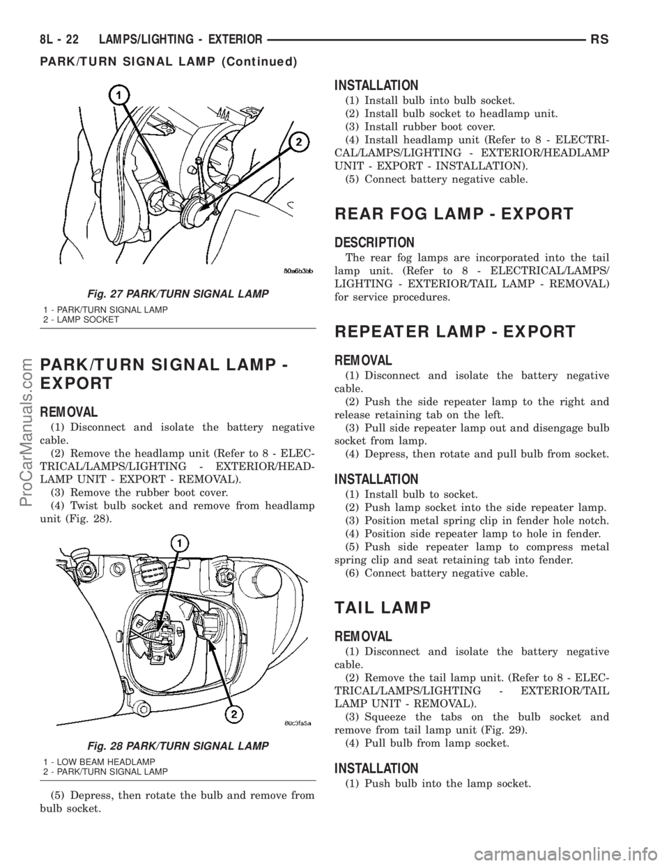
(Fig. 27).
(4) Pull bulb from socket.
INSTALLATION
(1) Push bulb into socket.
(2) Twist socket into headlamp.
(3) Install headlamp retaining screws.
(4) Reconnect battery negative cable.
Fig. 26 LICENSE PLATE LAMP - REMOVE/INSTALL
1 - LICENSE PLATE LAMP UNIT
2 - BULB
RSLAMPS/LIGHTING - EXTERIOR8L-21
LICENSE LAMP (Continued)
ProCarManuals.com
Page 437 of 2177
PARK/TURN SIGNAL LAMP -
EXPORT
REMOVAL
(1) Disconnect and isolate the battery negative
cable.
(2) Remove the headlamp unit (Refer to 8 - ELEC-
TRICAL/LAMPS/LIGHTING - EXTERIOR/HEAD-
LAMP UNIT - EXPORT - REMOVAL).
(3) Remove the rubber boot cover.
(4) Twist bulb socket and remove from headlamp
unit (Fig. 28).
(5) Depress, then rotate the bulb and remove from
bulb socket.
INSTALLATION
(1) Install bulb into bulb socket.
(2) Install bulb socket to headlamp unit.
(3) Install rubber boot cover.
(4) Install headlamp unit (Refer to 8 - ELECTRI-
CAL/LAMPS/LIGHTING - EXTERIOR/HEADLAMP
UNIT - EXPORT - INSTALLATION).
(5) Connect battery negative cable.
REAR FOG LAMP - EXPORT
DESCRIPTION
The rear fog lamps are incorporated into the tail
lamp unit. (Refer to 8 - ELECTRICAL/LAMPS/
LIGHTING - EXTERIOR/TAIL LAMP - REMOVAL)
for service procedures.
REPEATER LAMP - EXPORT
REMOVAL
(1) Disconnect and isolate the battery negative
cable.
(2) Push the side repeater lamp to the right and
release retaining tab on the left.
(3) Pull side repeater lamp out and disengage bulb
socket from lamp.
(4) Depress, then rotate and pull bulb from socket.
INSTALLATION
(1) Install bulb to socket.
(2) Push lamp socket into the side repeater lamp.
(3) Position metal spring clip in fender hole notch.
(4) Position side repeater lamp to hole in fender.
(5) Push side repeater lamp to compress metal
spring clip and seat retaining tab into fender.
(6) Connect battery negative cable.
TAIL LAMP
REMOVAL
(1) Disconnect and isolate the battery negative
cable.
(2) Remove the tail lamp unit. (Refer to 8 - ELEC-
TRICAL/LAMPS/LIGHTING - EXTERIOR/TAIL
LAMP UNIT - REMOVAL).
(3) Squeeze the tabs on the bulb socket and
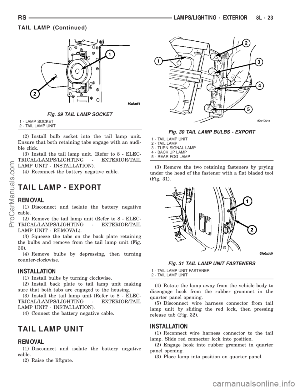
remove from tail lamp unit (Fig. 29).
(4) Pull bulb from lamp socket.
INSTALLATION
(1) Push bulb into the lamp socket.
Fig. 27 PARK/TURN SIGNAL LAMP
1 - PARK/TURN SIGNAL LAMP
2 - LAMP SOCKET
Fig. 28 PARK/TURN SIGNAL LAMP
1 - LOW BEAM HEADLAMP
2 - PARK/TURN SIGNAL LAMP
8L - 22 LAMPS/LIGHTING - EXTERIORRS
PARK/TURN SIGNAL LAMP (Continued)
ProCarManuals.com
Page 438 of 2177
(2) Install bulb socket into the tail lamp unit.
Ensure that both retaining tabs engage with an audi-
ble click.
(3) Install the tail lamp unit. (Refer to 8 - ELEC-
TRICAL/LAMPS/LIGHTING - EXTERIOR/TAIL
LAMP UNIT - INSTALLATION).
(4) Reconnect the battery negative cable.
TAIL LAMP - EXPORT
REMOVAL
(1) Disconnect and isolate the battery negative
cable.
(2) Remove the tail lamp unit (Refer to 8 - ELEC-
TRICAL/LAMPS/LIGHTING - EXTERIOR/TAIL
LAMP UNIT - REMOVAL).
(3) Squeeze the tabs on the back plate retaining
the bulbs and remove from the tail lamp unit (Fig.
30).
(4) Remove bulbs by depressing, then turning
counter-clockwise.
INSTALLATION
(1) Install bulbs by turning clockwise.
(2) Install back plate to tail lamp unit making
sure that both tabs are engaged to the housing.
(3) Install the tail lamp unit (Refer to 8 - ELEC-
TRICAL/LAMPS/LIGHTING - EXTERIOR/TAIL
LAMP UNIT - INSTALLATION).
(4) Connect the battery negative cable.
TAIL LAMP UNIT
REMOVAL
(1) Disconnect and isolate the battery negative
cable.
(2) Raise the liftgate.(3) Remove the two retaining fasteners by prying
under the head of the fastener with a flat bladed tool
(Fig. 31).
(4) Rotate the lamp away from the vehicle body to
disengage hook from the rubber grommet in the
quarter panel opening.
(5) Disconnect wire harness connector from tail
lamp unit by sliding the red lock, then pressing
release tab (Fig. 32).
INSTALLATION
(1) Reconnect wire harness connector to the tail
lamp. Slide red connector lock into position.
(2) Engage hook into rubber grommet in quarter
panel opening.
(3) Place lamp into position on quarter panel.
Fig. 29 TAIL LAMP SOCKET
1 - LAMP SOCKET
2 - TAIL LAMP UNIT
Fig. 30 TAIL LAMP BULBS - EXPORT
1 - TAIL LAMP UNIT
2 - TAIL LAMP
3 - TURN SIGNAL LAMP
4 - BACK UP LAMP
5 - REAR FOG LAMP
Fig. 31 TAIL LAMP UNIT FASTENERS
1 - TAIL LAMP UNIT FASTENER
2 - TAIL LAMP UNIT
RSLAMPS/LIGHTING - EXTERIOR8L-23
TAIL LAMP (Continued)
ProCarManuals.com
Page 440 of 2177

LAMPS/LIGHTING - INTERIOR
TABLE OF CONTENTS
page page
LAMPS/LIGHTING - INTERIOR
SPECIFICATIONS
INTERIOR LAMPS.....................25
CENTER CONSOLE LAMP SWITCH
REMOVAL.............................26
INSTALLATION.........................26
CLUSTER ILLUMINATION LAMPS
REMOVAL.............................26
INSTALLATION.........................26
COURTESY LAMP
REMOVAL.............................26
INSTALLATION.........................26
DOME/CARGO LAMP
REMOVAL.............................26INSTALLATION.........................26
GLOVE BOX LAMP SWITCH
REMOVAL.............................26
INSTALLATION.........................26
LIFTGATE LAMP
REMOVAL.............................27
INSTALLATION.........................27
READING LAMP
REMOVAL.............................27
INSTALLATION.........................28
VANITY LAMP
REMOVAL.............................28
INSTALLATION.........................28
LAMPS/LIGHTING - INTERIOR
SPECIFICATIONS
INTERIOR LAMPS
BULB APPLICATION TABLE
LAMP BULB
ABS LED
AIRBAG LED
ALARM SET PC74
AUTOSTICK VFD*
BRAKE SYSTEM
WARNINGLED
CONSOLE 194
CRUISE INDICATOR VFD*
DOME/RAIL LAMPS 578
DOOR AJAR INDICATOR LED
DOOR COURTESY
LAMP578
FRONT DOOR
COURTESY567
GLOVE BOX 194
HIGH BEAM INDICATOR
(BASE CLUSTER)LED
HIGH BEAM INDICATOR PC74
LAMP BULB
CLUSTER
ILLUMINATIONPC74
LIFTGATE 578
LIFTGATE AJAR LED
LOW FUEL INDICATOR LED
LOW WASHER FLUID
INDICATORLED
MIL (BASE CLUSTER) LED
MIL PC74
OIL INDICATOR (BASE
CLUSTER)LED
OIL INDICATOR PC74
OVERHEAD CONSOLE
READINGPC579
OVERDRIVE OFF
INDICATORVFD*
READING 578
SEAT BELT INDICATOR LED
TEMPERATURE
INDICATORLED
TRAC OFF INDICATOR VFD*
TURN SIGNAL
INDICATOR (BASE
CLUSTER)LED
TURN SIGNAL
INDICATORPC74
VISOR VANITY 6501966
RSLAMPS/LIGHTING - INTERIOR8L-25
ProCarManuals.com
Page 451 of 2177
PROGRAMMABLE FEATURES
NOTE: Tire pressure monitoring (TPM) system infor-
mation is not covered in this section of the service
manual. Refer to the tires/wheels section of this
manual for detailed tire pressure monitoring system
information.
²LANGUAGE?- The options include English,
Francaise, Deutsch, Italiana, or Espanol. The default
is English. All EVIC display nomenclature, including
the trip computer functions, warning messages and
the programmable features appear in the selected
language.
²DISPLAY U.S. OR METRIC?- The options
include U.S. and M. The default is U.S. This feature
toggles the trip computer temperature, fuel economy
and odometer display readings between U.S. and
metric units of measure. It also changes the odome-
ter display in the instrument cluster.
²SERVICE INTV. =- The options include from
1000 to 12000 kilometers in 1000 kilometer incre-
ments (2000 to 7500 miles in 500 mile increments).
The default is 12000 kilometers (7500 miles). The
selected distance becomes the interval at which the
Perform Service warning message will be displayed
by the EVIC. If a new distance is selected, a second
programmable feature appears,RESET SERVICE
DISTANCE?- The options include No and Yes. The
default is Yes. When Yes is selected, the accumulated
distance since the last previous Perform Service
warning message will be reset to zero because the
service interval has been changed. When No is
selected, the distance until the next Perform Service
warning message is reduced by the accumulated dis-
tance since the last previous message.
²USE FACTORY SETTINGS?- The options
include Yes and No. The default is Yes. When yes is
selected all the programmable features will return to
there defaults and the rest of the programmable fea-
tures will not be displayed. If No is selected the rest
of the programmable features will be displayed at
there default values. This feature will automatically
return to the Yes default under two conditions. First,
if no programmable features are changed from there
defaults. Second, if all the programmable features
equal there defaults.
²AUTO DOOR LOCKS?- The options include
Yes and No. The default is Yes. When Yes is selected,
all doors and the liftgate lock automatically when
vehicle speed reaches 25 kilometers-per-hour (15
miles-per-hour). If YES is selected, a second program-
mable feature appears,AUTO UNLOCK ON EXIT?
- The options again include Yes and No. The default
is No. When Yes is selected, following each Auto Door
Lock event all doors and the liftgate will automati-
cally unlock when the driver door is opened, if thevehicle is stopped and the transmission gear selector
is in Park or Neutral. The Auto Door Unlock event
will only occur once following each Auto Door Lock
event.
²REMOTE UNLOCK- The options include
Driver Door 1st and All Doors. The default is Driver
Door 1st. When Diver Door 1st is selected, only the
driver door unlocks when the Unlock button of the
Remote Keyless Entry (RKE) transmitter is
depressed once. The Unlock button of the RKE trans-
mitter must be depressed twice to unlock all doors.
When All Doors is selected, all doors unlock when the
Unlock button of the RKE transmitter is depressed
once.
²REMOTE LINKED TO MEMORY?- This pro-
grammable feature only applies to vehicles equipped
with the optional memory / heated system. The
options include Yes and No. The default is No. When
Yes is selected, the memory system will recall the
Driver 1 or Driver 2 memory settings assigned to the
RKE transmitter being used to unlock the vehicle.
When No is selected, the memory system will only
recall memory settings when the Driver 1 or Driver 2
push buttons of the memory switch on the driver side
front door trim panel are depressed.
²SOUND HORN ON LOCK?- The options
include Yes and No. The default is No. When Yes is
selected, a short horn chirp will provide an audible
confirmation when the RKE receiver recognizes a
valid Lock signal from an RKE transmitter. When No
is selected, no horn chirp will occur with the RKE
Lock event. This feature may be selected indepen-
dent of theFLASH LIGHTS WITH LOCKS?pro-
grammable feature.
²FLASH LIGHTS WITH LOCKS?- The options
include Yes and No. The default is Yes. When Yes is
selected, a single flash of the hazard warning lamps
will provide an optical confirmation when the RKE
receiver recognizes a valid Lock signal from an RKE
transmitter, and two flashes of the same lamps will
occur when the RKE receiver recognizes a valid
Unlock signal from an RKE transmitter. When No is
selected, no lamp flash will occur with the RKE Lock
or Unlock event. This feature may be selected inde-
pendent of theSOUND HORN ON LOCK?pro-
grammable feature.
²HEADLAMP DELAY =- The options include
Off, 30 Sec, 60 Sec, and 90 Sec. The default is 90 Sec.
When a time interval is selected, the headlamps will
remain on for that length of time when the head-
lamps are turned off after the ignition is turned off,
or if the Auto mode is selected on vehicles with the
Auto Headlamps option. When Off is selected, the
headlamp delay feature is disabled.
²HEADLAMPS ON WITH WIPERS?- This pro-
grammable feature only applies to vehicles equipped
8M - 8 MESSAGE SYSTEMSRS
ELECTRONIC VEHICLE INFO CENTER (Continued)
ProCarManuals.com
Page 454 of 2177

Transmitter and the EVIC module are inoperative,
refer toElectronic Vehicle Information Center
Diagnosis and Testingin this group for further
diagnosis. For complete circuit diagrams, refer to
Wiring Diagrams. (Fig. 5) as described below:
(1) Turn the Radio Frequency (RF) Detector ON. A
ªchirpº will sound and the green power LED will
light. If the green LED does not light, replace the
battery.
(2) Hold the RF detector within one inch of the
TRAINED universal transmitter and press any of the
transmitters buttons.
(3) The red signal detection LEDs will light and
the tool will beep if a radio signal is detected. Repeat
this test three times.
STANDARD PROCEDURE
STANDARD PROCEDURE - SETTING
TRANSMITTER CODES
(1) Turn off the engine.
(2) Erase the codes by pressing the two outside
buttons. Release the buttons when the display con-
firms the operation (about 20 seconds).
(3) Choose one of the three buttons to train. Place
the hand-held transmitter within one inch of the uni-
versal transmitter and push the buttons on both
transmitters.(4) Release both buttons. Your universal transmit-
ter is now ªtrainedº. To train the other buttons,
repeat Step 3 and Step 4. Be sure to keep your hand-
held transmitter in case you need to retrain the uni-
versal transmitter.
STANDARD PROCEDURE - ERASING
TRANSMITTER CODES
To erase the universal transmitter codes, simply
hold down the two outside buttons until the display
confirms the operation.
NOTE: Individual channels cannot be erased. Eras-
ing the transmitter codes will erase ALL pro-
grammed codes.
REMOVAL
(1) For universal transmitter removal and installa-
tion procedure, (Refer to 8 - ELECTRICAL/OVER-
HEAD CONSOLE/COMPASS/MINI-TRIP
COMPUTER - REMOVAL and INSTALLATION).
AMBIENT TEMP SENSOR
DESCRIPTION
Ambient air temperature is monitored by the over-
head console through ambient temperature messages
received from the Front Control Module (FCM) over
the Programmable Communications Interface (PCI)
J1850 data bus circuit. The FCM receives a hard
wired input from the ambient temperature sensor.
The ambient temperature sensor is a variable resis-
tor mounted to a bracket that is secured with a screw
to the right side of the headlamp mounting module
grille opening, behind the radiator grille and in front
of the engine compartment.
For more information on the Front Control Module
refer to the Electronic Control Modules section of this
manual. For complete circuit diagrams, refer to the
appropriate wiring information. The ambient temper-
ature sensor cannot be adjusted or repaired and, if
faulty or damaged, it must be replaced.
OPERATION
The ambient temperature sensor is a variable
resistor that operates on a five-volt reference signal
sent to it by the Front Control Module. The resis-
tance in the sensor changes as temperature changes,
changing the temperature sensor signal circuit volt-
age to the Front Control Module. Based upon the
resistance in the sensor, the Front Control Module
senses a specific voltage on the temperature sensor
signal circuit, which it is programmed to correspond
to a specific temperature. The Front Control Module
Fig. 5 RADIO FREQUENCY DETECTOR
1 - SIGNAL DETECTION LED'S
2 - POWER LED
3 - ON/OFF SWITCH
4 - 9V BATTERY
RSMESSAGE SYSTEMS8M-11
UNIVERSAL TRANSMITTER (Continued)
ProCarManuals.com
Page 455 of 2177

then sends the proper ambient temperature mes-
sages to the EVIC, CMTC over the PCI J1850 data
bus.
The thermometer function is supported by the
ambient temperature sensor, a wiring circuit, the
Front Control Module, the Programmable Communi-
cations Interface (PCI) data bus, and a portion of the
Electronics module. If any portion of the ambient
temperature sensor circuit fails, the Front Control
Module will self-diagnose the circuit.
The ambient temperature sensor circuit can also be
diagnosed by referring toDiagnosis and Testing -
Ambient Temperature Sensor, and Diagnosis
and Testing - Ambient Temperature Sensor Cir-
cuit. If the temperature sensor and circuit are con-
firmed to be OK, but the temperature display is
inoperative or incorrect, refer toDiagnosis and
Testing - Overhead Consolein this group. For
complete circuit diagrams, refer to the appropriate
wiring information.
DIAGNOSIS AND TESTING
DIAGNOSIS AND TESTING - AMBIENT
TEMPERATURE SENSOR
(1) Turn the ignition switch to the Off position.
Disconnect and isolate the battery negative cable.
Disconnect the ambient temperature sensor wire har-
ness connector.
(2) Measure the resistance of the ambient temper-
ature sensor. At ±40É C (±40É F), the sensor resis-
tance is 336.6 kilohms. At 60É C (140É F), the sensor
resistance is 2.49 kilohms. The sensor resistance
should read between these two values. If OK, refer to
Diagnosis and Testing - Ambient Temperature
Sensor Circuitin this group. If not OK, replace the
faulty ambient temperature sensor.
DIAGNOSIS AND TESTING - AMBIENT
TEMPERATURE SENSOR CIRCUIT
(1) Turn the ignition switch to the Off position.
Disconnect and isolate the battery negative cable.
Disconnect the ambient temperature sensor wire har-
ness connector and the Front Control Module wire
harness connector.(2) Connect a jumper wire between the two termi-
nals in the body half of the ambient temperature sen-
sor wire harness connector.
(3) Check for continuity between the sensor return
circuit and the ambient temperature sensor signal
circuit cavities of the Front Control Module wire har-
ness connector. There should be continuity. If OK, go
to Step 4. If not OK, repair the open sensor return
circuit or ambient temperature sensor signal circuit
to the ambient temperature sensor as required.
(4) Remove the jumper wire from the body half of
the ambient temperature sensor wire harness con-
nector. Check for continuity between the sensor
return circuit cavity of the Front Control Module
wire harness connector and a good ground. There
should be no continuity. If OK, go to Step 5. If not
OK, repair the shorted sensor return circuit as
required.
(5) Check for continuity between the ambient tem-
perature sensor signal circuit cavity of the Front
Control Module wire harness connector and a good
ground. There should be no continuity. If OK, refer to
Diagnosis and Testing - Overhead Consolein
this group. If not OK, repair the shorted ambient
temperature sensor signal circuit as required.
REMOVAL
(1) Disconnect and isolate the battery negative
cable.
(2) From behind front bumper fascia, remove
screw holding sensor to radiator closure panel.
(3) Disconnect the sensor electrical connector.
Depress the connector retaining tab and pull the con-
nector straight off the ambient temperature sensor.
(4) Remove sensor from vehicle.
INSTALLATION
(1) Position the sensor in the vehicle and connect
the sensor electrical connector.
(2) From behind the front bumper fascia, install
the screw holding sensor to radiator closure panel.
(3) Connect the battery negative cable.
8M - 12 MESSAGE SYSTEMSRS
AMBIENT TEMP SENSOR (Continued)
ProCarManuals.com
Page 466 of 2177
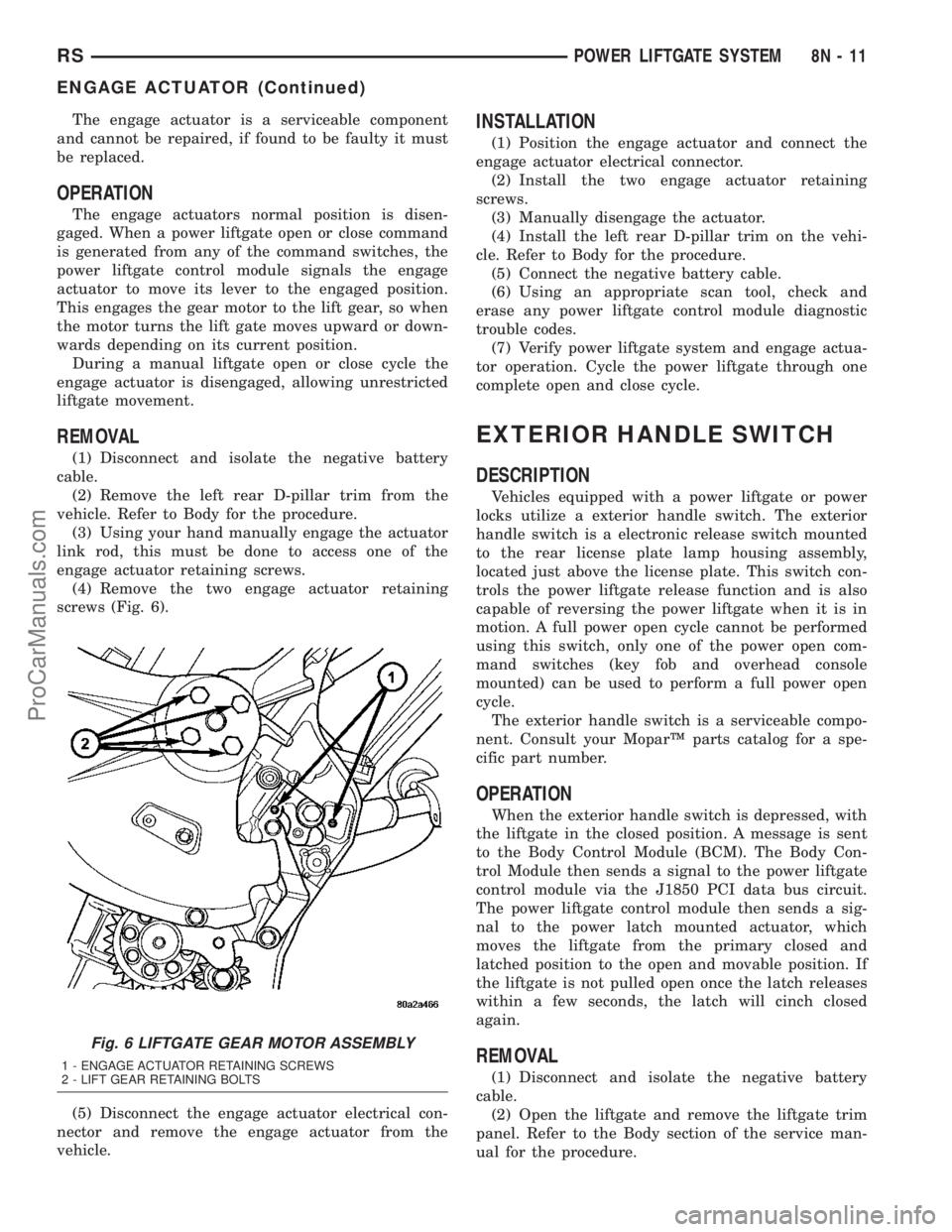
The engage actuator is a serviceable component
and cannot be repaired, if found to be faulty it must
be replaced.
OPERATION
The engage actuators normal position is disen-
gaged. When a power liftgate open or close command
is generated from any of the command switches, the
power liftgate control module signals the engage
actuator to move its lever to the engaged position.
This engages the gear motor to the lift gear, so when
the motor turns the lift gate moves upward or down-
wards depending on its current position.
During a manual liftgate open or close cycle the
engage actuator is disengaged, allowing unrestricted
liftgate movement.
REMOVAL
(1) Disconnect and isolate the negative battery
cable.
(2) Remove the left rear D-pillar trim from the
vehicle. Refer to Body for the procedure.
(3) Using your hand manually engage the actuator
link rod, this must be done to access one of the
engage actuator retaining screws.
(4) Remove the two engage actuator retaining
screws (Fig. 6).
(5) Disconnect the engage actuator electrical con-
nector and remove the engage actuator from the
vehicle.
INSTALLATION
(1) Position the engage actuator and connect the
engage actuator electrical connector.
(2) Install the two engage actuator retaining
screws.
(3) Manually disengage the actuator.
(4) Install the left rear D-pillar trim on the vehi-
cle. Refer to Body for the procedure.
(5) Connect the negative battery cable.
(6) Using an appropriate scan tool, check and
erase any power liftgate control module diagnostic
trouble codes.
(7) Verify power liftgate system and engage actua-
tor operation. Cycle the power liftgate through one
complete open and close cycle.
EXTERIOR HANDLE SWITCH
DESCRIPTION
Vehicles equipped with a power liftgate or power
locks utilize a exterior handle switch. The exterior
handle switch is a electronic release switch mounted
to the rear license plate lamp housing assembly,
located just above the license plate. This switch con-
trols the power liftgate release function and is also
capable of reversing the power liftgate when it is in
motion. A full power open cycle cannot be performed
using this switch, only one of the power open com-
mand switches (key fob and overhead console
mounted) can be used to perform a full power open
cycle.
The exterior handle switch is a serviceable compo-
nent. Consult your MoparŸ parts catalog for a spe-
cific part number.
OPERATION
When the exterior handle switch is depressed, with
the liftgate in the closed position. A message is sent
to the Body Control Module (BCM). The Body Con-
trol Module then sends a signal to the power liftgate
control module via the J1850 PCI data bus circuit.
The power liftgate control module then sends a sig-
nal to the power latch mounted actuator, which
moves the liftgate from the primary closed and
latched position to the open and movable position. If
the liftgate is not pulled open once the latch releases
within a few seconds, the latch will cinch closed
again.
REMOVAL
(1) Disconnect and isolate the negative battery
cable.
(2) Open the liftgate and remove the liftgate trim
panel. Refer to the Body section of the service man-
ual for the procedure.
Fig. 6 LIFTGATE GEAR MOTOR ASSEMBLY
1 - ENGAGE ACTUATOR RETAINING SCREWS
2 - LIFT GEAR RETAINING BOLTS
RSPOWER LIFTGATE SYSTEM8N-11
ENGAGE ACTUATOR (Continued)
ProCarManuals.com
Page 494 of 2177

REMOTE KEYLESS ENTRY SYSTEM
The key fob transmitter (Fig. 1) has six buttons.
Three of them, LOCK, UNLOCK, and PANIC, are
used to actuate parts of, and program the Remote
Keyless Entry (RKE) system via the customer pro-
gramming mode. It is not necessary to use the
PANIC button with the DRB IIItscan tool mode of
programming.
OPERATION
POWER DOOR LOCK SYSTEM
The Body Control Module (BCM) locks or unlocks
the doors when an actuation input signal from a door
lock switch or Remote Keyless Entry Module (RKE)
is received. The BCM turns on the output drivers
and provides a voltage level to the door lock motor
for a specified time. The BCM locks the doors auto-
matically when the vehicle is driven beyond the
speed of 25.7 Km/h (16 mph). The rolling door lock
feature can be disabled if desired. All doors and lift-
gate can be locked or unlocked using mechanical but-
ton or key cylinder methods (Liftgate cylinder does
not lock/unlock vehicle. It only unlocks the liftgate).
AUTOMATIC DOOR LOCKS
The BCM is equipped with a disable feature to
stop the speed sensitive automatic door locks from
functioning. The DISABLE feature can be switchedON or OFF as desired. When the system is DIS-
ABLED the door locks will operate normally, but will
not lock automatically when the vehicle is rolling.
When the door locks are ENABLED the door locks
will automatically lock when the vehicle is moving at
about 25.7 Km/h (16 mph). All doors are closed, the
PCM has set the ªOK TO LOCKº bit, and doors were
not previously locked.
DOOR LOCK INHIBIT
If the key is in the ignition, in any position, and
either front door is ajar, all power door lock function-
ing shall be disabled when activating either door lock
switch. Also, if the Vehicle Theft Alarm (VTA) is
armed, the door lock switch ªUNLOCKº feature will
be disabled until the vehicle is disarmed. Pressing
the RKE lock/unlock button under these conditions
will result in a normal lock/unlock activation.
After the key is removed from the Ignition Switch,
or the doors are closed, the power door locks will
operate normally.
CENTRAL LOCKING
If equipped with Vehicle Theft Security System
(VTSS), all the doors can be locked with the key by
using any of the door lock cylinders. Turning the key
to the LOCK position will lock all the doors.
When the driver door key cylinder switch is
detected active, the BCM will activate the illumi-
nated entry feature and the individual front doors
will become mechanically unlocked. To central unlock
all doors, a second transition from OFF to UNLOCK
has to occur within 2 seconds of the first complete
UNLOCK cycle.
To central unlock the driver door, turn the key to
the rear of the vehicle. This indicates an unlock sig-
nal to the BCM. When key cylinder switch is
detected as active, the BCM will activate the illumi-
nated entry feature. The individual doors will become
mechanically unlocked.
To central lock the vehicle, the driver door lock cyl-
inder is turned toward the front of the vehicle. When
a lock input from either key cylinder is detected as
active, the BCM will cancel the illuminated entry
feature and perform the central lock operation.
DOOR LOCK CIRCUIT PROTECTION
The BCM controls the door lock output drivers. If
the door lock switch is actuated continuously for
more than one second the BCM will turn the output
driver OFF (the BCM would consider the switch
stuck). The lock motors are protected with Positive
Temperature Coefficient (PTC) device that prevents
motor burn out.
Fig. 1 KEY FOB
1 - LEFT SLIDING DOOR BUTTON
2 - RIGHT SLIDING DOOR BUTTON
3 - LIFTGATE SWITCH
RSPOWER LOCKS8N-39
POWER LOCKS (Continued)
ProCarManuals.com