stop start CHRYSLER CARAVAN 2003 Owner's Guide
[x] Cancel search | Manufacturer: CHRYSLER, Model Year: 2003, Model line: CARAVAN, Model: CHRYSLER CARAVAN 2003Pages: 2177, PDF Size: 59.81 MB
Page 2086 of 2177
(4) Open both the suction and discharge valves,
then open the charge valve to allow the heated
refrigerant to flow into the system.
(5) When the transfer of refrigerant has stopped,
close both the suction and discharge valves.
(6) If all of the refrigerant charge did not transfer
from the dispensing device, open all of the windows
in the vehicle and set the heater-air conditioner con-
trols so that the compressor is engaged and the
blower motor is operating at its lowest speed setting.
Run the engine at a steady high idle (about 1400
rpm). If the compressor will not engage, test the com-
pressor clutch control circuit and repair as required.
(7) Open the suction valve to allow the remaining
refrigerant to transfer to the refrigerant system.
WARNING: TAKE CARE NOT TO OPEN THE DIS-
CHARGE (HIGH PRESSURE) VALVE AT THIS TIME.
(8) Close the suction valve and test the system
performance. (Refer to 24 - HEATING & AIR CON-
DITIONING - STANDARD PROCEDURE - A/C PER-
FORMANCE TEST).
(9) Disconnect the charging station and manifold
gauge set from the refrigerant system service ports.
(10) Reinstall the caps onto the refrigerant system
service ports.
(11) Run the HVAC Control Cooldown test to ver-
ify proper operation(Refer to 24 - HEATING & AIR
CONDITIONING - DIAGNOSIS AND TESTING).
STANDARD PROCEDURE - REFRIGERANT
SYSTEM EVACUATE
WARNING: REFER TO THE APPLICABLE WARN-
INGS AND CAUTIONS FOR THIS SYSTEM BEFORE
PERFORMING THE FOLLOWING OPERATION.
(Refer to 24 - HEATING & AIR CONDITIONING/
PLUMBING - FRONT - WARNING - A/C PLUMBING)
and (Refer to 24 - HEATING & AIR CONDITIONING/
PLUMBING - FRONT - CAUTION - A/C PLUMBING).
If the refrigerant system has been open to the
atmosphere, it must be evacuated before the system
can be charged. If moisture and air enters the system
and becomes mixed with the refrigerant, the com-
pressor head pressure will rise above acceptable
operating levels. This will reduce the performance of
the air conditioner and damage the compressor.
Evacuating the refrigerant system will remove the
air and boil the moisture out of the system at near
room temperature. A R-134a refrigerant recovery/re-
cycling/charging station that meets SAE Standard
J2210 must be used to evacuate the refrigerant sys-
tem. See the operating instructions supplied by the
equipment manufacturer for proper care and use ofthis equipment. To evacuate the refrigerant system,
use the following procedure:
NOTE: When connecting the service equipment
couplings to the refrigerant system service ports,
be certain that the valve of each coupling is fully
closed. This will reduce the amount of effort
required to make the connection.
(1) Remove the caps from the refrigerant system
service ports and attach a manifold gauge set and a
R-134a refrigerant recovery/recycling/charging sta-
tion that meets SAE Standard J2210 to the refriger-
ant system.
(2) Open both the suction and discharge valves
and start the charging station vacuum pump.
(3) When the suction gauge has read 88 kPa (26
in. Hg.) vacuum or greater for 45 minutes, close both
the suction and discharge valves and turn off the
vacuum pump. If the refrigerant system fails to
reach the specified vacuum, the system has a leak
that must be corrected. (Refer to 24 - HEATING &
AIR CONDITIONING/PLUMBING - FRONT/RE-
FRIGERANT - STANDARD PROCEDURE -
REFRIGERANT SYSTEM LEAKS).
(4) If the refrigerant system maintains the speci-
fied vacuum for thirty minutes, restart the vacuum
pump, open both the suction and discharge valves,
and evacuate the system for an additional ten min-
utes.
(5) Close both the suction and discharge valves,
and turn off the charging station vacuum pump.
(6) The refrigerant system is now ready to be
charged with R-134a refrigerant. (Refer to 24 -
HEATING & AIR CONDITIONING/PLUMBING -
FRONT/REFRIGERANT - STANDARD PROCE-
DURE - REFRIGERANT SYSTEM CHARGE).
STANDARD PROCEDURE - REFRIGERANT
RECOVERY
WARNING: REFER TO THE APPLICABLE WARN-
INGS AND CAUTIONS FOR THIS SYSTEM BEFORE
PERFORMING THE FOLLOWING OPERATION.
(Refer to 24 - HEATING & AIR CONDITIONING/
PLUMBING - FRONT - WARNING - A/C PLUMBING)
and (Refer to 24 - HEATING & AIR CONDITIONING/
PLUMBING - FRONT - CAUTION - A/C PLUMBING).
A R-134a refrigerant recovery/recycling/charging
station that meets SAE Standard J2210 must be
used to recover the refrigerant from an R-134a refrig-
erant system, whenever the refrigerant system must
be opened for service. See the operating instructions
supplied by the equipment manufacturer for the
proper care and use of this equipment.
RSPLUMBING - FRONT24-89
REFRIGERANT (Continued)
ProCarManuals.com
Page 2125 of 2177
ORVR
OPERATION
The emission control principle used in the ORVR
system is that the fuel flowing into the filler tube
(appx. 1º I.D.) creates an aspiration effect which
draws air into the fill tube (Fig. 9). During refueling,
the fuel tank is vented to the vapor canister to cap-
ture escaping vapors. With air flowing into the filler
tube, there are no fuel vapors escaping to the atmo-
sphere. Once the refueling vapors are captured by
the canister, the vehicle's computer controlled purge
system draws vapor out of the canister for the engine
to burn. The vapors flow is metered by the purge
solenoid so that there is no or minimal impact on
driveability or tailpipe emissions.
As fuel starts to flow through the fill tube, it opens
the normally closed check valve and enters the fuel
tank. Vapor or air is expelled from the tank through
the control valve to the vapor canister. Vapor is
absorbed in the canister until vapor flow in the lines
stops, either following shut-off or by having the fuel
level in the tank rise high enough to close the control
valve. The control valve(Refer to 14 - FUEL SYS-
TEM/FUEL DELIVERY/FUEL TANK - OPERATION)
contains a float that rises to seal the large diameter
vent path to the canister. At this point in the fueling
of the vehicle, the tank pressure increases, the check
valve closes (preventing tank fuel from spitting back
at the operator), and fuel then rises up the filler tube
to shut-off the dispensing nozzle.
If the engine is shut-off while the On-Board diag-
nostics test is running, low level tank pressure can
be trapped in the fuel tank and fuel can not be added
to the tank until the pressure is relieved. This is due
to the leak detection pump closing the vapor outlet
from the top of the tank and the one-way check valve
not allowing the tank to vent through the fill tube to
atmosphere. Therefore, when fuel is added, it will
back-up in the fill tube and shut off the dispensing
nozzle. The pressure can be eliminated in two ways:
1. Vehicle purge must be activated and for a long
enough period to eliminate the pressure. 2. Removing
the fuel cap and allowing enough time for the system
to vent thru the recirulation tube.
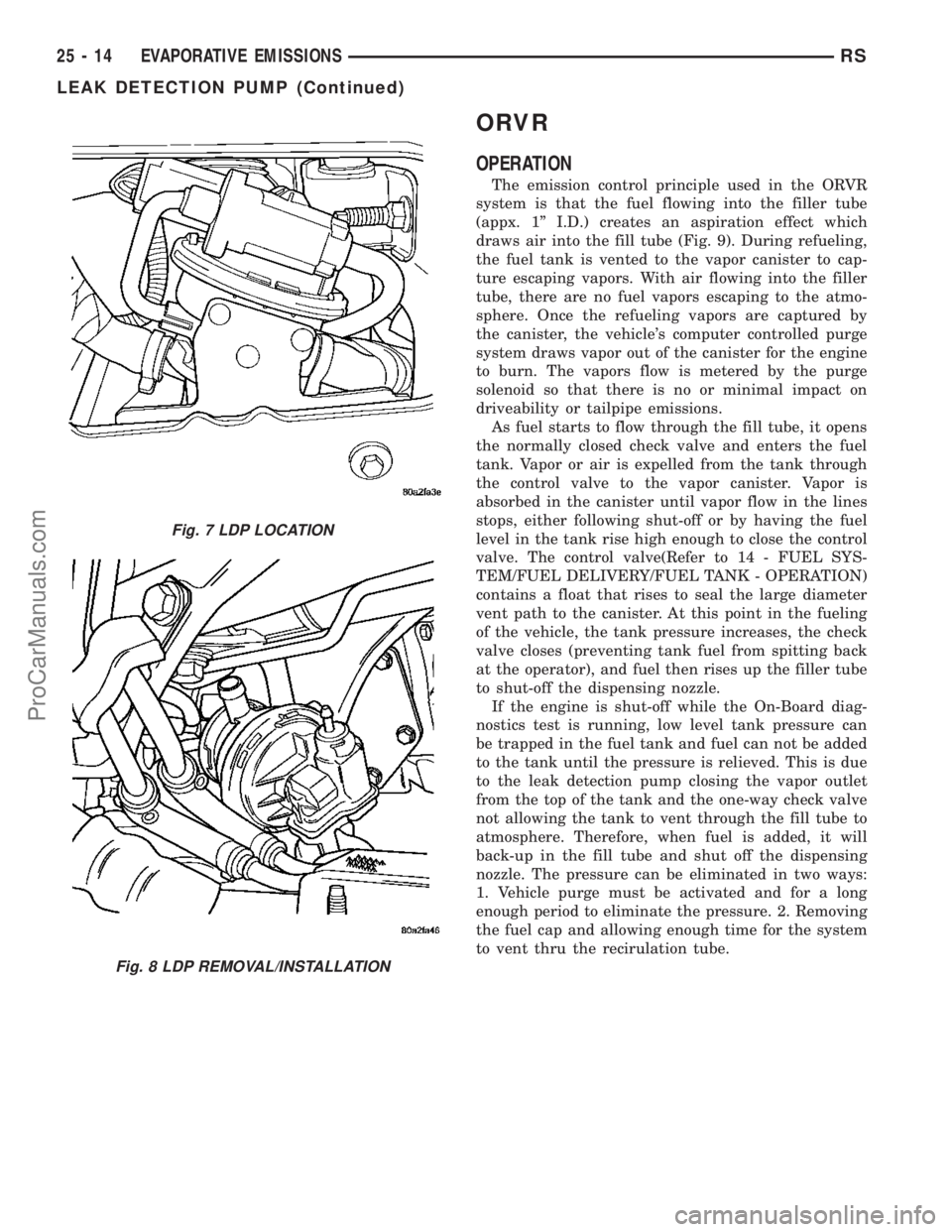
Fig. 7 LDP LOCATION
Fig. 8 LDP REMOVAL/INSTALLATION
25 - 14 EVAPORATIVE EMISSIONSRS
LEAK DETECTION PUMP (Continued)
ProCarManuals.com
Page 2137 of 2177
Alternate Good Trip
Alternate Good Trips are used in place of Global
Good Trips for Comprehensive Components and
Major Monitors. If the Task Manager cannot run a
Global Good Trip because a component fault is stop-
ping the monitor from running, it will attempt to
count an Alternate Good Trip.
The Task Manager counts an Alternate Good Trip
for Comprehensive components when the following
conditions are met:
²Two minutes of engine run time, idle or driving
²No other faults occur
The Task Manager counts an Alternate Good Trip
for a Major Monitor when the monitor runs and
passes. Only the Major Monitor that failed needs to
pass to count an Alternate Good Trip.
Warm-Up Cycles
Once the MIL has been extinguished by the Good
Trip Counter, the PCM automatically switches to a
Warm-Up Cycle Counter that can be viewed on the
DRBIIIt. Warm-Up Cycles are used to erase DTCs
and Freeze Frames. Forty Warm-Up cycles must
occur in order for the PCM to self-erase a DTC and
Freeze Frame. A Warm-Up Cycle is defined as fol-
lows:
²Engine coolant temperature must start below
and rise above 160É F
²Engine coolant temperature must rise by 40É F
²No further faults occur
Freeze Frame Data Storage
Once a failure occurs, the Task Manager records
several engine operating conditions and stores it in a
Freeze Frame. The Freeze Frame is considered one
frame of information taken by an on-board data
recorder. When a fault occurs, the PCM stores the
input data from various sensors so that technicians
can determine under what vehicle operating condi-
tions the failure occurred.
The data stored in Freeze Frame is usually
recorded when a system fails the first time for two
trip faults. Freeze Frame data will only be overwrit-
ten by a different fault with a higher priority.
CAUTION: Erasing DTCs, either with the DRBIIIT;or
by disconnecting the battery, also clears all Freeze
Frame data.
Similar Conditions Window
The Similar Conditions Window displays informa-
tion about engine operation during a monitor. Abso-
lute MAP (engine load) and Engine RPM are stored
in this window when a failure occurs. There are two
different Similar conditions Windows: Fuel System
and Misfire.FUEL SYSTEM
²Fuel System Similar Conditions WindowÐ
An indicator that 'Absolute MAP When Fuel Sys Fail'
and 'RPM When Fuel Sys Failed' are all in the same
range when the failure occurred. Indicated by switch-
ing from 'NO' to 'YES'.
²Absolute MAP When Fuel Sys FailÐ The
stored MAP reading at the time of failure. Informs
the user at what engine load the failure occurred.
²Absolute MAPÐ A live reading of engine load
to aid the user in accessing the Similar Conditions
Window.
²RPM When Fuel Sys FailÐ The stored RPM
reading at the time of failure. Informs the user at
what engine RPM the failure occurred.
²Engine RPMÐ A live reading of engine RPM
to aid the user in accessing the Similar Conditions
Window.
²Adaptive Memory FactorÐ The PCM utilizes
both Short Term Compensation and Long Term Adap-
tive to calculate the Adaptive Memory Factor for
total fuel correction.
²Upstream O2S VoltsÐ A live reading of the
Oxygen Sensor to indicate its performance. For
example, stuck lean, stuck rich, etc.
²SCW Time in Window (Similar Conditions
Window Time in Window)Ð A timer used by the
PCM that indicates that, after all Similar Conditions
have been met, if there has been enough good engine
running time in the SCW without failure detected.
This timer is used to increment a Good Trip.
²Fuel System Good Trip CounterÐATrip
Counter used to turn OFF the MIL for Fuel System
DTCs. To increment a Fuel System Good Trip, the
engine must be in the Similar Conditions Window,
Adaptive Memory Factor must be less than cali-
brated threshold and the Adaptive Memory Factor
must stay below that threshold for a calibrated
amount of time.
²Test Done This TripÐ Indicates that the
monitor has already been run and completed during
the current trip.
MISFIRE
²Same Misfire Warm-Up StateÐ Indicates if
the misfire occurred when the engine was warmed up
(above 160É F).
²In Similar Misfire WindowÐ An indicator
that 'Absolute MAP When Misfire Occurred' and
'RPM When Misfire Occurred' are all in the same
range when the failure occurred. Indicated by switch-
ing from 'NO' to 'YES'.
²Absolute MAP When Misfire OccurredÐ
The stored MAP reading at the time of failure.
Informs the user at what engine load the failure
occurred.
25 - 26 ON-BOARD DIAGNOSTICSRS
TASK MANAGER (Continued)
ProCarManuals.com
Page 2156 of 2177
INPUT - OPERATION, DATA BUS
COMMUNICATION RECEIVE - PCM.......8E-15
INPUT - OPERATION, IGNITION SENSE -
PCM...............................8E-15
INPUT - OPERATION, SENSOR RETURN -
PCM...............................8E-15
INPUT - OPERATION, SPEED SENSOR . . . 21-240
INPUT - REMOVAL, SPEED SENSOR.....21-240
INPUT CLUTCH ASSEMBLY - ASSEMBLY . 21-216
INPUT CLUTCH ASSEMBLY -
DISASSEMBLY......................21-208
INPUT FLANGE SEAL - INSTALLATION.....3-45
INPUT FLANGE SEAL - REMOVAL.........3-44
INPUT SHAFT - ASSEMBLY.............21-96
INPUT SHAFT - DESCRIPTION..........21-93
INPUT SHAFT - DISASSEMBLY..........21-93
INPUT SHAFT COVER SEAL -
INSTALLATION.......................21-14
INPUT SHAFT COVER SEAL - REMOVAL . . . 21-13
INPUT SHAFT END SEAL -
INSTALLATION.......................21-16
INPUT SHAFT END SEAL - REMOVAL.....21-15
INPUT SHAFT SEAL - INSTALLATION.....21-18
INPUT SHAFT SEAL - REMOVAL.........21-17
INSIDE HANDLE CABLE - INSTALLATION . . 23-37
INSIDE HANDLE CABLE - REMOVAL......23-37
INSIDE LATCH HANDLE - INSTALLATION . . 23-33
INSIDE LATCH HANDLE - REMOVAL......23-33
INSPECT, INSPECTION...............21-114
INSTRUMENT CLUSTER - DESCRIPTION . . . 8J-1
INSTRUMENT CLUSTER - OPERATION.....8J-1
INSTRUMENT PANEL - INSTALLATION,
LOWER............................23-68
INSTRUMENT PANEL - REMOVAL,
LOWER............................23-68
INSTRUMENT PANEL ANTENNA CABLE -
INSTALLATION.......................8A-9
INSTRUMENT PANEL ANTENNA CABLE -
REMOVAL...........................8A-8
INSTRUMENT PANEL ASSEMBLY -
INSTALLATION.......................23-65
INSTRUMENT PANEL ASSEMBLY -
REMOVAL..........................23-64
INSTRUMENT PANEL CENTER BEZEL -
INSTALLATION.......................23-67
INSTRUMENT PANEL CENTER BEZEL -
REMOVAL..........................23-67
INSTRUMENT PANEL END CAP -
INSTALLATION.......................23-67
INSTRUMENT PANEL END CAP -
REMOVAL..........................23-67
INSTRUMENT PANEL OUTLET -
INSTALLATION.......................24-42
INSTRUMENT PANEL OUTLET -
REMOVAL..........................24-42
INSTRUMENT PANEL TOP COVER -
INSTALLATION.......................23-67
INSTRUMENT PANEL TOP COVER -
REMOVAL..........................23-67
INSTRUMENT PANEL TOP PAD
ASSEMBLY - INSTALLATION............23-70
INSTRUMENT PANEL TOP PAD
ASSEMBLY - REMOVAL................23-70
INTAKE MANIFOLD - DESCRIPTION . . 9-144,9-58
INTAKE MANIFOLD - INSTALLATION,
LOWER............................9-149
INTAKE MANIFOLD - INSTALLATION,
UPPER.............................9-147
INTAKE MANIFOLD - LOWER -
CLEANING..........................9-148
INTAKE MANIFOLD - LOWER -
INSPECTION....................9-148,9-60
INTAKE MANIFOLD - LOWER -
INSTALLATION........................9-60
INTAKE MANIFOLD - LOWER - REMOVAL . . 9-60
INTAKE MANIFOLD - REMOVAL, LOWER . . 9-148
INTAKE MANIFOLD - REMOVAL, UPPER . . . 9-145
INTAKE MANIFOLD - UPPER -
INSPECTION.........................9-59
INTAKE MANIFOLD - UPPER -
INSTALLATION........................9-59
INTAKE MANIFOLD - UPPER - REMOVAL
. . . 9-58
INTAKE MANIFOLD LEAKS - DIAGNOSIS
AND TESTING
...................9-145,9-58
INTAKE MANIFOLD VACUUM PORT
REPAIR - STANDARD PROCEDURE
.......9-145
INTAKE PIPE - INSTALLATION, AIR
......24-113
INTAKE PIPE - REMOVAL, AIR
.........24-112INTAKE/EXHAUST VALVES & SEATS -
CLEANING......................9-105,9-32
INTAKE/EXHAUST VALVES & SEATS -
DESCRIPTION...................9-104,9-32
INTAKE/EXHAUST VALVES & SEATS -
INSPECTION........................9-105
INTAKE/EXHAUST VALVES & SEATS -
INSTALLATION.......................9-106
INTAKE/EXHAUST VALVES & SEATS -
OPERATION.........................9-104
INTAKE/EXHAUST VALVES & SEATS -
REMOVAL..........................9-105
INTEGRAL ANTENNA - EXPORT -
DESCRIPTION, QUARTER GLASS.........8A-9
INTEGRAL ANTENNA - EXPORT -
DIAGNOSIS AND TESTING, QUARTER
GLASS..............................8A-9
INTEGRAL ANTENNA - EXPORT -
OPERATION, QUARTER GLASS...........8A-9
INTEGRATED POWER MODULE -
DESCRIPTION.....................8W-97-3
INTEGRATED POWER MODULE -
INSTALLATION....................8W-97-4
INTEGRATED POWER MODULE -
OPERATION.......................8W-97-3
INTEGRATED POWER MODULE -
REMOVAL........................8W-97-4
INTERACTIVE SPEED CONTROL (4
SPEED EATX ONLY) - OPERATION........8P-2
INTERFACE (PCI) BUS, OPERATION -
PROGRAMMABLE COMMUNICATIONS....14-21
INTERIOR LAMPS, SPECIFICATIONS......8L-25
INTERLOCK - DESCRIPTION, IGNITION....19-17
INTERLOCK SOLENOID - DESCRIPTION,
SHIFT.............................21-233
INTERLOCK SOLENOID - DIAGNOSIS
AND TESTING, BRAKE/TRANSMISSION
SHIFT.............................21-235
INTERLOCK SOLENOID - INSTALLATION,
SHIFT.............................21-236
INTERLOCK SOLENOID - OPERATION,
SHIFT.............................21-233
INTERLOCK SOLENOID - REMOVAL,
SHIFT.............................21-235
INTERLOCK SWITCH - INSTALLATION,
CLUTCH PEDAL.......................6-14
INTERLOCK SWITCH - REMOVAL,
CLUTCH PEDAL.......................6-13
INTERMEDIATE SHAFT - ASSEMBLY.....21-107
INTERMEDIATE SHAFT - DESCRIPTION . . 21-100
INTERMEDIATE SHAFT - DISASSEMBLY . . 21-100
INTERNATIONAL SYMBOLS -
DESCRIPTION......................Intro.-5
INTERNATIONAL SYMBOLS -
DESCRIPTION.........................0-1
INTRODUCTION - DIAGNOSIS AND
TESTING, ENGINE DIAGNOSIS........9-3,9-76
IOD FUSE - DESCRIPTION...........8W-97-4
IOD FUSE - INSTALLATION...........8W-97-5
IOD FUSE - OPERATION.............8W-97-5
IOD FUSE - REMOVAL..............8W-97-5
JOINT - DESCRIPTION, LOWER BALL......2-10
JOINT - DIAGNOSIS AND TESTING,
LOWER BALL........................2-10
JOINT - OPERATION, LOWER BALL.......2-10
JOINT MOLDING - INSTALLATION, ROOF . . 23-57
JOINT MOLDING - REMOVAL, ROOF......23-57
JOINT SEAL BOOT - INSTALLATION,
BALL
...............................2-11
JOINT SEAL BOOT - REMOVAL, BALL
.....2-11
JOUNCE BUMPER - DESCRIPTION
........2-35
JOUNCE BUMPER - OPERATION
..........2-35
JUMP STARTING - STANDARD
PROCEDURE
.........................0-15
JUNCTION BLOCK - DESCRIPTION,
NON-ABS
............................5-33
JUNCTION BLOCK - INSTALLATION,
NON-ABS
............................5-33
JUNCTION BLOCK - OPERATION,
NON-ABS
............................5-33
JUNCTION BLOCK - REMOVAL, NON-ABS
. . 5-33
KEY - DESCRIPTION, TRANSPONDER
.....8Q-3
KEY - OPERATION, TRANSPONDER
.......8Q-3
KEY IMMOBILIZER MODULE -
DESCRIPTION, SENTRY
................8E-18
KEY IMMOBILIZER MODULE -
INSTALLATION, SENTRY
...............8E-19KEY IMMOBILIZER MODULE -
OPERATION, SENTRY.................8E-18
KEY IMMOBILIZER MODULE - REMOVAL,
SENTRY............................8E-18
KEY IMMOBILIZER SYSTEM -
DIAGNOSIS AND TESTING, SENTRY.......8Q-3
KEYLESS ENTRY MODULE -
DESCRIPTION, REMOTE...............8N-43
KEYLESS ENTRY MODULE - DIAGNOSIS
AND TESTING, REMOTE...............8N-43
KEYLESS ENTRY MODULE -
INSTALLATION, REMOTE..............8N-44
KEYLESS ENTRY MODULE - OPERATION,
REMOTE...........................8N-43
KEYLESS ENTRY MODULE - REMOVAL,
REMOTE...........................8N-44
KEYLESS ENTRY TRANSMITTER -
DIAGNOSIS AND TESTING.............8N-42
KEY/LOCK CYLINDER - DESCRIPTION....19-20
KEY/LOCK CYLINDER - INSTALLATION....19-20
KEY/LOCK CYLINDER - OPERATION......19-20
KEY/LOCK CYLINDER - REMOVAL.......19-20
KNOB - INSTALLATION, GEARSHIFT......21-87
KNOB - INSTALLATION, SEAT BELT
HEIGHT ADJUSTER...................8O-13
KNOB - REMOVAL, GEARSHIFT..........21-87
KNOB - REMOVAL, SEAT BELT HEIGHT
ADJUSTER.........................8O-13
KNOCK SENSOR - DESCRIPTION..........8I-8
KNOCK SENSOR - OPERATION...........8I-8
KNUCKLE - DESCRIPTION.................2-6
KNUCKLE - INSPECTION, STEERING........2-9
KNUCKLE - INSTALLATION, STEERING......2-9
KNUCKLE - OPERATION.................2-7
KNUCKLE - REMOVAL, STEERING.........2-7
LABEL - DESCRIPTION, E-MARK......Intro.-11
LABEL - DESCRIPTION, VECI.........Intro.-11
LABEL - DESCRIPTION, VEHICLE
EMISSION CONTROL INFORMATION.......25-1
LABEL - DESCRIPTION, VEHICLE SAFETY
CERTIFICATION....................Intro.-11
LAMP - DESCRIPTION, VTSS/SKIS
INDICATOR..........................8Q-5
LAMP - DIAGNOSIS AND TESTING,
FRONT FOG..........................8L-7
LAMP - EXPORT - DESCRIPTION, REAR
FOG ...............................8L-22
LAMP - EXPORT - INSTALLATION,
FRONT FOG..........................8L-9
LAMP - EXPORT - INSTALLATION,
FRONT POSITION....................8L-10
LAMP - EXPORT - INSTALLATION,
PARK/TURN SIGNAL..................8L-22
LAMP - EXPORT - INSTALLATION,
REPEATER..........................8L-22
LAMP - EXPORT - INSTALLATION, TAIL . . . 8L-23
LAMP - EXPORT - REMOVAL, FRONT
FOG ................................8L-9
LAMP - EXPORT - REMOVAL, FRONT
POSITION..........................8L-10
LAMP - EXPORT - REMOVAL,
PARK/TURN SIGNAL..................8L-22
LAMP - EXPORT - REMOVAL, REPEATER . . 8L-22
LAMP - EXPORT - REMOVAL, TAIL.......8L-23
LAMP - INSTALLATION, CENTER HIGH
MOUNTED STOP......................8L-6
LAMP - INSTALLATION, COURTESY......8L-26
LAMP - INSTALLATION, DOME/CARGO....8L-26
LAMP - INSTALLATION, FRONT FOG.......8L-9
LAMP - INSTALLATION, LICENSE........8L-20
LAMP - INSTALLATION, LIFTGATE.......8L-27
LAMP - INSTALLATION, PARK/TURN
SIGNAL............................8L-21
LAMP - INSTALLATION, READING........8L-28
LAMP - INSTALLATION, TAIL...........8L-22
LAMP - INSTALLATION, VANITY.........8L-28
LAMP - OPERATION, VTSS/SKIS
INDICATOR..........................8Q-5
LAMP - REMOVAL, CENTER HIGH
MOUNTED STOP......................8L-6
LAMP - REMOVAL, COURTESY..........8L-26
LAMP - REMOVAL, DOME/CARGO.......8L-26
LAMP - REMOVAL, FRONT FOG..........8L-9
LAMP - REMOVAL, LICENSE
............8L-20
LAMP - REMOVAL, LIFTGATE
...........8L-27
LAMP - REMOVAL, PARK/TURN SIGNAL
. . 8L-21
LAMP - REMOVAL, READING
...........8L-27
LAMP - REMOVAL, TAIL
...............8L-22
RSINDEX17
Description Group-Page Description Group-Page Description Group-Page
ProCarManuals.com
Page 2170 of 2177
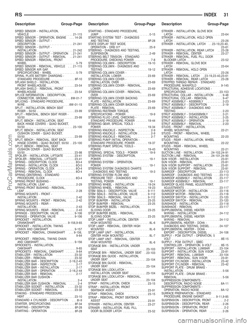
SPEED SENSOR - INSTALLATION,
VEHICLE..........................21-115
SPEED SENSOR - OPERATION, ENGINE . . . 14-26
SPEED SENSOR - OUTPUT -
DESCRIPTION......................21-241
SPEED SENSOR - OUTPUT -
INSTALLATION......................21-242
SPEED SENSOR - OUTPUT - OPERATION . 21-241
SPEED SENSOR - OUTPUT - REMOVAL . . 21-241
SPEED SENSOR - REMOVAL, FRONT
WHEEL.............................5-79
SPEED SENSOR - REMOVAL, VEHICLE . . . 21-115
SPEED SENSOR AIR GAP,
SPECIFICATIONS - WHEEL..............5-79
SPIRAL PLATE BATTERY CHARGING -
STANDARD PROCEDURE...............8F-10
SPLASH SHIELD - INSTALLATION,
FRONT WHEELHOUSE.................23-54
SPLASH SHIELD - REMOVAL, FRONT
WHEELHOUSE.......................23-54
SPLICE INFORMATION - DESCRIPTION,
CONNECTOR, GROUND..............8W-01-7
SPLICING - STANDARD PROCEDURE,
WIRE...........................8W-01-15
SPLIT - INSTALLATION, BENCH SEAT
RISER - 50/50.......................23-99
SPLIT - REMOVAL, BENCH SEAT RISER -
50/50..............................23-99
SPLIT, BENCH - INSTALLATION, SEAT
BACK HINGE COVERS - QUAD BUCKET,
50/50.............................23-100
SPLIT, BENCH - INSTALLATION, SEAT
CUSHION COVER - QUAD BUCKET,
50/50..............................23-99
SPLIT, BENCH - REMOVAL, SEAT BACK
HINGE COVERS - QUAD BUCKET, 50/50 . . 23-100
SPLIT, BENCH - REMOVAL, SEAT
CUSHION COVER - QUAD BUCKET,
50/50..............................23-98
SPOILER - INSTALLATION, LIFTGATE.....23-41
SPOILER - REMOVAL, LIFTGATE.........23-41
SPRING - DESCRIPTION, CLOCK.........8O-4
SPRING - INSTALLATION, CLOCK.........8O-5
SPRING - OPERATION, CLOCK...........8O-4
SPRING - REMOVAL, CLOCK............8O-4
SPRING CENTERING - STANDARD
PROCEDURE, CLOCK..................8O-4
SPRING FRONT BUSHING -
INSTALLATION, LEAF...................2-29
SPRING FRONT BUSHING - REMOVAL,
LEAF...............................2-28
SPRING MOUNTS - FRONT -
INSTALLATION........................2-42
SPRING MOUNTS - FRONT - REMOVAL....2-42
SPRING MOUNTS - REAR -
INSTALLATION........................2-43
SPRING MOUNTS - REAR - REMOVAL.....2-43
SPRINGS - DESCRIPTION, VALVE........9-106
SPRINGS - OPERATION, VALVE.........9-106
SPROCKET - INSTALLATION,
CRANKSHAFT...................9-156,9-65
SPROCKET - INSTALLATION, TIMING
CHAIN AND CAMSHAFT...............9-157
SPROCKET - REMOVAL, CRANKSHAFT . . . 9-156,
9-64
SPROCKET - REMOVAL, TIMING CHAIN
AND CAMSHAFT.....................9-156
SPROCKETS - INSTALLATION,
CAMSHAFT..........................9-65
SPROCKETS - REMOVAL, CAMSHAFT......9-64
STABILIZER - INSTALLATION...........23-32
STABILIZER - REMOVAL...............23-32
STABILIZER BAR - DESCRIPTION.....2-16,2-43
STABILIZER BAR - INSPECTION..........2-17
STABILIZER BAR - INSTALLATION........2-17
STABILIZER BAR - OPERATION.......2-16,2-44
STABILIZER BAR - REMOVAL............2-17
STABILIZER BAR CUSHION -
INSTALLATION.........................2-4
STABILIZER BAR CUSHION - REMOVAL.....2-4
STABILIZER SOCKET - INSTALLATION....23-32
STABILIZER SOCKET - REMOVAL........23-32
STAKING - STANDARD PROCEDURE,
HEAT
..............................23-10
STANDARD 4 CYLINDER - DESCRIPTION
. . . 8I-9
STARTER, SPECIFICATIONS
.............8F-34
STARTING - DESCRIPTION
.............8F-28
STARTING - OPERATION
...............8F-28STARTING - STANDARD PROCEDURE,
JUMP...............................0-15
STARTING SYSTEM TEST - DIAGNOSIS
AND TESTING.......................8F-28
STATE DISPLAY TEST MODE,
OPERATION - DRB IIIT.................25-9
STEERING - DIAGNOSIS AND TESTING,
SUSPENSION.........................2-49
STEERING BELT TENSION - STANDARD
PROCEDURE, CHECKING POWER..........7-8
STEERING COLUMN - DESCRIPTION.....19-10
STEERING COLUMN - DIAGNOSIS AND
TESTING...........................19-12
STEERING COLUMN COVER -
INSTALLATION, LOWER................23-69
STEERING COLUMN COVER -
INSTALLATION, OVER.................23-69
STEERING COLUMN COVER - REMOVAL,
LOWER............................23-69
STEERING COLUMN COVER - REMOVAL,
OVER..............................23-69
STEERING COLUMN COVER BACKING
PLATE - INSTALLATION................23-69
STEERING COLUMN COVER BACKING
PLATE - REMOVAL...................23-69
STEERING FASTENER TORQUE,
SPECIFICATIONS - POWER..............19-9
STEERING FLUID LEVEL CHECKING -
STANDARD PROCEDURE, POWER.......19-44
STEERING GEAR, SPECIAL TOOLS -
POWER............................19-34
STEERING KNUCKLE - INSPECTION........2-9
STEERING KNUCKLE - INSTALLATION........2-9
STEERING KNUCKLE - REMOVAL..........2-7
STEERING PUMP INITIAL OPERATION -
STANDARD PROCEDURE, POWER.......19-37
STEERING PUMP, SPECIAL TOOLS -
POWER............................19-43
STEERING, SPECIAL TOOLS - POWER.....19-9
STEERING SYSTEM - DESCRIPTION,
POWER.............................19-1
STEERING SYSTEM - OPERATION,
POWER.............................19-1
STEERING SYSTEM DIAGNOSIS CHARTS
- DIAGNOSIS AND TESTING.............19-3
STEERING SYSTEM FLOW AND
PRESSURE TEST - DIAGNOSIS AND
TESTING, POWER.....................19-1
STEERING WHEEL - INSTALLATION......19-24
STEERING WHEEL - REMOVAL..........19-23
STEM SEALS - DESCRIPTION, VALVE.....9-111
STEM SEALS - INSTALLATION, VALVE....9-112
STEM SEALS - REMOVAL, VALVE........9-112
STOP BUMPER - INSTALLATION.........23-25
STOP BUMPER - REMOVAL............23-25
STOP BUMPER BEZEL - INSTALLATION,
SLIDING DOOR......................23-25
STOP BUMPER BEZEL - REMOVAL,
SLIDING DOOR......................23-25
STOP LAMP - INSTALLATION, CENTER
HIGH MOUNTED......................8L-6
STOP LAMP - REMOVAL, CENTER HIGH
MOUNTED...........................8L-6
STOP LAMP UNIT - INSTALLATION,
CENTER HIGH MOUNTED...............8L-7
STOP LAMP UNIT - REMOVAL, CENTER
HIGH MOUNTED
......................8L-6
STORAGE BIN - INSTALLATION, UNDER
SEAT
.............................23-103
STORAGE BIN - REMOVAL, UNDER SEAT
. 23-103
STORAGE BIN GUIDE - INSTALLATION,
UNDER SEAT
.......................23-104
STORAGE BIN GUIDE - REMOVAL,
UNDER SEAT
.......................23-104
STORAGE BIN LOCK/LATCH -
INSTALLATION, UNDER SEAT
..........23-104
STORAGE BIN LOCK/LATCH - REMOVAL,
UNDER SEAT
.......................23-104
STRAP - INSTALLATION, CHECK
.........23-15
STRAP - INSTALLATION, FRONT
SEATBACK ASSIST
...................23-91
STRAP - REMOVAL, CHECK
............23-15
STRAP - REMOVAL, FRONT SEATBACK
ASSIST
............................23-91
STRIKER - INSTALLATION, CENTER
......23-27
STRIKER - INSTALLATION, FUEL FILL
DOOR BLOCKER LATCH
...............23-52STRIKER - INSTALLATION, GLOVE BOX
LATCH .............................23-64
STRIKER - INSTALLATION, HOLD OPEN
LATCH .............................23-26
STRIKER - INSTALLATION, LATCH . . 23-19,23-40,
23-61
STRIKER - INSTALLATION, REAR LATCH . . 23-28
STRIKER - REMOVAL, CENTER..........23-27
STRIKER - REMOVAL, FUEL FILL DOOR
BLOCKER LATCH.....................23-52
STRIKER - REMOVAL, GLOVE BOX
LATCH .............................23-64
STRIKER - REMOVAL, HOLD OPEN
LATCH .............................23-26
STRIKER - REMOVAL, LATCH . 23-19,23-40,23-61
STRIKER - REMOVAL, REAR LATCH......23-28
STRIPPED THREAD REPAIR - STANDARD
PROCEDURE, MANIFOLD..............9-145
STRUCTURAL ADHESIVE LOCATIONS -
SPECIFICATIONS....................23-153
STRUCTURAL COLLAR - INSTALLATION....9-48
STRUCTURAL COLLAR - REMOVAL.......9-47
STRUT ASSEMBLY - ASSEMBLY..........2-23
STRUT ASSEMBLY - DESCRIPTION.......2-19
STRUT ASSEMBLY - DIAGNOSIS AND
TESTING............................2-20
STRUT ASSEMBLY - DISASSEMBLY.......2-21
STRUT ASSEMBLY - INSTALLATION.......2-25
STRUT ASSEMBLY - OPERATION.........2-19
STRUT ASSEMBLY - REMOVAL............2-20
STUDS - FRONT - INSTALLATION,
WHEEL MOUNTING...................22-21
STUDS - FRONT - REMOVAL, WHEEL
MOUNTING.........................22-20
STUDS - REAR - INSTALLATION, WHEEL
MOUNTING.........................22-22
STUDS - REAR - REMOVAL, WHEEL
MOUNTING.........................22-21
SUCTION LINE - INSTALLATION . . . 24-102,24-91
SUCTION LINE - REMOVAL.......24-101,24-90
SUN VISOR - INSTALLATION...........23-81
SUN VISOR - REMOVAL...............23-81
SUN VISOR SUPPORT - INSTALLATION . . . 23-81
SUN VISOR SUPPORT - REMOVAL.......23-81
SUNROOF - DESCRIPTION............23-113
SUNROOF - DIAGNOSIS AND TESTING . . . 23-113
SUNROOF ASSEMBLY - INSTALLATION . . 23-117
SUNROOF ASSEMBLY - REMOVAL......23-117
SUNROOF GLASS PANEL ADJUSTMENT,
ADJUSTMENTS.....................23-117
SUNROOF MOTOR - INSTALLATION.....23-118
SUNROOF MOTOR - REMOVAL.........23-118
SUNROOF SWITCH - INSTALLATION.....23-120
SUNROOF SWITCH - REMOVAL........23-120
SUNSHADE - INSTALLATION...........23-118
SUNSHADE - REMOVAL..............23-117
SUPPLEMENTAL DIESEL HEATER
WIRING - INSTALLATION.............24-112
SUPPLEMENTAL DIESEL HEATER
WIRING - REMOVAL.................24-112
SUPPLEMENTAL HEATER - DCHA -
DIAGNOSIS AND TESTING, DIESEL......24-107
SUPPLEMENTAL HEATER - DCHA -
EXPORT - DESCRIPTION, DIESEL.......24-106
SUPPLY - PCM OUTPUT - OPERATION, 5
VOLT ..............................8E-15
SUPPLY - PCM OUTPUT - SBEC
CONTROLLER - OPERATION, 8-VOLT.....8E-15
SUPPORT - INSTALLATION, LUMBAR....23-104
SUPPORT - INSTALLATION, SUN VISOR . . . 23-81
SUPPORT - REMOVAL, LUMBAR.......23-104
SUPPORT - REMOVAL, SUN VISOR......23-81
SUPPORT CYLINDER - INSTALLATION....23-42
SUPPORT CYLINDER - REMOVAL........23-42
SUPPORT PLATE - DRUM BRAKE -
INSTALLATION........................5-56
SUPPORT PLATE - DRUM BRAKE -
REMOVAL...........................5-56
SUPPRESSION COMPONENTS -
DESCRIPTION, RADIO NOISE...........8A-11
SUPPRESSION COMPONENTS -
OPERATION, RADIO NOISE.............8A-12
SURFACE PREPARATION - STANDARD
PROCEDURE, ENGINE GASKET
.......9-11,9-85
SUSPENSION - DESCRIPTION, FRONT
......2-2
SUSPENSION - DESCRIPTION, REAR
......2-26
SUSPENSION - OPERATION, FRONT
........2-2
SUSPENSION - OPERATION, REAR
........2-26
RSINDEX31
Description Group-Page Description Group-Page Description Group-Page
ProCarManuals.com