remove CHRYSLER CARAVAN 2003 Workshop Manual
[x] Cancel search | Manufacturer: CHRYSLER, Model Year: 2003, Model line: CARAVAN, Model: CHRYSLER CARAVAN 2003Pages: 2177, PDF Size: 59.81 MB
Page 101 of 2177

SHUDDER OR VIBRATION DURING ACCELERATION
This problem could be a result of:
²A worn or damaged half shaft inner tripod joint.
²A sticking tripod joint spider assembly (inner tri-
pod joint only).
²Improper wheel alignment. (Refer to 2 - SUS-
PENSION/WHEEL ALIGNMENT - STANDARD
PROCEDURE)
VIBRATION AT HIGHWAY SPEEDS
This problem could be a result of:
²Foreign material (mud, etc.) packed on the back-
side of the wheel(s).
²Out of balance tires or wheels. (Refer to 22 -
TIRES/WHEELS - STANDARD PROCEDURE)
²Improper tire and/or wheel runout. (Refer to 22 -
TIRES/WHEELS - DIAGNOSIS AND TESTING)
REMOVAL
(1) Raise vehicle.
(2) Remove the cotter pin and nut lock (Fig. 2)
from the end of the half shaft.
(3) Remove the wheel and tire assembly from the
vehicle. (Refer to 22 - TIRES/WHEELS - REMOVAL)
(4) Remove the wave washer (Fig. 3) from the end
of the half shaft.(5) With the vehicle's brakes applied to keep hub
from turning,loosen and removethe half shaft
nut.
(6) Remove the two front disc brake caliper
adapter to steering knuckle attaching bolts (Fig. 4).
Fig. 1 Unequal Length Half Shaft System
1 - STUB AXLE 8 - OUTER C/V JOINT
2 - OUTER C/V JOINT 9 - RIGHT HALFSHAFT
3 - OUTER C/V JOINT BOOT 10 - INNER TRIPOD JOINT BOOT
4 - TUNED RUBBER DAMPER WEIGHT 11 - INNER TRIPOD JOINT
5 - INTERCONNECTING SHAFT 12 - INNER TRIPOD JOINT
6 - OUTER C/V JOINT BOOT 13 - INNER TRIPOD JOINT BOOT
7 - STUB AXLE 14 - INTERCONNECTING SHAFT LEFT HALFSHAFT
Fig. 2 Half Shaft Retaining Nut
1 - HUB/BEARING
2 - NUT LOCK
3 - COTTER PIN
4 - STUB AXLE
3 - 2 HALF SHAFT - FRONTRS
HALF SHAFT - FRONT (Continued)
ProCarManuals.com
Page 102 of 2177
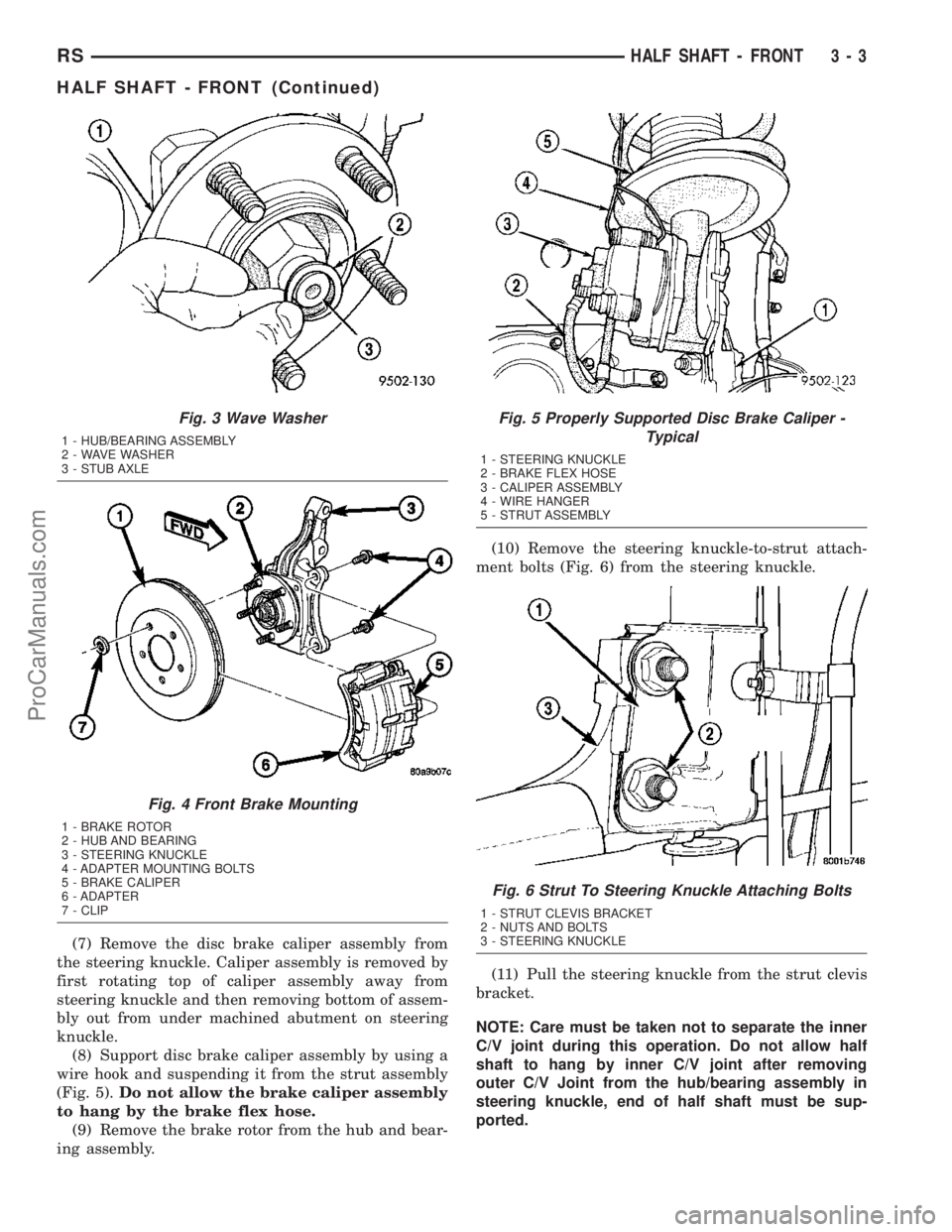
(7) Remove the disc brake caliper assembly from
the steering knuckle. Caliper assembly is removed by
first rotating top of caliper assembly away from
steering knuckle and then removing bottom of assem-
bly out from under machined abutment on steering
knuckle.
(8) Support disc brake caliper assembly by using a
wire hook and suspending it from the strut assembly
(Fig. 5).Do not allow the brake caliper assembly
to hang by the brake flex hose.
(9) Remove the brake rotor from the hub and bear-
ing assembly.(10) Remove the steering knuckle-to-strut attach-
ment bolts (Fig. 6) from the steering knuckle.
(11) Pull the steering knuckle from the strut clevis
bracket.
NOTE: Care must be taken not to separate the inner
C/V joint during this operation. Do not allow half
shaft to hang by inner C/V joint after removing
outer C/V Joint from the hub/bearing assembly in
steering knuckle, end of half shaft must be sup-
ported.
Fig. 3 Wave Washer
1 - HUB/BEARING ASSEMBLY
2 - WAVE WASHER
3 - STUB AXLE
Fig. 4 Front Brake Mounting
1 - BRAKE ROTOR
2 - HUB AND BEARING
3 - STEERING KNUCKLE
4 - ADAPTER MOUNTING BOLTS
5 - BRAKE CALIPER
6 - ADAPTER
7 - CLIP
Fig. 5 Properly Supported Disc Brake Caliper -
Typical
1 - STEERING KNUCKLE
2 - BRAKE FLEX HOSE
3 - CALIPER ASSEMBLY
4 - WIRE HANGER
5 - STRUT ASSEMBLY
Fig. 6 Strut To Steering Knuckle Attaching Bolts
1 - STRUT CLEVIS BRACKET
2 - NUTS AND BOLTS
3 - STEERING KNUCKLE
RSHALF SHAFT - FRONT3-3
HALF SHAFT - FRONT (Continued)
ProCarManuals.com
Page 103 of 2177
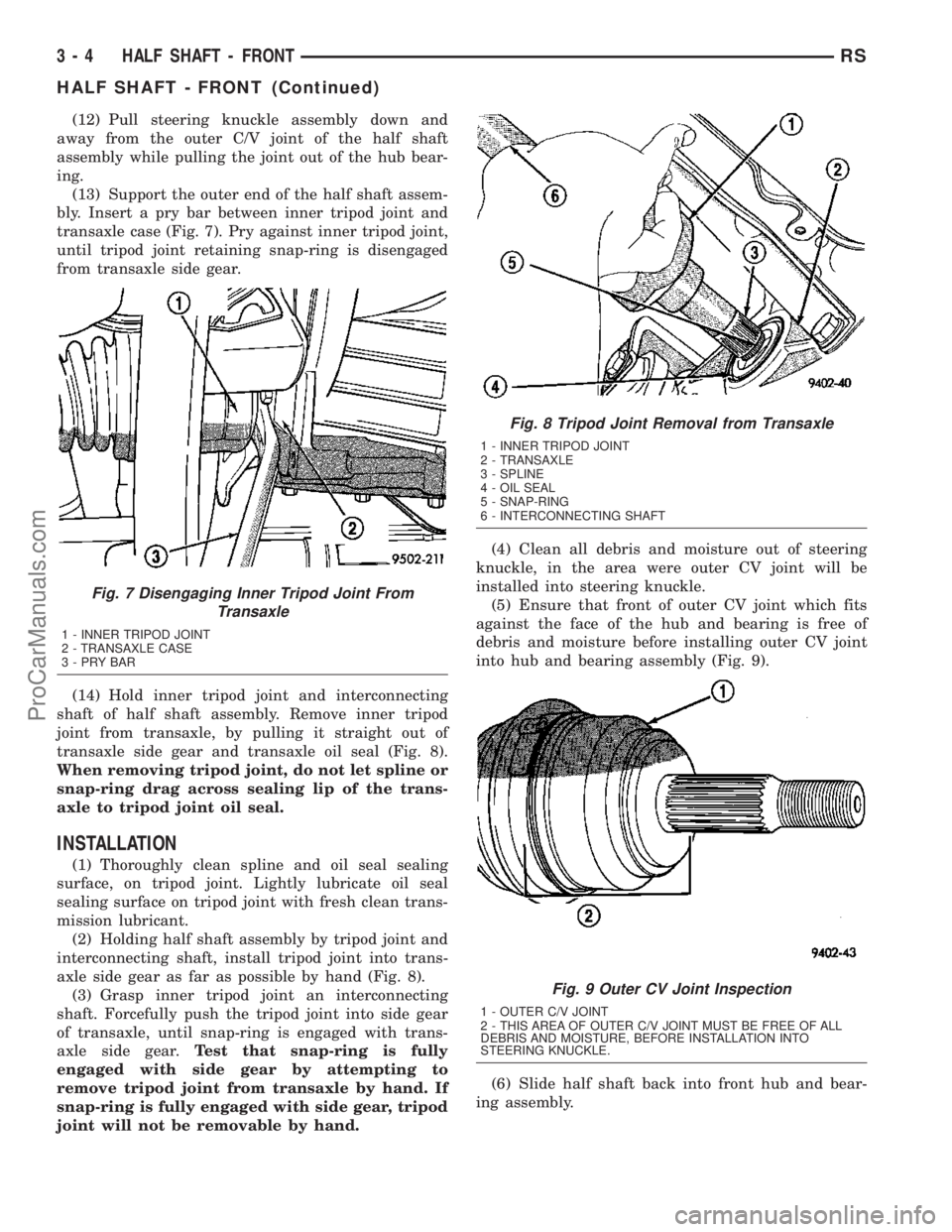
(12) Pull steering knuckle assembly down and
away from the outer C/V joint of the half shaft
assembly while pulling the joint out of the hub bear-
ing.
(13) Support the outer end of the half shaft assem-
bly. Insert a pry bar between inner tripod joint and
transaxle case (Fig. 7). Pry against inner tripod joint,
until tripod joint retaining snap-ring is disengaged
from transaxle side gear.
(14) Hold inner tripod joint and interconnecting
shaft of half shaft assembly. Remove inner tripod
joint from transaxle, by pulling it straight out of
transaxle side gear and transaxle oil seal (Fig. 8).
When removing tripod joint, do not let spline or
snap-ring drag across sealing lip of the trans-
axle to tripod joint oil seal.
INSTALLATION
(1) Thoroughly clean spline and oil seal sealing
surface, on tripod joint. Lightly lubricate oil seal
sealing surface on tripod joint with fresh clean trans-
mission lubricant.
(2) Holding half shaft assembly by tripod joint and
interconnecting shaft, install tripod joint into trans-
axle side gear as far as possible by hand (Fig. 8).
(3) Grasp inner tripod joint an interconnecting
shaft. Forcefully push the tripod joint into side gear
of transaxle, until snap-ring is engaged with trans-
axle side gear.Test that snap-ring is fully
engaged with side gear by attempting to
remove tripod joint from transaxle by hand. If
snap-ring is fully engaged with side gear, tripod
joint will not be removable by hand.(4) Clean all debris and moisture out of steering
knuckle, in the area were outer CV joint will be
installed into steering knuckle.
(5) Ensure that front of outer CV joint which fits
against the face of the hub and bearing is free of
debris and moisture before installing outer CV joint
into hub and bearing assembly (Fig. 9).
(6) Slide half shaft back into front hub and bear-
ing assembly.
Fig. 7 Disengaging Inner Tripod Joint From
Transaxle
1 - INNER TRIPOD JOINT
2 - TRANSAXLE CASE
3-PRYBAR
Fig. 8 Tripod Joint Removal from Transaxle
1 - INNER TRIPOD JOINT
2 - TRANSAXLE
3 - SPLINE
4 - OIL SEAL
5 - SNAP-RING
6 - INTERCONNECTING SHAFT
Fig. 9 Outer CV Joint Inspection
1 - OUTER C/V JOINT
2 - THIS AREA OF OUTER C/V JOINT MUST BE FREE OF ALL
DEBRIS AND MOISTURE, BEFORE INSTALLATION INTO
STEERING KNUCKLE.
3 - 4 HALF SHAFT - FRONTRS
HALF SHAFT - FRONT (Continued)
ProCarManuals.com
Page 105 of 2177
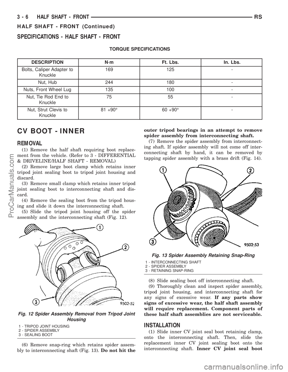
SPECIFICATIONS - HALF SHAFT - FRONT
TORQUE SPECIFICATIONS
DESCRIPTION N´m Ft. Lbs. In. Lbs.
Bolts, Caliper Adapter to
Knuckle169 125 -
Nut, Hub 244 180 -
Nuts, Front Wheel Lug 135 100 -
Nut, Tie Rod End to
Knuckle75 55 -
Nut, Strut Clevis to
Knuckle81 +90É 60 +90É -
CV BOOT - INNER
REMOVAL
(1) Remove the half shaft requiring boot replace-
ment from the vehicle. (Refer to 3 - DIFFERENTIAL
& DRIVELINE/HALF SHAFT - REMOVAL)
(2) Remove large boot clamp which retains inner
tripod joint sealing boot to tripod joint housing and
discard.
(3) Remove small clamp which retains inner tripod
joint sealing boot to interconnecting shaft and dis-
card.
(4) Remove the sealing boot from the tripod hous-
ing and slide it down the interconnecting shaft.
(5) Slide the tripod joint housing off the spider
assembly and the interconnecting shaft (Fig. 12).
(6) Remove snap-ring which retains spider assem-
bly to interconnecting shaft (Fig. 13).Do not hit theouter tripod bearings in an attempt to remove
spider assembly from interconnecting shaft.
(7) Remove the spider assembly from interconnect-
ing shaft. If spider assembly will not come off inter-
connecting shaft by hand, it can be removed by
tapping spider assembly with a brass drift (Fig. 14).
(8) Slide sealing boot off interconnecting shaft.
(9) Thoroughly clean and inspect spider assembly,
tripod joint housing, and interconnecting shaft for
any signs of excessive wear.If any parts show
signs of excessive wear, the half shaft assembly
will require replacement. Component parts of
these half shaft assemblies are not serviceable.
INSTALLATION
(1) Slide inner CV joint seal boot retaining clamp,
onto the interconnecting shaft. Then, slide the
replacement inner CV joint sealing boot onto the
interconnecting shaft.Inner CV joint seal boot
Fig. 12 Spider Assembly Removal from Tripod Joint
Housing
1 - TRIPOD JOINT HOUSING
2 - SPIDER ASSEMBLY
3 - SEALING BOOT
Fig. 13 Spider Assembly Retaining Snap-Ring
1 - INTERCONNECTING SHAFT
2 - SPIDER ASSEMBLY
3 - RETAINING SNAP-RING
3 - 6 HALF SHAFT - FRONTRS
HALF SHAFT - FRONT (Continued)
ProCarManuals.com
Page 108 of 2177

CAUTION: When venting the inner CV joint assem-
bly, use care so that the inner CV sealing boot does
not get punctured, or in any other way damaged. If
sealing boot is punctured, or damaged in any way
while being vented, the sealing boot can not be
used.
(11) Insert a trim stick between the CV joint hous-
ing and the sealing boot insert to vent inner CV joint
assembly (Fig. 22).When inserting trim stick
between tripod housing and sealing boot
ensure trim stick is held flat and firmly against
the tripod housing. If this is not done damage
to the sealing boot can occur.
(12) With trim stick inserted between sealing boot
insert and the CV joint housing, position the inter-
connecting shaft so it is at the center of its travel in
the tripod joint housing. Remove the trim stick from
between the sealing boot insert and the CV joint
housing.This procedure will equalize the air
pressure in the CV joint, preventing premature
sealing boot failure.
(13) Clamp CV joint sealing boot to CV joint, using
required procedure for type of boot clamp application.CRIMP TYPE BOOT CLAMP
If seal boot uses crimp type boot clamp, use the fol-
lowing procedure to install the retaining clamp.
(1) Place crimping tool C-4975-A over bridge of
clamp (Fig. 23).
(2) Tighten nut on crimping tool C-4975-A until
jaws on tool are closed completely together, face to
face (Fig. 24).
Fig. 22 Trim Stick Inserted for Venting CV Joint
1 - INNER CV JOINT SEALING BOOT
2 - SEALING BOOT CLAMP
3 - INNER CV JOINT HOUSING
4 - TRIM STICK
Fig. 23 Crimping Tool Installed on Sealing Boot
Clamp
1 - CLAMP
2 - TRIPOD JOINT HOUSING
3 - SPECIAL TOOL C-4975-A
4 - SEALING BOOT
Fig. 24 Sealing Boot Retaining Clamp Installed
1 - CLAMP
2 - TRIPOD HOUSING
3 - SPECIAL TOOL C-4975-A
4 - JAWS OF SPECIAL TOOL C-4975-A MUST BE CLOSED
COMPLETELY TOGETHER HERE
5 - SEALING BOOT
RSHALF SHAFT - FRONT3-9
CV BOOT - INNER (Continued)
ProCarManuals.com
Page 109 of 2177

LATCHING TYPE BOOT CLAMP
If seal boot uses low profile latching type boot
clamp, use the following procedure to install the
retaining clamp.
(1) Place prongs of clamp locking tool in the holes
of the clamp (Fig. 25).
(2) Squeeze tool together until top band of clamp is
latched behind the two tabs on lower band of clamp
(Fig. 26).
(14) Install the half shaft back into the vehicle.
(Refer to 3 - DIFFERENTIAL & DRIVELINE/HALF
SHAFT - INSTALLATION)
CV BOOT - OUTER
REMOVAL
(1) Remove half shaft assembly requiring boot
replacement from vehicle. (Refer to 3 - DIFFEREN-
TIAL & DRIVELINE/HALF SHAFT - REMOVAL)
(2) Remove large boot clamp retaining CV joint
sealing boot to CV joint housing (Fig. 27) and dis-
card.
(3) Remove small clamp that retains outer CV
joint sealing boot to interconnecting shaft and dis-
card.
(4) Remove sealing boot from outer CV joint hous-
ing and slide it down interconnecting shaft.
(5) Wipe away grease to expose outer CV joint to
interconnecting shaft retaining ring.
(6) Spread ears apart on CV joint assembly to
interconnecting shaft retaining ring (Fig. 28).
(7) Slide outer CV joint assembly off end of inter-
connecting shaft.
(8) Slide sealing boot off interconnecting shaft.
(9) Thoroughly clean and inspect outer CV joint
assembly and interconnecting joint for any signs of
excessive wear.If any parts show signs of exces-
sive wear, the half shaft assembly will require
replacement. Component parts of these half
shaft assemblies are not serviceable.
INSTALLATION
(1) Slide the new small diameter seal boot retain-
ing clamp onto the interconnecting shaft. Then slide
the replacement outer CV joint assembly sealing boot
onto the interconnecting shaft.
Fig. 25 Clamping Tool Installed on Sealing Boot
Clamp
1 - CLAMP
2 - TOOL YA3050, OR EQUIVALENT
3 - SEALING BOOT
Fig. 26 Sealing Boot Clamp Correctly Installed
1 - INNER TRIPOD JOINT HOUSING
2 - TOP BAND OF CLAMP MUST BE RETAINED BY TABS AS
SHOWN HERE TO CORRECTLY LATCH BOOT CLAMP
3 - SEALING BOOT
Fig. 27 Outer CV Joint Seal Boot Clamps
1 - SMALL CLAMP
2 - SEALING BOOT
3 - OUTER C/V JOINT HOUSING
4 - LARGE CLAMP
5 - INTERCONNECTING SHAFT
3 - 10 HALF SHAFT - FRONTRS
CV BOOT - INNER (Continued)
ProCarManuals.com
Page 112 of 2177

HALF SHAFT - REAR
TABLE OF CONTENTS
page page
HALF SHAFT - REAR
DESCRIPTION.........................13
DIAGNOSIS AND TESTING - HALF SHAFT....13
REMOVAL.............................13
INSTALLATION.........................14SPECIFICATIONS - HALF SHAFT - FRONT . . . 15
CV BOOT - INNER/OUTER
REMOVAL.............................15
INSTALLATION.........................17
HALF SHAFT - REAR
DESCRIPTION
The inner and outer joints of both half shaft
assemblies are tripod joints. The tripod joints are
true constant velocity (CV) joint assemblies, which
allow for the changes in half shaft length through
the jounce and rebound travel of the rear suspension.
On vehicles equipped with ABS brakes, the outer
CV joint is equipped with a tone wheel used to deter-
mine vehicle speed for ABS brake operation.
The inner tripod joint of both half shafts is bolted
rear differential assembly's output flanges. The outer
CV joint has a stub shaft that is splined into the
wheel hub and retained by a steel hub nut.
DIAGNOSIS AND TESTING - HALF SHAFT
VEHICLE INSPECTION
(1) Check for grease in the vicinity of the inboard
tripod joint and outboard CV joint; this is a sign of
inner or outer joint seal boot or seal boot clamp dam-
age.
NOISE AND/OR VIBRATION IN TURNS
A clicking noise and/or a vibration in turns could
be caused by one of the following conditions:
²Damaged outer CV or inner tripod joint seal
boot or seal boot clamps. This will result in the loss
and/or contamination of the joint grease, resulting in
inadequate lubrication of the joint.
²Noise may also be caused by another component
of the vehicle coming in contact with the half shafts.
CLUNKING NOISE DURING ACCELERATION
This noise may be a result of one of the following
conditions:
²A torn seal boot on the inner or outer joint of the
half shaft assembly.
²A loose or missing clamp on the inner or outer
joint of the half shaft assembly.
²A damaged or worn half shaft CV joint.
SHUDDER OR VIBRATION DURING ACCELERATION
This problem could be a result of:
²A worn or damaged half shaft inner tripod joint.
²A sticking tripod joint spider assembly (inner tri-
pod joint only).
²Improper wheel alignment. (Refer to 2 - SUS-
PENSION/WHEEL ALIGNMENT - STANDARD
PROCEDURE)
VIBRATION AT HIGHWAY SPEEDS
This problem could be a result of:
²Foreign material (mud, etc.) packed on the back-
side of the wheel(s).
²Out of balance tires or wheels. (Refer to 22 -
TIRES/WHEELS - STANDARD PROCEDURE)
²Improper tire and/or wheel runout. (Refer to 22 -
TIRES/WHEELS - DIAGNOSIS AND TESTING)
REMOVAL
(1) Lift vehicle on hoist so that the wheels hang
freely.
(2) Remove rear wheel.
(3) Remove cotter pin, nut lock, and spring washer
(Fig. 1).
Fig. 1 Cotter Pin, Nut Lock, And Spring Washer
1 - HUB NUT
2 - NUT LOCK
3 - COTTER PIN
4 - SPRING WASHER
RSHALF SHAFT - REAR3-13
ProCarManuals.com
Page 113 of 2177
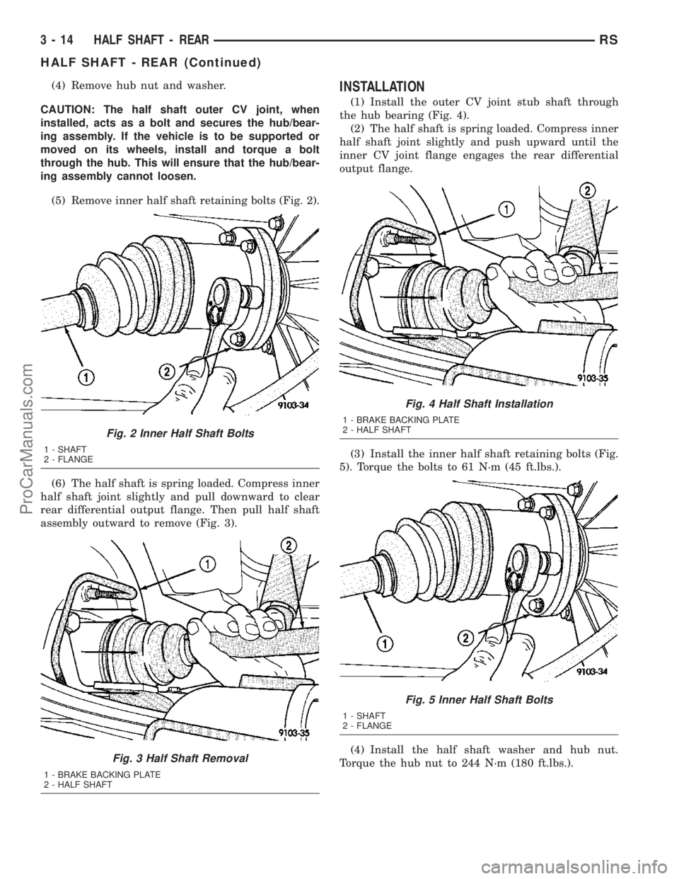
(4) Remove hub nut and washer.
CAUTION: The half shaft outer CV joint, when
installed, acts as a bolt and secures the hub/bear-
ing assembly. If the vehicle is to be supported or
moved on its wheels, install and torque a bolt
through the hub. This will ensure that the hub/bear-
ing assembly cannot loosen.
(5) Remove inner half shaft retaining bolts (Fig. 2).
(6) The half shaft is spring loaded. Compress inner
half shaft joint slightly and pull downward to clear
rear differential output flange. Then pull half shaft
assembly outward to remove (Fig. 3).INSTALLATION
(1) Install the outer CV joint stub shaft through
the hub bearing (Fig. 4).
(2) The half shaft is spring loaded. Compress inner
half shaft joint slightly and push upward until the
inner CV joint flange engages the rear differential
output flange.
(3) Install the inner half shaft retaining bolts (Fig.
5). Torque the bolts to 61 N´m (45 ft.lbs.).
(4) Install the half shaft washer and hub nut.
Torque the hub nut to 244 N´m (180 ft.lbs.).
Fig. 2 Inner Half Shaft Bolts
1 - SHAFT
2 - FLANGE
Fig. 3 Half Shaft Removal
1 - BRAKE BACKING PLATE
2 - HALF SHAFT
Fig. 4 Half Shaft Installation
1 - BRAKE BACKING PLATE
2 - HALF SHAFT
Fig. 5 Inner Half Shaft Bolts
1 - SHAFT
2 - FLANGE
3 - 14 HALF SHAFT - REARRS
HALF SHAFT - REAR (Continued)
ProCarManuals.com
Page 114 of 2177

(5) Install the spring washer, nut lock, and a new
cotter pin (Fig. 6). Be sure to wrap the cotter pin
prongs tightly around the hub nut lock.
(6) Install rear wheel. Torque the lug nuts to 135
N´m (100 ft.lbs.).
SPECIFICATIONS - HALF SHAFT - FRONT
TORQUE SPECIFICATIONS
DESCRIPTION N´m Ft. Lbs. In. Lbs.
Nut, Hub 244 180 -
Nuts, Rear Wheel Lug 135 100 -
Bolt, Half Shaft to Output
Flange61 45 -
CV BOOT - INNER/OUTER
REMOVAL
(1) Remove half shaft from vehicle. (Refer to 3 -
DIFFERENTIAL & DRIVELINE/HALF SHAFT -
REMOVAL)
(2) Clamp the half shaft into a suitable vise with
protective jaws clamped onto the interconnecting
shaft (Fig. 7).
Fig. 6 Cotter Pin, Nut Lock, And Spring Washer
1 - HUB NUT
2 - NUT LOCK
3 - COTTER PIN
4 - SPRING WASHER
Fig. 7 Clamp Shaft In Soft Jawed Vice
1 - HALF SHAFT BOOT
2 - HALF SHAFT
3 - VISE
RSHALF SHAFT - REAR3-15
HALF SHAFT - REAR (Continued)
ProCarManuals.com
Page 115 of 2177

(3) Remove the large and small diameter retaining
clamps holding the CV boot to the CV joint and the
interconnecting shaft (Fig. 8).
(4) Pull the boot back from the CV joint (Fig. 9).(5) Remove the CV housing from the interconnect-
ing shaft and tripod assembly (Fig. 10).
(6) Remove the snap-ring holding the tripod
assembly onto the interconnecting shaft (Fig. 11).
Fig. 8 Remove Boot Clamps
1 - HALF SHAFT BOOT
2 - CLAMP
Fig. 9 Pull Back Boot
1 - HALF SHAFT BOOT
2 - HALF SHAFT JOINT
Fig. 10 Remove CV Housing
1 - HALF SHAFT JOINT HOUSING
2 - BOOT
Fig. 11 Remove Snap-Ring
1 - SNAP RING
2 - HALF SHAFT BOOT
3 - TRIPOD ASSEMBLY
4 - SNAP RING PLIERS
3 - 16 HALF SHAFT - REARRS
CV BOOT - INNER/OUTER (Continued)
ProCarManuals.com