wheel CHRYSLER CARAVAN 2005 Service Manual
[x] Cancel search | Manufacturer: CHRYSLER, Model Year: 2005, Model line: CARAVAN, Model: CHRYSLER CARAVAN 2005Pages: 2339, PDF Size: 59.69 MB
Page 1215 of 2339

(6) Drain engine oil and remove oil filter.
(7) Remove crankshaft vibration damper (Refer to
9 - ENGINE/ENGINE BLOCK/VIBRATION
DAMPER - REMOVAL).
(8) Remove engine mount support bracket.
(9) Remove front timing belt covers (Refer to 9 -
ENGINE/VALVE TIMING/TIMING BELT COVER(S)
- REMOVAL).
(10) Remove the timing belt (Refer to 9 - ENGINE/
VALVE TIMING/TIMING BELT AND SPROCKETS -
REMOVAL).
(11) Remove the rear timing belt cover (Refer to 9
- ENGINE/VALVE TIMING/TIMING BELT COV-
ER(S) - REMOVAL).
(12) Remove the oil pan (Refer to 9 - ENGINE/LU-
BRICATION/OIL PAN - REMOVAL).
(13) Remove oil pump pick-up tube.
(14) Remove the crankshaft sprocket and oil pump
(Refer to 9 - ENGINE/LUBRICATION/OIL PUMP -
REMOVAL).
(15) Remove balance shafts and housing assembly
(Refer to 9 - ENGINE/VALVE TIMING/BALANCE
SHAFT - REMOVAL).
(16) Remove crankshaft position sensor.
NOTE: If piston/connecting rod replacement is nec-
essary, remove cylinder head (Refer to 9 - ENGINE/
CYLINDER HEAD - REMOVAL).
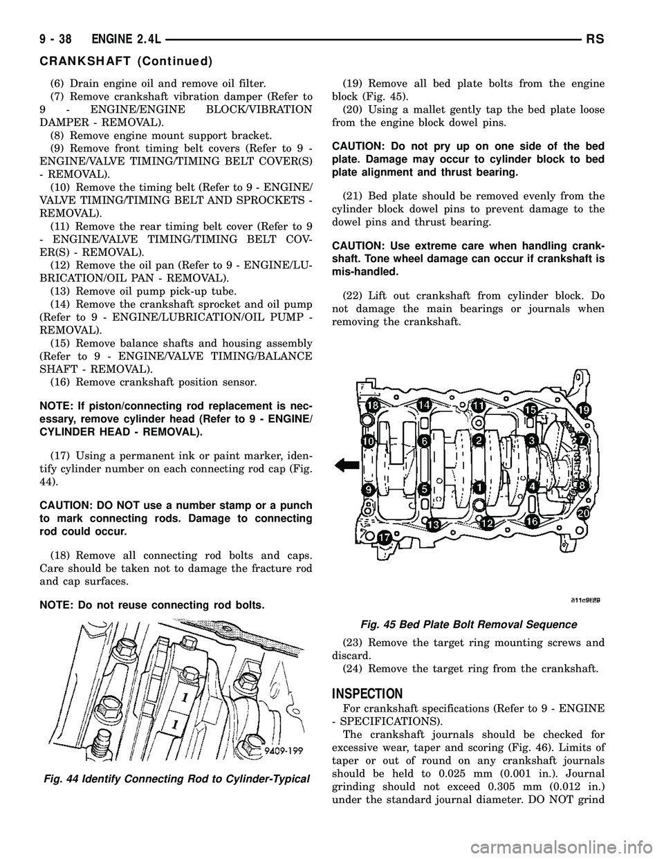
(17) Using a permanent ink or paint marker, iden-
tify cylinder number on each connecting rod cap (Fig.
44).
CAUTION: DO NOT use a number stamp or a punch
to mark connecting rods. Damage to connecting
rod could occur.
(18) Remove all connecting rod bolts and caps.
Care should be taken not to damage the fracture rod
and cap surfaces.
NOTE: Do not reuse connecting rod bolts.(19) Remove all bed plate bolts from the engine
block (Fig. 45).
(20) Using a mallet gently tap the bed plate loose
from the engine block dowel pins.
CAUTION: Do not pry up on one side of the bed
plate. Damage may occur to cylinder block to bed
plate alignment and thrust bearing.
(21) Bed plate should be removed evenly from the
cylinder block dowel pins to prevent damage to the
dowel pins and thrust bearing.
CAUTION: Use extreme care when handling crank-
shaft. Tone wheel damage can occur if crankshaft is
mis-handled.
(22) Lift out crankshaft from cylinder block. Do
not damage the main bearings or journals when
removing the crankshaft.
(23) Remove the target ring mounting screws and
discard.
(24) Remove the target ring from the crankshaft.
INSPECTION
For crankshaft specifications (Refer to 9 - ENGINE
- SPECIFICATIONS).
The crankshaft journals should be checked for
excessive wear, taper and scoring (Fig. 46). Limits of
taper or out of round on any crankshaft journals
should be held to 0.025 mm (0.001 in.). Journal
grinding should not exceed 0.305 mm (0.012 in.)
under the standard journal diameter. DO NOT grind
Fig. 44 Identify Connecting Rod to Cylinder-Typical
Fig. 45 Bed Plate Bolt Removal Sequence
9 - 38 ENGINE 2.4LRS
CRANKSHAFT (Continued)
Page 1216 of 2339

thrust faces of No. 3 main bearing. DO NOT nick
crank pin or bearing fillets. After grinding, remove
rough edges from crankshaft oil holes and clean out
all passages.
CAUTION: With the nodular cast iron crankshafts, it
is important that the final paper or cloth polish be
in the same direction as normal rotation in the
engine.
INSTALLATION - CRANKSHAFT
CRANKSHAFT MAIN BEARING LOCATION
The crankshaft is supported in five main bearings.
All upper bearing shells in the crankcase have oil
grooves and holes. All lower bearing shellsexcept
for the thrust bearing half have oil grooves and holes
(Fig. 47). Crankshaft end play is controlled by a
flanged bearing on the number three main bearing
journal.(1) Install the main bearing upper shells with the
lubrication groove and oil hole in the engine block
(Fig. 48).
(2) Make certain oil holes in block line up with oil
hole in bearings and bearing tabs seat in the block
tab slots.
NOTE: If the crankshaft is sent out for machine
work, it must be balenced as an assembly with the
target ring installed.
(3) Clean crankshaft and target ring with
MOPARtbrake parts cleaner and dry with com-
pressed air to ensure that the crankshaft mating sur-
face and target ring mounting holes are free from oil
and lock patch debris.
NOTE: Always use NEW mounting screws whether
installing original or new target ring.
(4) InstallNEWmounting screws finger tight
starting with the #1 location. (Fig. 49) Make sure
engagment occurs with the shoulder of the screw and
mounting hole before starting all other screws.
(5) Torque all mounting screws with T30 torx bit
to 13 Nm (110 in-lbs) following the torque sequence.
CAUTION: Use extreme care when handling crank-
shaft. Tone wheel damage can occur if crankshaft is
mis-handled.
CAUTION: Do not get oil on the bed plate mating
surface. It will affect the ability of the sealer to seal
the bed plate to cylinder block.
Fig. 46 Crankshaft Journal Measurements - Typical
Fig. 47 Main Bearing Identification
1 - OIL GROOVE
2 - MAIN BEARINGS
3 - OIL HOLE
4 - LOWER THRUST BEARING PLAIN (NO OIL HOLE OR
GROOVE)
Fig. 48 Installing Main Bearing Upper Shell
1 - LUBRICATION GROOVES
2 - OIL HOLES
RSENGINE 2.4L9-39
CRANKSHAFT (Continued)
Page 1227 of 2339

ENGINE MOUNTING
DESCRIPTION
The engine mounting system consist of four
mounts; right and a left side support the powertrain,
and a front and a rear mount control powertrain
torque. The right side mount is a hydro-type (Fig.
78), all others are of molded rubber material.
FRONT MOUNT
REMOVAL
(1) Raise vehicle on hoist.
(2) Remove the front engine mount through bolt
from the insulator (Fig. 79).
(3) Remove the engine front mount bolts and
remove the insulator assembly (Fig. 79).
(4) Remove the front mounting bracket from
engine, if necessary (Fig. 79).
INSTALLATION
(1) Install the front mount bracket to engine, if
removed (Fig. 79).
(2) Install the insulator mount assembly (Fig. 79).
(3) Install the front engine mount through bolt to
the insulator (Fig. 79).
(4) Lower the vehicle.
LEFT MOUNT
REMOVAL
(1) Raise the vehicle on hoist.
(2) Remove the left front wheel.
(3) Remove the left mount through bolt access
cover.
(4) Support the transaxle with a suitable jack.
(5) Remove the engine front mount through bolt to
allow left mount removal clearance (Fig. 79).
(6) Remove the left mount through frame rail bolt
(Fig. 80).
(7) Lower transaxle for access to horizontal bolts.
(8) Remove the horizontal bolts from the mount to
the transaxle (Fig. 81).
NOTE: To remove mount, additional lowering of
transaxle may be required.
(9) Remove left mount.
INSTALLATION
(1) Install left mount on transaxle (Fig. 81).
(2) Raise transaxle with jack until left mount is in
position.
(3) Install left mount through bolt (Fig. 80).
Fig. 78 Engine Hydro-type Mount - Right Side
1 - BOLT
2 - BOLT
3 - FRAME RAIL
4 - RIGHT MOUNT - 2.4L ENGINE
5 - RIGHT MOUNT - 3.3/3.8L ENGINE
Fig. 79 Front Mount and Bracket
1 - BRACKET - FRONT MOUNT
2 - NUT - 68 N´m (50 ft. lbs.)
3 - BOLT - 54 N´m (40 ft. lbs.)
4 - MOUNT - FRONT INSULATOR
5 - BOLT - 68 N´m (50 ft. lbs.)
6 - BOLT - 68 N´m (50 ft. lbs.)
7 - FRONT CROSSMEMBER
9 - 50 ENGINE 2.4LRS
Page 1228 of 2339

(4) Install left mount through bolt access cover.
(5) Install front mount through bolt (Fig. 79).
(6) Install left front wheel.
(7) Lower vehicle.
REAR MOUNT
REMOVAL
(1) Raise vehicle on hoist.
(2) Remove the rear mount heat shield (Fig. 82).
(3) Remove the through bolt from the mount and
rear mount bracket (Fig. 83).
(4) Remove the mount bolts (Fig. 83).
(5) Remove the rear mount (Fig. 83).
(6) For rear mount bracket removal, remove the
bolts attaching bracket to transaxle (Fig. 84).
(7) Remove rear mount bracket.
Fig. 80 Left Mount To Bracket
1 - BOLT - BRACKET TO FRAME RAIL 68 N´m (50 ft. lbs.)
2 - BOLT - MOUNT TO RAIL THRU 75 N´m (55 ft. lbs.)
3 - BOLT - LEFT MOUNT TO TRANSAXLE 54 N´m (40 ft. lbs.)
4 - TRANSAXLE
5 - MOUNT - LEFT
6 - BRACKET - LEFT MOUNT
Fig. 81 Left Mount - 41TE Transaxle
1 - LEFT MOUNT ASSEMBLY
2 - BOLT - 54 N´m (40 ft. lbs.)
3 - TRANSAXLE - 41TE
Fig. 82 Rear Mount Heat Shield
1 - BOLT - HEAT SHIELD 11 N´m (100 in. lbs.)
2 - HEAT SHIELD
3 - CLIP
4 - REAR MOUNT
Fig. 83 Rear Mount
1 - BOLT 54 N´m (40 ft. lbs.)
2 - REAR MOUNT BRACKET
3 - THRU-BOLT 54 N´m (40 ft. lbs.)
4 - REAR MOUNT
RSENGINE 2.4L9-51
LEFT MOUNT (Continued)
Page 1242 of 2339

REAR COVER
(1) Install rear timing belt cover and fasteners.
Torque fasteners to specified values (Fig. 118).
CAUTION: Do not use an impact wrench for tighten-
ing camshaft sprocket bolt. Damage to the timing
locating pin can occur. Hand tighten using a
wrench ONLY.
(2) Install camshaft sprockets. Hold sprockets with
Special Tool 6848 and tighten center bolt to 101 N´m
(75 ft. lbs.) (Fig. 116).
(3) Install timing belt idler pulley and tighten
mounting bolt to 61 N´m (45 ft. lbs.) (Fig. 117).
(4) Install timing belt (Refer to 9 - ENGINE/
VALVE TIMING/TIMING BELT AND SPROCKETS -
INSTALLATION).
(5) Install engine mount bracket and tighten bolts
to 61 N´m (45 ft. lbs.) (Fig. 115).
(6) Install front covers.
TIMING BELT AND
SPROCKET(S)
REMOVAL
REMOVAL - TIMING BELT
(1) Remove air cleaner upper cover, housing, and
clean air tube.
(2) Remove make-up air hose from cylinder head
cover.
(3) Raise vehicle on hoist.
(4) Remove right front wheel.
(5) Remove right inner splash shield.
(6) Remove accessory drive belts (Refer to 7 -
COOLING/ACCESSORY DRIVE/DRIVE BELTS -
REMOVAL).
(7) Remove crankshaft vibration damper (Refer to
9 - ENGINE/ENGINE BLOCK/VIBRATION
DAMPER - REMOVAL).
(8) Remove air conditioner/generator belt tensioner
and pulley assembly (Refer to 7 - COOLING/ACCES-
SORY DRIVE/BELT TENSIONERS - REMOVAL).
(9) Remove timing belt lower front cover bolts and
remove cover (Refer to 9 - ENGINE/VALVE TIMING/
TIMING BELT COVER(S) - REMOVAL).
(10) Lower vehicle.
(11) Remove bolts attaching timing belt upper
front cover and remove cover (Refer to 9 - ENGINE/
VALVE TIMING/TIMING BELT COVER(S) -
REMOVAL).
(12) Remove right engine mount (Refer to 9 -
ENGINE/ENGINE MOUNTING/RIGHT MOUNT -
REMOVAL).
(13) Remove engine mount bracket (Fig. 119).
CAUTION: When aligning crankshaft and camshaft
timing marks always rotate engine from crankshaft.
Camshaft should not be rotated after timing belt is
removed. Damage to valve components may occur.
Always align timing marks before removing timing
belt.
(14) Before the removal of the timing belt, rotate
crankshaft until the TDC mark on oil pump housing
aligns with the TDC mark on crankshaft sprocket
(trailing edge of sprocket tooth) (Fig. 120).
NOTE: The crankshaft sprocket TDC mark is
located on the trailing edge of the sprocket tooth.
Failure to align trailing edge of sprocket tooth to
TDC mark on oil pump housing will cause the cam-
shaft timing marks to be misaligned.
(15) Loosen timing belt tensioner lock bolt (Fig.
121).
Fig. 118 Rear Timing Belt Cover Fasteners
1 - M6 BOLTS - 12 N´m (105 in. lbs.)
2 - M8 BOLTS - 28 N´m (250 in. lbs.)
3 - TIMING BELT TENSIONER
RSENGINE 2.4L9-65
TIMING BELT COVER(S) (Continued)
Page 1246 of 2339

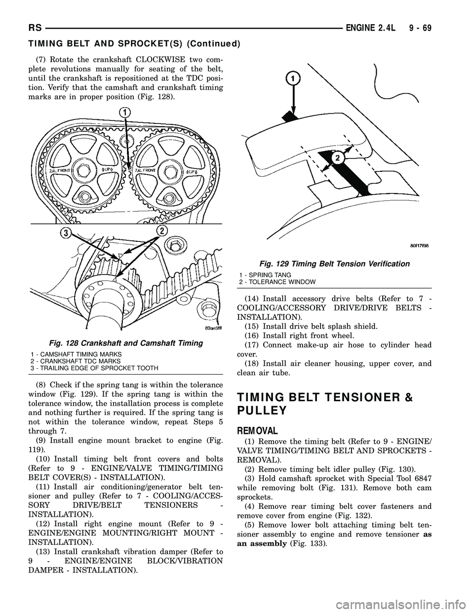
(7) Rotate the crankshaft CLOCKWISE two com-
plete revolutions manually for seating of the belt,
until the crankshaft is repositioned at the TDC posi-
tion. Verify that the camshaft and crankshaft timing
marks are in proper position (Fig. 128).
(8) Check if the spring tang is within the tolerance
window (Fig. 129). If the spring tang is within the
tolerance window, the installation process is complete
and nothing further is required. If the spring tang is
not within the tolerance window, repeat Steps 5
through 7.
(9) Install engine mount bracket to engine (Fig.
119).
(10) Install timing belt front covers and bolts
(Refer to 9 - ENGINE/VALVE TIMING/TIMING
BELT COVER(S) - INSTALLATION).
(11) Install air conditioning/generator belt ten-
sioner and pulley (Refer to 7 - COOLING/ACCES-
SORY DRIVE/BELT TENSIONERS -
INSTALLATION).
(12) Install right engine mount (Refer to 9 -
ENGINE/ENGINE MOUNTING/RIGHT MOUNT -
INSTALLATION).
(13) Install crankshaft vibration damper (Refer to
9 - ENGINE/ENGINE BLOCK/VIBRATION
DAMPER - INSTALLATION).(14) Install accessory drive belts (Refer to 7 -
COOLING/ACCESSORY DRIVE/DRIVE BELTS -
INSTALLATION).
(15) Install drive belt splash shield.
(16) Install right front wheel.
(17) Connect make-up air hose to cylinder head
cover.
(18) Install air cleaner housing, upper cover, and
clean air tube.
TIMING BELT TENSIONER &
PULLEY
REMOVAL
(1) Remove the timing belt (Refer to 9 - ENGINE/
VALVE TIMING/TIMING BELT AND SPROCKETS -
REMOVAL).
(2) Remove timing belt idler pulley (Fig. 130).
(3) Hold camshaft sprocket with Special Tool 6847
while removing bolt (Fig. 131). Remove both cam
sprockets.
(4) Remove rear timing belt cover fasteners and
remove cover from engine (Fig. 132).
(5) Remove lower bolt attaching timing belt ten-
sioner assembly to engine and remove tensioneras
an assembly(Fig. 133).
Fig. 128 Crankshaft and Camshaft Timing
1 - CAMSHAFT TIMING MARKS
2 - CRANKSHAFT TDC MARKS
3 - TRAILING EDGE OF SPROCKET TOOTH
Fig. 129 Timing Belt Tension Verification
1 - SPRING TANG
2 - TOLERANCE WINDOW
RSENGINE 2.4L9-69
TIMING BELT AND SPROCKET(S) (Continued)
Page 1255 of 2339

INSPECTION.........................145
ASSEMBLY...........................146
INSTALLATION........................146
INTAKE MANIFOLD
DESCRIPTION........................147
DIAGNOSIS AND TESTING - INTAKE
MANIFOLD LEAKS....................147
INTAKE MANIFOLD - UPPER
STANDARD PROCEDURE
STANDARD PROCEDURE - MANIFOLD
STRIPPED THREAD REPAIR............147
STANDARD PROCEDURE - INTAKE
MANIFOLD VACUUM PORT REPAIR......148
REMOVAL - UPPER INTAKE MANIFOLD.....148
CLEANING...........................148
INSPECTION.........................149
INSTALLATION - UPPER INTAKE MANIFOLD . 149
INTAKE MANIFOLD - LOWER
REMOVAL - LOWER INTAKE MANIFOLD....150
CLEANING...........................151
INSPECTION.........................151
INSTALLATION - LOWER INTAKE MANIFOLD . 151
EXHAUST MANIFOLD - RIGHT
REMOVAL............................152
CLEANING...........................153
INSPECTION.........................153INSTALLATION........................153
EXHAUST MANIFOLD - LEFT
REMOVAL............................154
CLEANING...........................154
INSPECTION.........................155
INSTALLATION........................155
VALVE TIMING
STANDARD PROCEDURE
STANDARD PROCEDURE - VALVE TIMING
VERIFICATION.......................155
STANDARD PROCEDURE - MEASURING
TIMING CHAIN WEAR.................155
TIMING CHAIN COVER
REMOVAL............................156
INSTALLATION........................157
TIMING CHAIN AND SPROCKETS
REMOVAL
REMOVAL - TIMING CHAIN AND
CAMSHAFT SPROCKET...............159
REMOVAL - CRANKSHAFT SPROCKET . . . 159
INSTALLATION
INSTALLATION - CRANKSHAFT
SPROCKET.........................160
INSTALLATION - TIMING CHAIN AND
CAMSHAFT SPROCKET...............160
ENGINE 3.3/3.8L
DESCRIPTION
The 3.3 Liter (201 cu. in.) and 3.8 Liter (231 cu.
in.) engines are 60É V-6 engines with cast iron cylin-
der blocks and aluminum cylinder heads (Fig. 1). The
engine uses a single, block mounted camshaft with
pushrods to actuate the valves. These engines do not
have provisions for a free wheeling valve train.
The firing order is 1±2±3±4±5±6. The cylinders are
numbered from the front of the engine to the rear.
The front cylinder bank is numbered 2, 4, and 6. The
rear cylinder bank is numbered 1, 3, and 5.
The engine identification number is located on the
rear of the cylinder block just below the cylinder
head (Fig. 2).
DIAGNOSIS AND TESTING
DIAGNOSIS AND TESTING - ENGINE
DIAGNOSIS - INTRODUCTION
Engine diagnosis is helpful in determining the
causes of malfunctions not detected and remedied by
routine maintenance.These malfunctions may be classified as either
mechanical (e.g., a strange noise), or performance
(e.g., engine idles rough and stalls).
Refer to the Engine Mechanical and the Engine
Performance diagnostic charts, for possible causes
and corrections of malfunctions (Refer to 9 - ENGINE
- DIAGNOSIS AND TESTING - MECHANICAL)
(Refer to 9 - ENGINE - DIAGNOSIS AND TESTING
- PERFORMANCE).
For fuel system diagnosis, (Refer to 14 - FUEL
SYSTEM/FUEL DELIVERY - DIAGNOSIS AND
TESTING).
Additional tests and diagnostic procedures may be
necessary for specific engine malfunctions that can-
not be isolated with the Service Diagnosis charts.
Information concerning additional tests and diagno-
sis is provided within the following:
²Cylinder Compression Pressure Test
²Cylinder Combustion Pressure Leakage Test
²Engine Cylinder Head Gasket Failure Diagnosis
²Intake Manifold Leakage Diagnosis
²Hydraulic Lash Adjuster Noise Diagnosis
²Engine Oil Leak Inspection
9 - 78 ENGINE 3.3/3.8LRS
Page 1260 of 2339

CONDITION POSSIBLE CAUSES CORRECTION
MAIN BEARING NOISE 1. Insufficient oil supply. 1. Check engine oil level.
2. Low oil pressure. 2. Check engine oil level. Inspect oil
pump relief valve and spring.
3. Thin or diluted oil. 3. Change oil to correct viscosity.
4. Thick oil 4. (a) Change engine oil and filter.
(b) Run engine to operating
temperature.
(c) Change engine oil and filter
again.
5. Excessive bearing clearance. 5. Measure bearings for correct
clearance. Repair as necessary.
6. Excessive end play. 6. Check thrust bearing for wear on
flanges.
7. Crankshaft journal out-of-round
or worn.7. Replace crankshaft or grind
journals.
8. Loose flywheel or torque
converter.8. Tighten to correct torque.
OIL PRESSURE DROP 1. Low oil level. 1. Check engine oil level.
2. Faulty oil pressure sensor/switch. 2. Replace oil pressure sensor/
switch.
3. Low oil pressure. 3. Check oil pressure sensor/switch
and main bearing oil clearance.
4. Clogged oil filter. 4. Install new oil filter.
5. Worn parts in oil pump. 5. Replace worn parts or pump.
6. Thin or diluted oil. 6. Change oil to correct viscosity.
7. Oil pump relief valve stuck. 7. Remove valve and inspect, clean,
or replace.
8. Oil pump suction tube loose. 8. Remove oil pan and install new
tube or clean, if necessary.
9. Oil pump cover warped or
cracked.9. Install new oil pump.
10. Excessive bearing clearance. 10. Measure bearings for correct
clearance.
OIL LEAKS 1. Misaligned or deteriorated
gaskets.1. Replace gasket(s).
2. Loose fastener, broken or porous
metal part.2. Tighten, repair or replace the
part.
3. Misaligned or deteriorated cup or
threaded plug.3. Replace as necessary.
RSENGINE 3.3/3.8L9-83
ENGINE 3.3/3.8L (Continued)
Page 1307 of 2339

(11) Install the timing chain cover (Refer to 9 -
ENGINE/VALVE TIMING/TIMING CHAIN COVER -
INSTALLATION).
(12) Install the oil pick-up tube and oil pan (Refer
to 9 - ENGINE/LUBRICATION/OIL PAN - INSTAL-
LATION).
(13) Install the transaxle to the engine.
(14) Install the engine assembly (Refer to 9 -
ENGINE - INSTALLATION).
CRANKSHAFT OIL SEAL -
FRONT
REMOVAL
(1) Disconnect negative cable from battery.(2) Raise vehicle on hoist. Remove right wheel and
inner splash shield.
(3) Remove accessory drive belt. (Refer to 7 -
COOLING/ACCESSORY DRIVE/DRIVE BELTS -
REMOVAL)
(4) Remove crankshaft damper. (Refer to 9 -
ENGINE/ENGINE BLOCK/VIBRATION DAMPER -
REMOVAL)
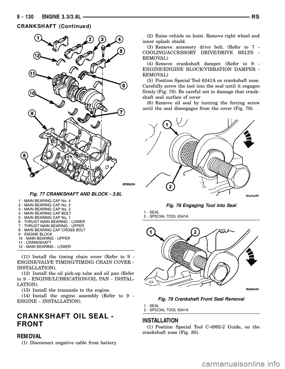
(5) Position Special Tool 6341A on crankshaft nose.
Carefully screw the tool into the seal until it engages
firmly (Fig. 78). Be careful not to damage that crank-
shaft seal surface of cover
(6) Remove oil seal by turning the forcing screw
until the seal disengages from the cover (Fig. 79).
INSTALLATION
(1) Position Special Tool C-4992-2 Guide, on the
crankshaft nose (Fig. 80).
Fig. 77 CRANKSHAFT AND BLOCK - 3.8L
1 - MAIN BEARING CAP No. 4
2 - MAIN BEARING CAP No. 3
3 - MAIN BEARING CAP No. 2
4 - MAIN BEARING CAP BOLT
5 - MAIN BEARING CAP No. 1
6 - THRUST MAIN BEARING - LOWER
7 - THRUST MAIN BEARING - UPPER
8 - MAIN BEARING CAP CROSS BOLT
9 - ENGINE BLOCK
10 - MAIN BEARING - UPPER
11 - CRANKSHAFT
12 - MAIN BEARING - LOWER
Fig. 78 Engaging Tool into Seal
1 - SEAL
2 - SPECIAL TOOL 6341A
Fig. 79 Crankshaft Front Seal Removal
1 - SEAL
2 - SPECIAL TOOL 6341A
9 - 130 ENGINE 3.3/3.8LRS
CRANKSHAFT (Continued)
Page 1308 of 2339

(2) Position new seal over the guide with the seal
spring in the direction of the engine front cover (Fig.
80).
(3) Install seal using Special Tool C-4992-1 until
seal is flush with cover. (Fig. 80).
(4) Install crankshaft damper. (Refer to 9 -
ENGINE/ENGINE BLOCK/VIBRATION DAMPER -
INSTALLATION)
(5) Install accessory drive belt. (Refer to 7 - COOL-
ING/ACCESSORY DRIVE/DRIVE BELTS - INSTAL-
LATION)
(6) Install inner splash shield and right front
wheel.
(7) Lower vehicle and connect negative cable to
battery.
CRANKSHAFT OIL SEAL -
REAR
REMOVAL
(1) Remove the transaxle. Refer to TRANSAXLE
AND POWER TRANSFER UNIT for procedure.
(2) Remove the flex plate. (Refer to 9 - ENGINE/
ENGINE BLOCK/FLEX PLATE - REMOVAL)
(3) Insert a 3/16 flat bladed pry tool between the
dust lip and the metal case of the crankshaft seal.
Angle the pry tool (Fig. 81) through the dust lip
against metal case of the seal. Pry out seal.CAUTION: Do not permit the pry tool blade to con-
tact crankshaft seal surface. Contact of the pry tool
blade against crankshaft edge (chamfer) is permit-
ted.
INSTALLATION
CAUTION: If burr or scratch is present on the
crankshaft edge (chamfer), cleanup with 400 grit
sand paper to prevent seal damage during installa-
tion of new seal.
(1) Place Special Tool 6926-1 magnetic pilot tool on
crankshaft (Fig. 82).
(2) Place seal over Special Tool 6926-1 Pilot. Using
Special Tool 6926-2 Installer with C-4171 Handle,
drive seal into the retainer housing (Fig. 82).
(3) Install the flex plate. (Refer to 9 - ENGINE/
ENGINE BLOCK/FLEX PLATE - INSTALLATION)
(4) Install transaxle. Refer to TRANSAXLE AND
POWER TRANSFER UNIT for procedure.
Fig. 80 CRANKSHAFT FRONT SEAL INSTALLATION
1 - SPECIAL TOOL C-4992-1
2 - SEAL
3 - SPECIAL TOOL C-4992-2
4 - CRANKSHAFT
Fig. 81 Crankshaft Rear Oil Seal - Removal
1 - REAR CRANKSHAFT SEAL
2 - ENGINE BLOCK
3 - ENGINE BLOCK
4 - REAR CRANKSHAFT SEAL METAL CASE
5 - PRY IN THIS DIRECTION
6 - CRANKSHAFT
7 - SCREWDRIVER
8 - REAR CRANKSHAFT SEAL DUST LIP
9 - SCREWDRIVER
RSENGINE 3.3/3.8L9 - 131
CRANKSHAFT OIL SEAL - FRONT (Continued)