fuel filter CHRYSLER CARAVAN 2005 Owner's Manual
[x] Cancel search | Manufacturer: CHRYSLER, Model Year: 2005, Model line: CARAVAN, Model: CHRYSLER CARAVAN 2005Pages: 2339, PDF Size: 59.69 MB
Page 1366 of 2339

FUEL SYSTEM
TABLE OF CONTENTS
page page
FUEL DELIVERY..........................1FUEL INJECTION........................21
FUEL DELIVERY
TABLE OF CONTENTS
page page
FUEL DELIVERY
DESCRIPTION
DESCRIPTION........................2
DESCRIPTION - FFV REPLACEMENT
PARTS...............................2
OPERATION............................2
DIAGNOSIS AND TESTING - FUEL DELIVERY
SYSTEM.............................2
STANDARD PROCEDURE
STANDARD PROCEDURE - FUEL SYSTEM
PRESSURE RELEASE PROCEDURE.......2
STANDARD PROCEDURE - DRAINING
FUEL TANK...........................2
STANDARD PROCEDURE - FUEL
PRESSURE GAUGE....................3
SPECIFICATIONS
FUEL SYSTEM PRESSURE..............4
TORQUE.............................4
SPECIAL TOOLS
FUEL................................4
FUEL LEVEL SENDING UNIT / SENSOR
DESCRIPTION..........................5
OPERATION............................5
REMOVAL.............................5
INSTALLATION..........................6
FUEL LINES
DESCRIPTION - FUEL LINES/HOSES AND
CLAMPS.............................7
STANDARD PROCEDURE - HOSES AND
CLAMP..............................7
FUEL PRESSURE REGULATOR
OPERATION............................7
REMOVAL.............................7
INSTALLATION..........................7
FUEL PUMP
DESCRIPTION..........................8OPERATION............................8
FUEL PUMP MODULE
DESCRIPTION..........................8
OPERATION............................9
REMOVAL
REMOVAL............................9
REMOVAL - FOLD-IN-FLOOR............10
INSTALLATION
INSTALLATION.......................10
INSTALLATION - FOLD-IN-FLOOR.........10
FUEL RAIL
REMOVAL
REMOVAL - 2.4L......................11
REMOVAL - 3.3/3.8L...................11
INSTALLATION
INSTALLATION - 2.4L..................11
INSTALLATION - 3.3/3.8L................12
FUEL TANK
DESCRIPTION.........................12
OPERATION...........................12
REMOVAL
REMOVAL...........................12
REMOVAL - FOLD-IN-FLOOR............13
INSTALLATION
INSTALLATION.......................15
INSTALLATION - FOLD-IN-FLOOR.........16
FUEL TANK FILLER TUBE
REMOVAL.............................16
INSTALLATION.........................17
INLET FILTER
REMOVAL.............................17
INSTALLATION.........................17
QUICK CONNECT FITTING
STANDARD PROCEDURE - QUICK-CONNECT
FITTINGS...........................18
RSFUEL SYSTEM14-1
Page 1367 of 2339
FUEL DELIVERY
DESCRIPTION
DESCRIPTION
The front wheel drive car uses a plastic fuel tank
located rear center of the vehicle.
The Fuel Delivery System consists of: the following
items:
┬▓Electric fuel pump module
┬▓Fuel filter
┬▓Tubes/lines/hoses
┬▓Fuel injectors
The in-tank fuel pump module contains the fuel
pump. The pump is serviced as part of the fuel pump
module. Refer to Fuel Pump Module.
The fuel filter is replaceable only as part of the
fuel pump module.
DESCRIPTION - FFV REPLACEMENT PARTS
Many components in a Flexible Fuel Vehicle (FFV)
are designed to be compatible with ethanol. Always
be sure that the vehicle is serviced with correct etha-
nol compatible parts.
CAUTION: Replacing fuel system components with
non-ethanol compatible components can damage
your vehicle and may void the warranty.
OPERATION
The fuel system provides fuel pressure by an
in-tank pump module. The Powertrain Control Mod-
ule (PCM) controls the operation of the fuel system
by providing battery voltage to the fuel pump
through the fuel pump relay. The PCM requires only
three inputs and a good ground to operate the fuel
pump relay. The three inputs are:
┬▓Ignition voltage
┬▓Crankshaft Position (CKP) sensor
┬▓Camshaft Position (CMP) sensor
DIAGNOSIS AND TESTING - FUEL DELIVERY
SYSTEM
(Refer to Appropriate Diagnostic Information)
STANDARD PROCEDURE
STANDARD PROCEDURE - FUEL SYSTEM
PRESSURE RELEASE PROCEDURE
(1) Remove Fuel Pump relay from Power Distribu-
tion Center (PDC). For location of relay, refer to label
on underside of PDC cover.
(2) Start and run engine until it stalls.(3) Attempt restarting engine until it will no
longer run.
(4) Turn ignition key to OFF position.
(5) Return fuel pump relay to PDC.
(6) One or more Diagnostic Trouble Codes (DTC's)
may have been stored in PCM memory due to fuel
pump relay removal. The DRB IIItscan tool must be
used to erase a DTC.
STANDARD PROCEDURE - DRAINING FUEL
TANK
Two different procedures may be used to drain fuel
tank (lowering tank or using DRBIIItscan tool).
The quickest draining procedure involves lowering
the fuel tank.
WARNING: RELEASE FUEL SYSTEM PRESSURE
BEFORE SERVICING FUEL SYSTEM COMPONENTS.
SERVICE VEHICLES IN WELL VENTILATED AREAS
AND AVOID IGNITION SOURCES. NEVER SMOKE
WHILE SERVICING THE VEHICLE. THIS MAY
RESULT IN PERSONAL INJURY OR DEATH.
As an alternative procedure, the electric fuel pump
may be activated allowing tank to be drained at fuel
rail connection. Refer to DRBIIItscan tool for fuel
pump activation procedures. Before disconnecting
fuel line at fuel rail, release fuel pressure. Refer to
the Fuel System Pressure Release Procedure in this
group for procedures. Disconnect the fuel line at the
fuel rail and remove the plastic retainer from the
fuel rail. Take plastic retainer and install it back into
the fuel line from body. Check the O-ring and make
sure that it is in place and not damaged. Attach end
of special test hose tool number 6539 at fuel line con-
nection from the body line. Position opposite end of
this hose tool to an approved gasoline draining sta-
tion. Activate fuel pump and drain tank until empty.
When done remove the special test hose tool number
6539 from the body line. Remove the plastic retainer
from the special test hose tool number 6539 and rein-
stall it into the fuel line from the body. Check the
O-ring and make sure that it is in place and not
damaged. Install the fuel line to the fuel rail.
If electric fuel pump is not operating, tank must be
lowered for fuel draining. Refer to following proce-
dures.
(1) Remove fuel filler cap.
(2) Perform the Fuel System Pressure Release pro-
cedure.
(3) Disconnect negative cable from battery.
(4) Raise vehicle and support.
(5) Certain models are equipped with a separate
grounding wire (strap) connecting the fuel fill tube
assembly to the body. Disconnect wire by removing
screw.
14 - 2 FUEL DELIVERYRS
Page 1369 of 2339

SPECIFICATIONS
FUEL SYSTEM PRESSURE
400 kpa  34 kpa (58 psi   5 psi)
TORQUE
DESCRIPTION N┬┤m Ft. Lbs. In. Lbs.
Fuel Filler Neck Clamp 3.3 30
Fuel Rail 2.4L 22 195
Fuel Rail 3.3/3.8L 11.8 105
Fuel Tank Strap 54 40
Fuel Tank T Strap 28.2 250
Fuel Filter Bolt 4.5 40
SPECIAL TOOLS
FUEL
Pressure Gauge Assembly C┬▒4799┬▒B
Fuel Pressure Test Adapter 6539
Spanner Wrench 6856
LOCKRING REMOVER/INSTALLER #9340
Fuel Line Adapter 1/4
14 - 4 FUEL DELIVERYRS
FUEL DELIVERY (Continued)
Page 1374 of 2339
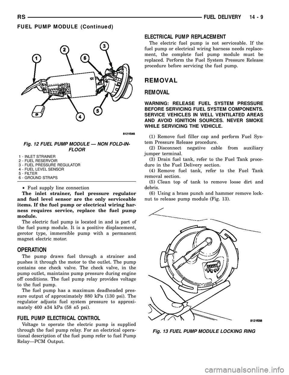
┬▓Fuel supply line connection
The inlet strainer, fuel pressure regulator
and fuel level sensor are the only serviceable
items. If the fuel pump or electrical wiring har-
ness requires service, replace the fuel pump
module.
The electric fuel pump is located in and is part of
the fuel pump module. It is a positive displacement,
gerotor type, immersible pump with a permanent
magnet electric motor.
OPERATION
The pump draws fuel through a strainer and
pushes it through the motor to the outlet. The pump
contains one check valve. The check valve, in the
pump outlet, maintains pump pressure during engine
off conditions. The fuel pump relay provides voltage
to the fuel pump.
The fuel pump has a maximum deadheaded pres-
sure output of approximately 880 kPa (130 psi). The
regulator adjusts fuel system pressure to approxi-
mately 400  34 kPa (58  5 psi).
FUEL PUMP ELECTRICAL CONTROL
Voltage to operate the electric pump is supplied
through the fuel pump relay. For an electrical opera-
tional description of the fuel pump refer to fuel Pump
RelayÐPCM Output.
ELECTRICAL PUMP REPLACEMENT
The electric fuel pump is not serviceable. If the
fuel pump or electrical wiring harness needs replace-
ment, the complete fuel pump module must be
replaced. Perform the Fuel System Pressure Release
procedure before servicing the fuel pump.
REMOVAL
REMOVAL
WARNING: RELEASE FUEL SYSTEM PRESSURE
BEFORE SERVICING FUEL SYSTEM COMPONENTS.
SERVICE VEHICLES IN WELL VENTILATED AREAS
AND AVOID IGNITION SOURCES. NEVER SMOKE
WHILE SERVICING THE VEHICLE.
(1) Remove fuel filler cap and perform Fuel Sys-
tem Pressure Release procedure.
(2) Disconnect negative cable from auxiliary
jumper terminal.
(3) Drain fuel tank, refer to the Fuel Tank proce-
dure in the Fuel Delivery section.
(4) Remove fuel tank, refer to the Fuel Tank
removal section.
(5) Clean top of tank to remove loose dirt and
debris.
(6) Using a brass punch and hammer remove lock-
nut to release pump module (Fig. 13).
Fig. 12 FUEL PUMP MODULE Ð NON FOLD-IN-
FLOOR
1 - INLET STRAINER
2 - FUEL RESERVOIR
3 - FUEL PRESSURE REGULATOR
4 - FUEL LEVEL SENSOR
5 - FILTER
6 - GROUND STRAPS
Fig. 13 FUEL PUMP MODULE LOCKING RING
RSFUEL DELIVERY14-9
FUEL PUMP MODULE (Continued)
Page 1382 of 2339
(8)For RGDisconnect the vent at the top of the
filler tube.
(9) Remove the ground strap.
(10) Remove filler tube at tank.
INSTALLATION
(1) Install filler tube to tank (Fig. 32).
(2) Install filler tube shield (Fig. 34).
(3) Install the ground strap.
(4)For RGConnect the vent at the top of the filler
tube.
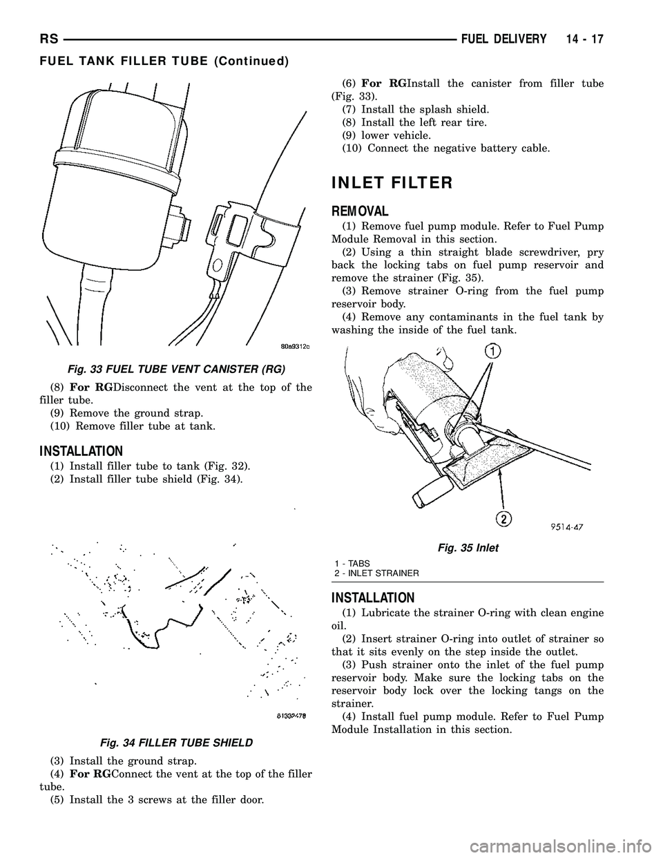
(5) Install the 3 screws at the filler door.(6)For RGInstall the canister from filler tube
(Fig. 33).
(7) Install the splash shield.
(8) Install the left rear tire.
(9) lower vehicle.
(10) Connect the negative battery cable.
INLET FILTER
REMOVAL
(1) Remove fuel pump module. Refer to Fuel Pump
Module Removal in this section.
(2) Using a thin straight blade screwdriver, pry
back the locking tabs on fuel pump reservoir and
remove the strainer (Fig. 35).
(3) Remove strainer O-ring from the fuel pump
reservoir body.
(4) Remove any contaminants in the fuel tank by
washing the inside of the fuel tank.
INSTALLATION
(1) Lubricate the strainer O-ring with clean engine
oil.
(2) Insert strainer O-ring into outlet of strainer so
that it sits evenly on the step inside the outlet.
(3) Push strainer onto the inlet of the fuel pump
reservoir body. Make sure the locking tabs on the
reservoir body lock over the locking tangs on the
strainer.
(4) Install fuel pump module. Refer to Fuel Pump
Module Installation in this section.
Fig. 33 FUEL TUBE VENT CANISTER (RG)
Fig. 34 FILLER TUBE SHIELD
Fig. 35 Inlet
1 - TABS
2 - INLET STRAINER
RSFUEL DELIVERY14-17
FUEL TANK FILLER TUBE (Continued)
Page 1404 of 2339
(2) Install sensor and tighten to 27 N┬┤m (20 ft.
lbs.) (Fig. 23).
(3) Connect the electrical connector for the O2 sen-
sor and install onto bracket.
(4) Lower vehicle.
(5) Connect the negative battery cable.
INSTALLATION - UPSTREAM 1/1 - 3.3/3.8L
The engines uses two heated oxygen sensors.
(1) After removing the sensor, the exhaust mani-
fold threads must be cleaned with an 18 mm X 1.5 +
6E tap. If reusing the original sensor, coat the sensor
threads with an anti-seize compound such as Loctite
771- 64 or equivalent. New sensors have compound
on the threads and do not require an additional coat-
ing.
(2) Install sensor and tighten to 27 N┬┤m (20 ft.
lbs.).
(3) Connect the electrical connector for the O2 sen-
sor and install onto bracket.
(4) Connect the electrical connector for the speed
control servo.
(5) Install the speed control servo and bracket
refer to the Speed Control Servo for more informa-
tion.
(6) Connect the speed control vacuum harness to
servo.
(7) Install the battery tray, refer to the Battery
section for more information.
(8) Install battery, refer to the Battery section for
more information.
INSTALLATION DOWNSTREAM 2/1 -
2.4/3.3/3.8L
The O2S is located on the side of the catalytic con-
verter.
Threads of new oxygen sensors are factory coated
with anti-seize compound to aid in removal.DO
NOT add any additional anti-seize compound to
the threads of a new oxygen sensor.
(1) Install sensor and tighten to 27 N┬┤m (20 ft.
lbs.).
(2) Connect the electrical connector.
(3) Lower vehicle.
(4) Install the negative battery cable.
THROTTLE BODY
DESCRIPTION
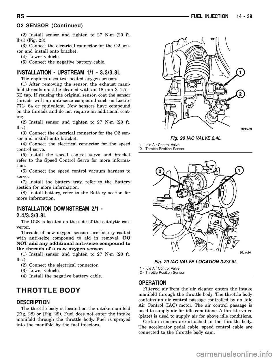
The throttle body is located on the intake manifold
(Fig. 28) or (Fig. 29). Fuel does not enter the intake
manifold through the throttle body. Fuel is sprayed
into the manifold by the fuel injectors.
OPERATION
Filtered air from the air cleaner enters the intake
manifold through the throttle body. The throttle body
contains an air control passage controlled by an Idle
Air Control (IAC) motor. The air control passage is
used to supply air for idle conditions. A throttle valve
(plate) is used to supply air for above idle conditions.
Certain sensors are attached to the throttle body.
The accelerator pedal cable, speed control cable are
connected to the throttle body cam.
Fig. 28 IAC VALVE 2.4L
1 - Idle Air Control Valve
2 - Throttle Position Sensor
Fig. 29 IAC VALVE LOCATION 3.3/3.8L
1 - Idle Air Control Valve
2 - Throttle Position Sensor
RSFUEL INJECTION14-39
O2 SENSOR (Continued)
Page 2279 of 2339
The major non-monitored circuits are listed below
along with examples of failures modes that do not
directly cause the PCM to set a DTC, but for a sys-
tem that is monitored.
FUEL PRESSURE
The fuel pressure regulator controls fuel system
pressure. The PCM cannot detect a clogged fuel
pump inlet filter, clogged in-line fuel filter, or a
pinched fuel supply or return line. However, these
could result in a rich or lean condition causing the
PCM to store an oxygen sensor, fuel system, or mis-
fire diagnostic trouble code.
SECONDARY IGNITION CIRCUIT
The PCM cannot detect an inoperative ignition coil,
fouled or worn spark plugs, ignition cross firing, or
open spark plug cables. The misfire will however,
increase the oxygen content in the exhaust, deceiving
the PCM in to thinking the fuel system is too lean.
Also see misfire detection. There are DTC's that can
detect misfire and Ionization shorts in the secondary
ignition circuit, refer to the Powertrain Diagnostic
manual for more information
CYLINDER COMPRESSION
The PCM cannot detect uneven, low, or high engine
cylinder compression. Low compression lowers O2
content in the exhaust. Leading to fuel system, oxy-
gen sensor, or misfire detection fault.
EXHAUST SYSTEM
The PCM cannot detect a plugged, restricted or
leaking exhaust system. It may set a EGR (if
equipped) or Fuel system or O2S fault.
FUEL INJECTOR MECHANICAL MALFUNCTIONS
The PCM cannot determine if a fuel injector is
clogged, the needle is sticking or if the wrong injector
is installed. However, these could result in a rich or
lean condition causing the PCM to store a diagnostic
trouble code for either misfire, an oxygen sensor, or
the fuel system.
EXCESSIVE OIL CONSUMPTION
Although the PCM monitors engine exhaust oxygen
content when the system is in closed loop, it cannot
determine excessive oil consumption.
THROTTLE BODY AIR FLOW
The PCM cannot detect a clogged or restricted air
cleaner inlet or filter element.
VACUUM ASSIST
The PCM cannot detect leaks or restrictions in the
vacuum circuits of vacuum assisted engine control
system devices. However, these could cause the PCMto store a MAP sensor diagnostic trouble code and
cause a high idle condition.
PCM SYSTEM GROUND
The PCM cannot determine a poor system ground.
However, one or more diagnostic trouble codes may
be generated as a result of this condition. The mod-
ule should be mounted to the body at all times,
including when diagnostics are performed.
PCM CONNECTOR ENGAGEMENT
The PCM may not be able to determine spread or
damaged connector pins. However, it might store
diagnostic trouble codes as a result of spread connec-
tor pins.
DESCRIPTION - MONITORED SYSTEMS
There are new electronic circuit monitors that
check fuel, emission, engine and ignition perfor-
mance. These monitors use information from various
sensor circuits to indicate the overall operation of the
fuel, engine, ignition and emission systems and thus
the emissions performance of the vehicle.
The fuel, engine, ignition and emission systems
monitors do not indicate a specific component prob-
lem. They do indicate that there is an implied prob-
lem within one of the systems and that a specific
problem must be diagnosed.
If any of these monitors detect a problem affecting
vehicle emissions, the Malfunction Indicator (Check
Engine) Lamp will be illuminated. These monitors
generate Diagnostic Trouble Codes that can be dis-
played with the a scan tool.
The following is a list of the system monitors:
┬▓EGR Monitor (if equipped)
┬▓Misfire Monitor
┬▓Fuel System Monitor
┬▓Oxygen Sensor Monitor
┬▓Oxygen Sensor Heater Monitor
┬▓Catalyst Monitor
┬▓Evaporative System Leak Detection Monitor (if
equipped)
Following is a description of each system monitor,
and its DTC.
Refer to the appropriate Powertrain Diagnos-
tics Procedures manual for diagnostic proce-
dures.
OXYGEN SENSOR (O2S) MONITOR
Effective control of exhaust emissions is achieved
by an oxygen feedback system. The most important
element of the feedback system is the O2S. The O2S
is located in the exhaust path. Once it reaches oper-
ating temperatures of 300É to 350ÉC (572É to 662ÉF),
the sensor generates a voltage that is inversely pro-
portional to the amount of oxygen in the exhaust.
25 - 6 EMISSIONS CONTROLRS
EMISSIONS CONTROL (Continued)
Page 2281 of 2339

tion occurs such that the PCM cannot maintain the
optimum A/F ratio, then the MIL will be illuminated.
CATALYST MONITOR
To comply with clean air regulations, vehicles are
equipped with catalytic converters. These converters
reduce the emission of hydrocarbons, oxides of nitro-
gen and carbon monoxide.
Normal vehicle miles or engine misfire can cause a
catalyst to decay. A meltdown of the ceramic core can
cause a reduction of the exhaust passage. This can
increase vehicle emissions and deteriorate engine
performance, driveability and fuel economy.
The catalyst monitor uses dual oxygen sensors
(O2S's) to monitor the efficiency of the converter. The
dual O2S's strategy is based on the fact that as a cat-
alyst deteriorates, its oxygen storage capacity and its
efficiency are both reduced. By monitoring the oxy-
gen storage capacity of a catalyst, its efficiency can
be indirectly calculated. The upstream O2S is used to
detect the amount of oxygen in the exhaust gas
before the gas enters the catalytic converter. The
PCM calculates the A/F mixture from the output of
the O2S. A low voltage indicates high oxygen content
(lean mixture). A high voltage indicates a low content
of oxygen (rich mixture).
When the upstream O2S detects a lean condition,
there is an abundance of oxygen in the exhaust gas.
A functioning converter would store this oxygen so it
can use it for the oxidation of HC and CO. As the
converter absorbs the oxygen, there will be a lack of
oxygen downstream of the converter. The output of
the downstream O2S will indicate limited activity in
this condition.
As the converter loses the ability to store oxygen,
the condition can be detected from the behavior of
the downstream O2S. When the efficiency drops, no
chemical reaction takes place. This means the con-
centration of oxygen will be the same downstream as
upstream. The output voltage of the downstream
O2S copies the voltage of the upstream sensor. The
only difference is a time lag (seen by the PCM)
between the switching of the O2S's.
To monitor the system, the number of lean-to-rich
switches of upstream and downstream O2S's is
counted. The ratio of downstream switches to
upstream switches is used to determine whether the
catalyst is operating properly. An effective catalyst
will have fewer downstream switches than it has
upstream switches i.e., a ratio closer to zero. For a
totally ineffective catalyst, this ratio will be one-to-
one, indicating that no oxidation occurs in the device.
The system must be monitored so that when cata-
lyst efficiency deteriorates and exhaust emissions
increase to over the legal limit, the MIL (Check
Engine lamp) will be illuminated.NATURAL VACUUM LEAK DETECTION (NVLD) (if equipped)
The Natural Vacuum Leak Detection (NVLD) sys-
tem is the next generation evaporative leak detection
system that will first be used on vehicles equipped
with the Next Generation Controller (NGC). This
new system replaces the leak detection pump as the
method of evaporative system leak detection. This is
to detect a leak equivalent to a 0.0209(0.5 mm) hole.
This system has the capability to detect holes of this
size very dependably.
The basic leak detection theory employed with
NVLD is the9Gas Law9. This is to say that the pres-
sure in a sealed vessel will change if the temperature
of the gas in the vessel changes. The vessel will only
see this effect if it is indeed sealed. Even small leaks
will allow the pressure in the vessel to come to equi-
librium with the ambient pressure. In addition to the
detection of very small leaks, this system has the
capability of detecting medium as well as large evap-
orative system leaks.
The NVLD seals the canister vent during engine
off conditions. If the EVAP system has a leak of less
than the failure threshold, the evaporative system
will be pulled into a vacuum, either due to the cool
down from operating temperature or diurnal ambient
temperature cycling. The diurnal effect is considered
one of the primary contributors to the leak determi-
nation by this diagnostic. When the vacuum in the
system exceeds about 19H2O (0.25 KPA), a vacuum
switch closes. The switch closure sends a signal to
the NGC. The NGC, via appropriate logic strategies
(described below), utilizes the switch signal, or lack
thereof, to make a determination of whether a leak is
present.
The NVLD device is designed with a normally open
vacuum switch, a normally closed solenoid, and a
seal, which is actuated by both the solenoid and a
diaphragm. The NVLD is located on the atmospheric
vent side of the canister. The NVLD assembly may
be mounted on top of the canister outlet, or in-line
between the canister and atmospheric vent filter. The
normally open vacuum switch will close with about 19
H2O (0.25 KPA) vacuum in the evaporative system.
The diaphragm actuates the switch. This is above the
opening point of the fuel inlet check valve in the fill
tube so cap off leaks can be detected. Submerged fill
systems must have recirculation lines that do not
have the in-line normally closed check valve that pro-
tects the system from failed nozzle liquid ingestion,
in order to detect cap off conditions.
The normally closed valve in the NVLD is intended
to maintain the seal on the evaporative system dur-
ing the engine off condition. If vacuum in the evapo-
rative system exceeds 39to 69H2O (0.75 to 1.5 KPA),
the valve will be pulled off the seat, opening the seal.
This will protect the system from excessive vacuum
25 - 8 EMISSIONS CONTROLRS
EMISSIONS CONTROL (Continued)
Page 2290 of 2339

DIAGNOSIS AND TESTING - VEHICLE DOES
NOT FILL
CONDITION POSSIBLE CAUSES CORRECTION
Pre-Mature Nozzle Shut-Off Defective fuel tank assembly
components.Fill tube improperly installed
(sump)
Fill tube hose pinched.
Check valve stuck shut.
Control valve stuck shut.
Defective vapor/vent components. Vent line from control valve to
canister pinched.
Vent line from canister to vent
filter pinched.
Canister vent valve failure
(requires double failure,
plugged to NVLD and
atmosphere).
Leak detection pump failed
closed.
Leak detection pump filter
plugged.
On-Board diagnostics evaporative
system leak test just conducted.Canister vent valve vent
plugged to atmosphere.
Engine still running when
attempting to fill (System
designed not to fill).
Defective fill nozzle. Try another nozzle.
Fuel Spits Out Of Filler
Tube.During fill. See Pre-Mature Shut-Off.
At conclusion of fill. Defective fuel handling
component. (Check valve stuck
open).
Defective vapor/vent handling
component.
Defective fill nozzle.
RSEVAPORATIVE EMISSIONS25-17
ORVR (Continued)
Page 2302 of 2339

INDEX
ABS FASTENER TORQUE,SPECIFICATIONS ...................... 5-91
ABSORBER - DESCRIPTION, SHOCK .......2-36
ABSORBER - INSTALLATION, SHOCK ......2-38
ABSORBER - OPERATION, SHOCK ........2-36
ABSORBER - REMOVAL, SHOCK ..........2-36
ABSORBER (UPPER BUSHING) - ASSEMBLY, SHOCK .................... 2-37
ABSORBER (UPPER BUSHING) - DISASSEMBLY, SHOCK .................2-37
A/C CLUTCH BREAK-IN, STANDARD PROCEDURE ........................ 24-15
A/C COMPRESSOR CLUTCH COIL, DIAGNOSIS AND TESTING .............24-14
A/C COMPRESSOR CLUTCH RELAY - DESCRIPTION ....................... 24-18
A/C COMPRESSOR CLUTCH RELAY - INSTALLATION ....................... 24-19
A/C COMPRESSOR CLUTCH RELAY - OPERATION ......................... 24-18
A/C COMPRESSOR CLUTCH RELAY - REMOVAL .......................... 24-19
A/C COMPRESSOR CLUTCH/COIL - DESCRIPTION ....................... 24-13
A/C COMPRESSOR CLUTCH/COIL - OPERATION ......................... 24-13
A/C COMPRESSOR, DESCRIPTION .......24-72
A/C COMPRESSOR, INSTALLATION .......24-74
A/C COMPRESSOR MOUNTING BRACKET, 2.4L ENGINE ...........24-74,24-75
A/C COMPRESSOR NOISE DIAGNOSIS, DIAGNOSIS AND TESTING .............24-72
A/C COMPRESSOR, OPERATION .........24-72
A/C COMPRESSOR, REMOVAL ..........24-73
A/C CONDENSER - DESCRIPTION ........24-75
A/C CONDENSER - OPERATION ..........24-75
A/C COOL DOWN TEST, DIAGNOSIS AND TESTING ............................ 24-6
A/C DISCHARGE LINE - INSTALLATION . . . 24-80
A/C DISCHARGE LINE - REMOVAL .......24-79
A/C EVAPORATOR - DESCRIPTION . . 24-80,24-98
A/C EVAPORATOR - INSTALLATION ......24-81
A/C EVAPORATOR - OPERATION ....24-80,24-98
A/C EVAPORATOR - REMOVAL ..........24-81
A/C EVAPORATOR, INSTALLATION - REAR ............................. 24-100
A/C EVAPORATOR LINE EXTENSION, INSTALLATION - REAR ...............24-100
A/C EVAPORATOR LINE EXTENSION, REMOVAL - REAR .................... 24-99
A/C EVAPORATOR, REMOVAL - REAR .....24-98
A/C EXPANSION VALVE - DESCRIPTION . . 24-100
A/C EXPANSION VALVE - OPERATION ....24-100
A/C EXPANSION VALVE, DIAGNOSIS AND TESTING - FRONT .................... 24-82
A/C EXPANSION VALVE, DIAGNOSIS AND TESTING - REAR .................... 24-101
A/C HEATER CONTROL - DESCRIPTION . . . 24-19
A/C PERFORMANCE TEST, DIAGNOSIS AND TESTING ........................ 24-7
A/C PRESSURE TRANSDUCER - DESCRIPTION ....................... 24-20
A/C PRESSURE TRANSDUCER - OPERATION ......................... 24-20
A/C PRESSURE TRANSDUCER, DIAGNOSIS AND TESTING .............24-21
A/C SYSTEM - CAUTION ...............24-66
A/C SYSTEM, SPECIFICATIONS ..........24-11
A/C SYSTEM, WARNING ...............24-66
ACCELERATOR PEDAL - INSTALLATION . . . 14-28
ACCELERATOR PEDAL - REMOVAL .......14-28
ACCESSORY DRIVE BELT - DIAGNOSIS AND TESTING .........................7-7
ACCESSORY DRIVE BELT TENSION, SPECIFICATIONS .......................7-5
ACCUMULATOR - DESCRIPTION . . . 21-218,21-73
ACCUMULATOR - OPERATION ....21-218,21-73
A/C-HEATER CONTROL - DESCRIPTION . . . 24-33
A/C-HEATER CONTROL - INSTALLATION . . . 24-34
A/C-HEATER CONTROL - OPERATION .....24-33
A/C-HEATER CONTROL - REMOVAL ......24-33
A/C-HEATER CONTROL CALIBRATION, STANDARD PROCEDURE ...............24-19
ACTUATOR - DESCRIPTION, BLEND DOOR ........................ 24-22,24-34
ACTUATOR - DESCRIPTION, ENGAGE ......8N-9
ACTUATOR - DESCRIPTION, LATCH ......8N-13 ACTUATOR - DESCRIPTION, MODE
DOOR ............................. 24-29
ACTUATOR - DESCRIPTION, RECIRCULATION DOOR ................24-31
ACTUATOR - INSTALLATION, BLEND DOOR ........................ 24-22,24-35
ACTUATOR - INSTALLATION, ENGAGE ....8N-10
ACTUATOR - INSTALLATION, INSIDE HANDLE ............................ 23-27
ACTUATOR - INSTALLATION, LATCH .....8N-14
ACTUATOR - INSTALLATION, MODE DOOR ............................. 24-30
ACTUATOR - INSTALLATION, RECIRCULATION DOOR ................24-32
ACTUATOR - OPERATION, BLEND DOOR . . 24-22, 24-35
ACTUATOR - OPERATION, ENGAGE .......8N-9
ACTUATOR - OPERATION, LATCH ........8N-13
ACTUATOR - OPERATION, MODE DOOR . . . 24-29
ACTUATOR - OPERATION, RECIRCULATION DOOR ................24-31
ACTUATOR - REAR - DESCRIPTION, MODE DOOR ........................ 24-39
ACTUATOR - REAR - INSTALLATION, MODE DOOR ........................ 24-40
ACTUATOR - REAR - OPERATION, MODE DOOR ............................. 24-39
ACTUATOR - REAR - REMOVAL, MODE DOOR ............................. 24-39
ACTUATOR - REMOVAL, BLEND DOOR . . . 24-22, 24-35
ACTUATOR - REMOVAL, ENGAGE ..........8N-9
ACTUATOR - REMOVAL, INSIDE HANDLE . . 23-27
ACTUATOR - REMOVAL, LATCH .........8N-13
ACTUATOR - REMOVAL, MODE DOOR ....24-29
ACTUATOR - REMOVAL, RECIRCULATION DOOR ............................. 24-32
ADAPTER - INSTALLATION, FRONT DISC BRAKE CALIPER ...................... 5-31
ADAPTER - INSTALLATION, OIL FILTER . . . 9-142
ADAPTER - REMOVAL, FRONT DISC BRAKE CALIPER ...................... 5-31
ADAPTER - REMOVAL, OIL FILTER .......9-142
ADAPTIVE MEMORIES, OPERATION - FUEL CORRECTION OR ................14-24
ADDING ADDITIONAL COOLANT - STANDARD PROCEDURE .................7-4
ADDITIONAL COOLANT - STANDARD PROCEDURE, ADDING ...................7-4
ADHESIVE ATTACHED - INSTALLATION, EXTERIOR NAME PLATES ..............23-51
ADHESIVE ATTACHED - REMOVAL, EXTERIOR NAME PLATES ..............23-51
ADHESIVE LOCATIONS - FOLD-IN-FLOOR ONLY - SPECIFICATIONS,
STRUCTURAL ...................... 23-228
ADHESIVE LOCATIONS - SPECIFICATIONS, STRUCTURAL ........23-218
ADJUSTABLE - INSTALLATION, PEDALS ....5-43
ADJUSTABLE - REMOVAL, PEDALS .......5-40
ADJUSTABLE PEDALS SWITCH - INSTALLATION ........................ 5-11
ADJUSTABLE PEDALS SWITCH - REMOVAL ........................... 5-11
ADJUSTE R-BOR C-PILLAR -
INSTALLATION, SEAT BELT HEIGHT ......8O-38
ADJUSTE R-BOR C-PILLAR -
REMOVAL, SEAT BELT HEIGHT ..........8O-38
ADJUSTER - DIAGNOSIS AND TESTING, DRUM BRAKE AUTOMATIC ..............5-14
ADJUSTER - INSTALLATION, FRONT SEAT TRACK MANUAL ...............23-126
ADJUSTER - INSTALLATION, FRONT SEAT TRACK POWER ................23-124
ADJUSTER - REMOVAL, FRONT SEAT TRACK MANUAL .................... 23-125
ADJUSTER - REMOVAL, FRONT SEAT TRACK POWER ..................... 23-124
ADJUSTER KNOB - INSTALLATION, SEAT BELT HEIGHT ....................... 8O-38
ADJUSTER KNOB - REMOVAL, SEAT BELT HEIGHT ....................... 8O-38
ADJUSTER NOISE DIAGNOSIS - DIAGNOSIS AND TESTING, HYDRAULIC
LASH ............................... 9-34
ADJUSTER TENSION RELEASE - STANDARD PROCEDURE, PARKING
BRAKE AUTOMATIC .................... 5-63ADJUSTER TENSION RESET -
STANDARD PROCEDURE, PARKING
BRAKE AUTOMATIC .................... 5-64
ADJUSTER/MANUAL - OCS - INSTALLATION, FRONT SEAT TRACK ....23-128
ADJUSTER/MANUAL - OCS - REMOVAL, FRONT SEAT TRACK .................23-126
ADJUSTER/POWER - OCS - INSTALLATION, FRONT SEAT TRACK ....23-125
ADJUSTER/POWER - OCS - REMOVAL, FRONT SEAT TRACK .................23-124
ADJUSTERS - INSTALLATION, HYDRAULIC LASH ..................... 9-35
ADJUSTERS - REMOVAL, HYDRAULIC LASH ............................... 9-35
AERATION - DIAGNOSIS AND TESTING, COOLING SYSTEM .....................7-4
AFTER AN AIRBAG DEPLOYMENT - STANDARD PROCEDURE, SERVICE .......8O-7
AIR CLEANER ELEMENT - INSTALLATION . 9-101, 9-24
AIR CLEANER ELEMENT - REMOVAL . 9-101,9-24
AIR CLEANER HOUSING - INSTALLATION . 9-102, 9-25
AIR CLEANER HOUSING - REMOVAL . 9-101,9-25
AIR CONDITIONER, DESCRIPTION - HEATER ............................. 24-1
AIR CONDITIONER, OPERATION - HEATER ............................. 24-4
AIR CONTROL MOTOR - DESCRIPTION, IDLE ............................... 14-33
AIR CONTROL MOTOR - INSTALLATION, IDLE ............................... 14-33
AIR CONTROL MOTOR - OPERATION, IDLE ............................... 14-33
AIR CONTROL MOTOR - REMOVAL, IDLE . . 14-33
AIR EXHAUSTER - DESCRIPTION, REAR QUARTER PANEL/FENDER ..............23-59
AIR EXHAUSTER - INSTALLATION, REAR QUARTER PANEL/FENDER ..............23-60
AIR EXHAUSTER - REMOVAL, REAR QUARTER PANEL/FENDER ..............23-59
AIR FILTER - DESCRIPTION ............24-42
AIR FILTER - INSTALLATION ............24-43
AIR FILTER - REMOVAL ...............24-42
AIR GAP, SPECIFICATIONS - WHEEL SPEED SENSOR ....................... 5-91
AIR INTAKE PIPE - INSTALLATION ......24-115
AIR INTAKE PIPE - REMOVAL ..........24-115
AIR OUTLETS - DESCRIPTION .....24-43,24-56
AIR OUTLETS - INSTALLATION ..........24-56
AIR OUTLETS - REMOVAL .............24-56
AIR PRESSURE TESTS - DIAGNOSIS AND TESTING, CLUTCH ...........21-153,21-8
AIR TEMPERATURE SENSOR - DESCRIPTION, INLET .................14-34
AIRBAG - DESCRIPTION, CURTAIN .......8O-12
AIRBAG - DESCRIPTION, DRIVER ........8O-16
AIRBAG - DESCRIPTION, KNEE BLOCKER . 8O-22
AIRBAG - DESCRIPTION, PASSENGER ....8O-30
AIRBAG - INSTALLATION, CURTAIN ......8O-16
AIRBAG - INSTALLATION, DRIVER .......8O-18
AIRBAG - INSTALLATION, KNEE BLOCKER .......................... 8O-23
AIRBAG - INSTALLATION, PASSENGER . . . 8O-32
AIRBAG - OPERATION, CURTAIN ........8O-13
AIRBAG - OPERATION, DRIVER .........8O-16
AIRBAG - OPERATION, KNEE BLOCKER . . . 8O-22
AIRBAG - OPERATION, PASSENGER ......8O-30
AIRBAG - REMOVAL, CURTAIN ..........8O-14
AIRBAG - REMOVAL, DRIVER ...........8O-17
AIRBAG - REMOVAL, KNEE BLOCKER ....8O-23
AIRBAG - REMOVAL, PASSENGER .......8O-30
AIRBAG DEPLOYMENT - STANDARD PROCEDURE, SERVICE AFTER AN ........8O-7
AIRBAG DISABLED INDICATOR - DESCRIPTION, PASSENGER ............8O-33
AIRBAG DISABLED INDICATOR - INSTALLATION, PASSENGER ...........8O-34
AIRBAG DISABLED INDICATOR - OPERATION, PASSENGER ..............8O-33
AIRBAG DISABLED INDICATOR - REMOVAL, PASSENGER ...............8O-34
AIRBAG SYSTEM - DIAGNOSIS AND TESTING ............................ 8O-6
AIRBAGS - STANDARD PROCEDURE, HANDLING .......................... 8O-6
RS INDEX1
Description Group-Page Description Group-Page Description Group-Page