location CHRYSLER CARAVAN 2005 Service Manual
[x] Cancel search | Manufacturer: CHRYSLER, Model Year: 2005, Model line: CARAVAN, Model: CHRYSLER CARAVAN 2005Pages: 2339, PDF Size: 59.69 MB
Page 2200 of 2339
(12) Gently flex the recirculation air door far down
enough to remove the blower motor and wheel from
the HVAC housing.
(13) Remove the blower motor and wheel from the
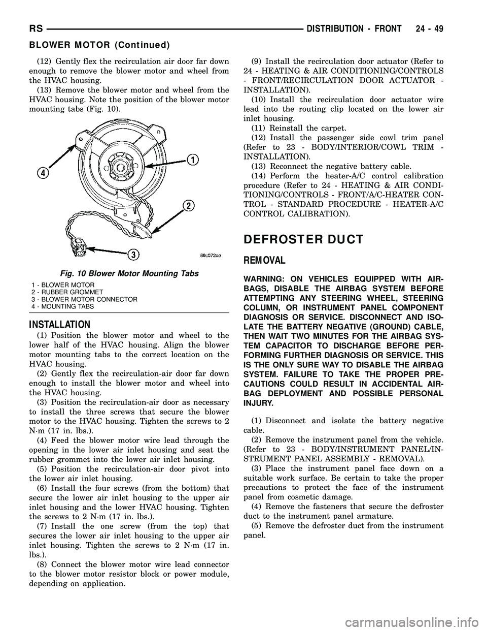
HVAC housing. Note the position of the blower motor
mounting tabs (Fig. 10).
INSTALLATION
(1) Position the blower motor and wheel to the
lower half of the HVAC housing. Align the blower
motor mounting tabs to the correct location on the
HVAC housing.
(2) Gently flex the recirculation-air door far down
enough to install the blower motor and wheel into
the HVAC housing.
(3) Position the recirculation-air door as necessary
to install the three screws that secure the blower
motor to the HVAC housing. Tighten the screws to 2
N´m (17 in. lbs.).
(4) Feed the blower motor wire lead through the
opening in the lower air inlet housing and seat the
rubber grommet into the lower air inlet housing.
(5) Position the recirculation-air door pivot into
the lower air inlet housing.
(6) Install the four screws (from the bottom) that
secure the lower air inlet housing to the upper air
inlet housing and the lower HVAC housing. Tighten
the screws to 2 N´m (17 in. lbs.).
(7) Install the one screw (from the top) that
secures the lower air inlet housing to the upper air
inlet housing. Tighten the screws to 2 N´m (17 in.
lbs.).
(8) Connect the blower motor wire lead connector
to the blower motor resistor block or power module,
depending on application.(9) Install the recirculation door actuator (Refer to
24 - HEATING & AIR CONDITIONING/CONTROLS
- FRONT/RECIRCULATION DOOR ACTUATOR -
INSTALLATION).
(10) Install the recirculation door actuator wire
lead into the routing clip located on the lower air
inlet housing.
(11) Reinstall the carpet.
(12) Install the passenger side cowl trim panel
(Refer to 23 - BODY/INTERIOR/COWL TRIM -
INSTALLATION).
(13) Reconnect the negative battery cable.
(14) Perform the heater-A/C control calibration
procedure (Refer to 24 - HEATING & AIR CONDI-
TIONING/CONTROLS - FRONT/A/C-HEATER CON-
TROL - STANDARD PROCEDURE - HEATER-A/C
CONTROL CALIBRATION).
DEFROSTER DUCT
REMOVAL
WARNING: ON VEHICLES EQUIPPED WITH AIR-
BAGS, DISABLE THE AIRBAG SYSTEM BEFORE
ATTEMPTING ANY STEERING WHEEL, STEERING
COLUMN, OR INSTRUMENT PANEL COMPONENT
DIAGNOSIS OR SERVICE. DISCONNECT AND ISO-
LATE THE BATTERY NEGATIVE (GROUND) CABLE,
THEN WAIT TWO MINUTES FOR THE AIRBAG SYS-
TEM CAPACITOR TO DISCHARGE BEFORE PER-
FORMING FURTHER DIAGNOSIS OR SERVICE. THIS
IS THE ONLY SURE WAY TO DISABLE THE AIRBAG
SYSTEM. FAILURE TO TAKE THE PROPER PRE-
CAUTIONS COULD RESULT IN ACCIDENTAL AIR-
BAG DEPLOYMENT AND POSSIBLE PERSONAL
INJURY.
(1) Disconnect and isolate the battery negative
cable.
(2) Remove the instrument panel from the vehicle.
(Refer to 23 - BODY/INSTRUMENT PANEL/IN-
STRUMENT PANEL ASSEMBLY - REMOVAL).
(3) Place the instrument panel face down on a
suitable work surface. Be certain to take the proper
precautions to protect the face of the instrument
panel from cosmetic damage.
(4) Remove the fasteners that secure the defroster
duct to the instrument panel armature.
(5) Remove the defroster duct from the instrument
panel.Fig. 10 Blower Motor Mounting Tabs
1 - BLOWER MOTOR
2 - RUBBER GROMMET
3 - BLOWER MOTOR CONNECTOR
4 - MOUNTING TABS
RSDISTRIBUTION - FRONT24-49
BLOWER MOTOR (Continued)
Page 2207 of 2339
DISTRIBUTION - REAR
TABLE OF CONTENTS
page page
AIR OUTLETS
DESCRIPTION.........................56
REMOVAL.............................56
INSTALLATION.........................56
DISTRIBUTION DUCT
REMOVAL.............................57
INSTALLATION.........................57
BLOWER MOTOR
DESCRIPTION.........................57
OPERATION...........................57DIAGNOSIS AND TESTING
REAR BLOWER MOTOR................58
REMOVAL.............................58
INSTALLATION.........................60
HVAC HOUSING
REMOVAL.............................60
INSTALLATION.........................62
REAR FLOOR HEAT DUCT
REMOVAL.............................63
INSTALLATION.........................63
AIR OUTLETS
DESCRIPTION
Based upon the system mode selected, conditioned
air can exit the rear HVAC housing through one or a
combination of the two main housing outlets: air con-
ditioner, or heater. Once the conditioned air exits the
unit housing, it is directed through molded plastic
ducts to the various outlets in the vehicle interior.
These outlets and their locations are as follows:
²Floor Outlets- Three floor outlets with fixed
vanes are located in the right quarter trim panel,
near the floor. These outlets distribute air from the
rear floor heat duct to the intermediate and rear seat
occupants. The floor outlets are integral to the right
quarter trim panel and, if faulty or damaged, the
quarter trim panel must be replaced.
²Overhead Outlets- Four (two right side and
two left side) fully adjustable outlets along the roof
rails distribute air from the rear distribution duct
and the headliner ducts to the intermediate and rear
seat occupants. The headliner ducts are integral to
the headliner panel. Each overhead outlet is housed
in a headliner bezel. The two forward headliner
bezels also feature a courtesy lamp, a fold-away coat
hook, and a fold-away assist handle. The overhead
outlets can be removed from the headliner bezels
individually for service replacement.
REMOVAL
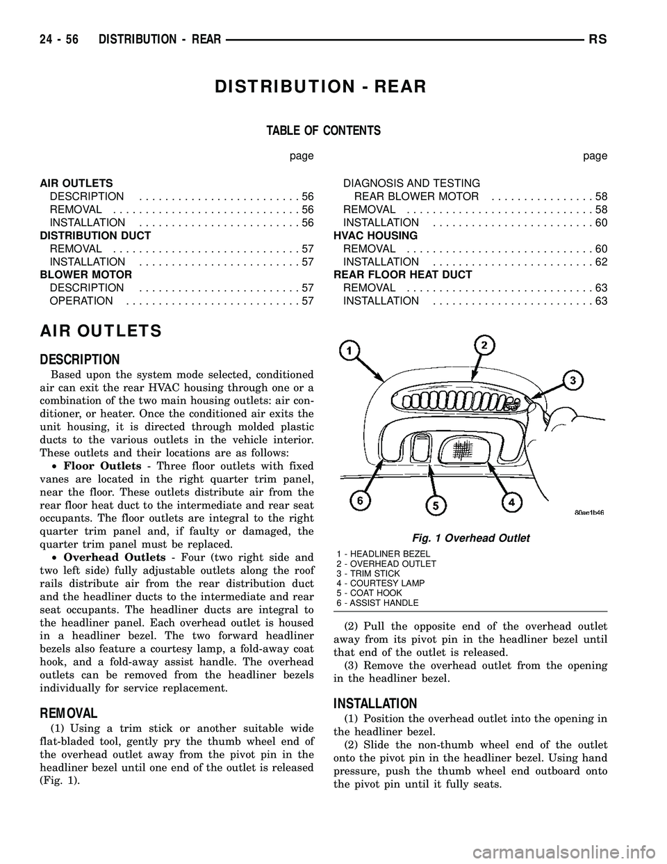
(1) Using a trim stick or another suitable wide
flat-bladed tool, gently pry the thumb wheel end of
the overhead outlet away from the pivot pin in the
headliner bezel until one end of the outlet is released
(Fig. 1).(2) Pull the opposite end of the overhead outlet
away from its pivot pin in the headliner bezel until
that end of the outlet is released.
(3) Remove the overhead outlet from the opening
in the headliner bezel.
INSTALLATION
(1) Position the overhead outlet into the opening in
the headliner bezel.
(2) Slide the non-thumb wheel end of the outlet
onto the pivot pin in the headliner bezel. Using hand
pressure, push the thumb wheel end outboard onto
the pivot pin until it fully seats.
Fig. 1 Overhead Outlet
1 - HEADLINER BEZEL
2 - OVERHEAD OUTLET
3 - TRIM STICK
4 - COURTESY LAMP
5 - COAT HOOK
6 - ASSIST HANDLE
24 - 56 DISTRIBUTION - REARRS
Page 2209 of 2339
DIAGNOSIS AND TESTING
REAR BLOWER MOTOR
BLOWER MOTOR INOPERATIVE
For circuit descriptions and diagrams, refer to the
appropriate wiring information. The wiring informa-
tion includes wiring, diagrams, proper wire and con-
nector repair procedures, further details on wire
harness routing and retention, as well as pin-out and
location views for the various wire harness connec-
tors, splices and grounds.
BLOWER MOTOR ELECTRICAL DIAGNOSIS
(1) Check the fuse (Fuse 12 - 25 ampere) in the
Integrated Power Module (IPM). If OK, go to Step 2.
If not OK, repair the shorted circuit or component as
required and replace the faulty fuse.
(2) Turn the ignition switch to the On position. Be
certain that the rear A/C-heater control power is
turned on. Check for battery voltage at the fuse
(Fuse 12 - 25 ampere) in the IPM. If OK, go to Step
3. If not OK, check the rear blower motor relay.
(3) Turn the ignition switch to the Off position.
Disconnect and isolate the battery negative cable.
Disconnect the rear HVAC wire harness connector
from the rear blower motor resistor block (Manual
Temperature Control) or the rear blower motor power
module (Automatic Temperature Control). Reconnect
the battery negative cable. Turn the ignition switch
to the On position. Be certain that the rear A/C-
heater control power is turned on. Check for battery
voltage at the fused rear blower motor relay output
circuit cavity of the rear HVAC wire harness connec-
tor for the rear blower motor resistor block (MTC) or
the rear blower motor power module (ATC). If OK, go
to Step 4. If not OK, repair the open fused front
blower motor relay output circuit to the IPM as
required.
(4) Turn the ignition switch to the Off position.
Disconnect and isolate the battery negative cable.Disconnect the rear blower motor pigtail wire connec-
tor from the rear HVAC wire harness (MTC) or the
rear blower power module (ATC). Use jumper wires
to connect a battery and ground feeds to the blower
motor pigtail wire connector. The rear blower motor
should operate. If OK with MTC, proceed to diagno-
sis of the rear blower motor resistor block (Refer to
24 - HEATING & AIR CONDITIONING/CONTROLS
- REAR/BLOWER MOTOR RESISTOR - DIAGNOSIS
AND TESTING). If OK with ATC, use a DRBIII scan
tool to diagnose the rear blower motor power module.
Refer to the appropriate diagnostic information. If
not OK with MTC or ATC, replace the faulty rear
blower motor.
BLOWER MOTOR NOISE OR VIBRATION
Refer to the Blower Motor Noise/Vibration Diagno-
sis chart for basic checks of the blower motor when a
vibration or noise is present (Fig. 3).
REMOVAL
WARNING: REFER TO THE APPLICABLE WARN-
INGS AND CAUTIONS FOR THIS SYSTEM BEFORE
PERFORMING THE FOLLOWING OPERATION (Refer
to 24 - HEATING & AIR CONDITIONING/PLUMBING -
WARNING) and (Refer to 24 - HEATING & AIR CON-
DITIONING/PLUMBING - CAUTION).
(1) Remove the rear HVAC housing from the vehi-
cle (Refer to 24 - HEATING & AIR CONDITIONING/
DISTRIBUTION/HVAC HOUSING - REMOVAL).
(2) Disconnect the rear blower motor pigtail wire
connector.
NOTE: With the Manual Temperature Control sys-
tem, the blower motor pigtail wire is connected to a
take out and connector of the rear HVAC wire har-
ness. With the Automatic Temperature Control sys-
tem , the blower pigtail wire is connected to a
receptacle on the blower motor power module.
24 - 58 DISTRIBUTION - REARRS
BLOWER MOTOR (Continued)
Page 2218 of 2339
DIAGNOSIS AND TESTING
REFRIGERANT SYSTEM LEAKS
WARNING: R-134a SERVICE EQUIPMENT OR VEHI-
CLE A/C SYSTEM SHOULD NOT BE PRESSURE
TESTED OR LEAK TESTED WITH COMPRESSED
AIR. MIXTURE OF AIR and R-134a CAN BE COMBUS-
TIBLE AT ELEVATED PRESSURES. THESE MIX-
TURES ARE POTENTIALLY DANGEROUS AND MAY
RESULT IN FIRE OR EXPLOSION CAUSING INJURY
OR PROPERTY DAMAGE.
AVOID BREATHING A/C REFRIGERANT AND LUBRI-
CANT VAPOR OR MIST. EXPOSURE MAY IRRITATE
EYES, NOSE AND THROAT. USE ONLY APPROVED
SERVICE EQUIPMENT MEETING SAE REQUIRE-
MENTS TO DISCHARGE R-134a SYSTEM. IF ACCI-
DENTAL SYSTEM DISCHARGE OCCURS, VENTILATE
WORK AREA BEFORE RESUMING SERVICE.
If the A/C system is not cooling properly, determine
if the refrigerant system is fully charged with R-134a
(Refer to 24 - HEATING & AIR CONDITIONING/
PLUMBING - FRONT/REFRIGERANT - DIAGNO-
SIS AND TESTING - REFRIGERANT SYSTEM
CHARGE LEVEL). If while performing this test A/C
liquid line pressure is less than 345 kPa (50 psi) pro-
ceed to System Empty procedure. If liquid line pres-
sure is greater than 345 kPa (50 psi) proceed to
System Low procedure. If the refrigerant system is
empty or low in refrigerant charge, a leak at any line
fitting or component seal is likely. A review of the fit-
tings, lines and components for oily residue is an
indication of the leak location.
To detect a leak in the refrigerant system, perform
one of the following procedures as indicated by the
results of the refrigerant system charge level test.
SYSTEM EMPTY
(1) Evacuate the refrigerant system to the lowest
degree of vacuum possible (approx. 28 in Hg.) (Refer
to 24 - HEATING & AIR CONDITIONING/PLUMB-
ING - FRONT/REFRIGERANT - STANDARD PRO-
CEDURE - REFRIGERANT SYSTEM EVACUATE).
Determine if the system holds a vacuum for 15 min-
utes. If vacuum is held, a leak is probably not
present. If system will not maintain vacuum level,
proceed with this procedure.
(2) Prepare a 0.284 Kg. (10 oz.) refrigerant charge
to be injected into the system.
(3) Connect and dispense 0.284 Kg. (10 oz.) of
refrigerant into the evacuated refrigerant system
(Refer to 24 - HEATING & AIR CONDITIONING/
PLUMBING - FRONT/REFRIGERANT - STANDARD
PROCEDURE - REFRIGERANT SYSTEM CHARGE).
(4) Proceed to the SYSTEM LOW procedures.SYSTEM LOW
(1) Position the vehicle in a wind-free work area.
This will aid in detecting small leaks.
(2) Bring the refrigerant system up to operating
temperature and pressure. This is done by allowing
the engine to run for five minutes with the system
set to the following:
²Transaxle in Park
²Engine idling
²Rear A/C Off (if equipped)
²A/C controls set to 100 percent outside air
²Blower switch in the highest speed position
²A/C in the ON position
²Front windows open
CAUTION: A leak detector designed for R-12 refrig-
erant (only) will not detect leaks in a R-134a refrig-
erant system.
(3) Shut off the vehicle and wait 2 to 7 minutes.
Then use an Electronic Leak Detector that is
designed to detect R-134a type refrigerant and search
for leaks. Fittings, lines, or components that appear
to be oily usually indicates a refrigerant leak. To
inspect the evaporator core for leaks, insert the leak
detector probe into the drain tube opening or a heat
duct. A R-134a dye is available to aid in leak detec-
tion, use only DaimlerChrysler approved refrigerant
dye.
SYSTEM CHARGE LEVEL TEST
WARNING: REFER TO THE APPLICABLE WARN-
INGS AND CAUTIONS FOR THIS SYSTEM BEFORE
PERFORMING THE FOLLOWING OPERATION (Refer
to 24 - HEATING & AIR CONDITIONING/PLUMBING -
FRONT - WARNING - A/C PLUMBING) and (Refer to
24 - HEATING & AIR CONDITIONING/PLUMBING -
FRONT - CAUTION - A/C PLUMBING).
NOTE: Always refer to the underhood HVAC Speci-
fication Label for the refrigerant fill specification of
the vehicle being serviced.
The procedure that follows should be used to deter-
mine whether the refrigerant system contains the
proper refrigerant charge. Symptoms of an improper
refrigerant charge (low) include: poor air conditioner
performance, fog emitted from the air conditioner
outlets, a hissing sound from the expansion valve/
evaporator area. There are two different methods
with which the refrigerant charge level may be
tested:
1. Using a DRBIIItscan tool, a thermocouple and
the Charge Determination Chart (Fig. 1). Refer to
the appropriate diagnostic information.
RSPLUMBING - FRONT24-67
PLUMBING - FRONT (Continued)
Page 2227 of 2339
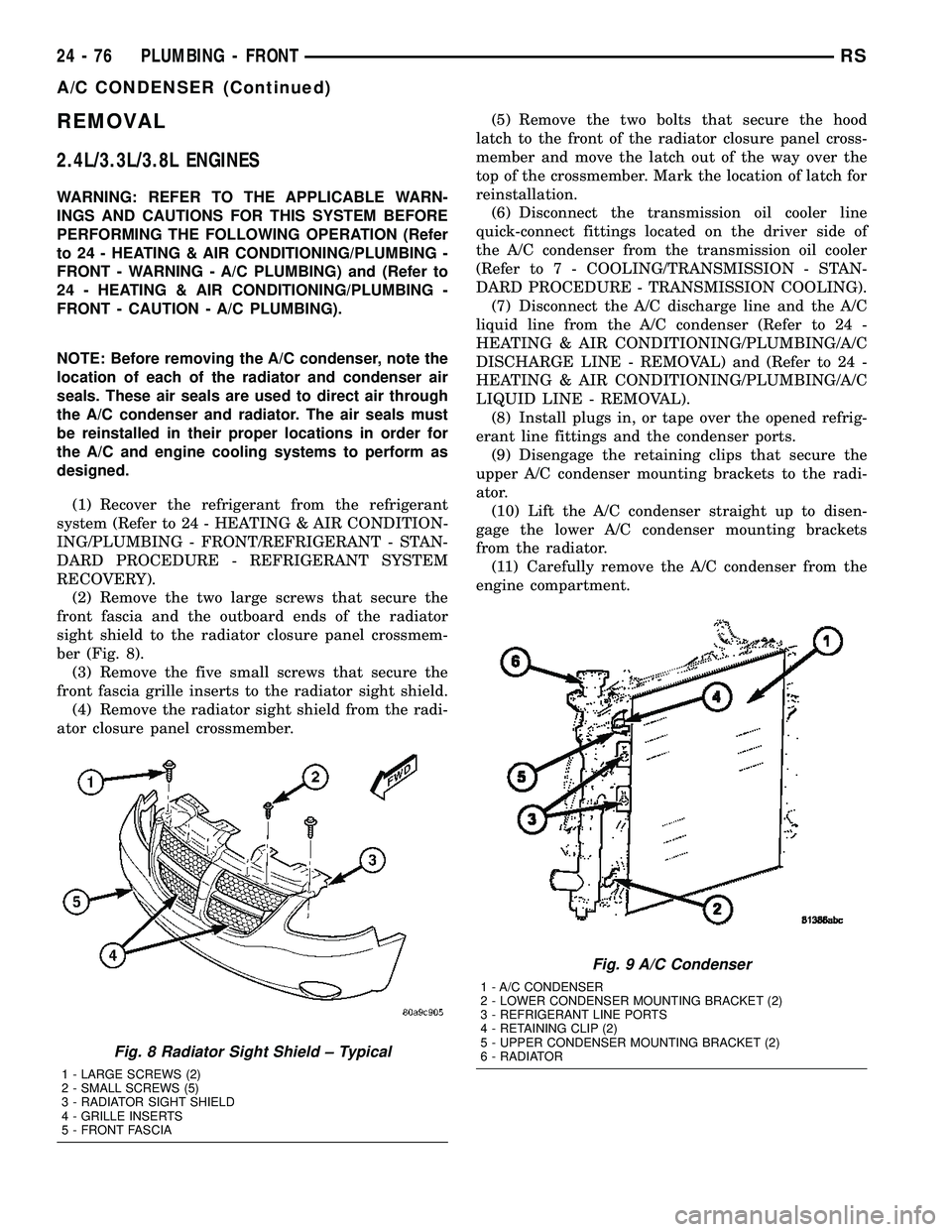
REMOVAL
2.4L/3.3L/3.8L ENGINES
WARNING: REFER TO THE APPLICABLE WARN-
INGS AND CAUTIONS FOR THIS SYSTEM BEFORE
PERFORMING THE FOLLOWING OPERATION (Refer
to 24 - HEATING & AIR CONDITIONING/PLUMBING -
FRONT - WARNING - A/C PLUMBING) and (Refer to
24 - HEATING & AIR CONDITIONING/PLUMBING -
FRONT - CAUTION - A/C PLUMBING).
NOTE: Before removing the A/C condenser, note the
location of each of the radiator and condenser air
seals. These air seals are used to direct air through
the A/C condenser and radiator. The air seals must
be reinstalled in their proper locations in order for
the A/C and engine cooling systems to perform as
designed.
(1) Recover the refrigerant from the refrigerant
system (Refer to 24 - HEATING & AIR CONDITION-
ING/PLUMBING - FRONT/REFRIGERANT - STAN-
DARD PROCEDURE - REFRIGERANT SYSTEM
RECOVERY).
(2) Remove the two large screws that secure the
front fascia and the outboard ends of the radiator
sight shield to the radiator closure panel crossmem-
ber (Fig. 8).
(3) Remove the five small screws that secure the
front fascia grille inserts to the radiator sight shield.
(4) Remove the radiator sight shield from the radi-
ator closure panel crossmember.(5) Remove the two bolts that secure the hood
latch to the front of the radiator closure panel cross-
member and move the latch out of the way over the
top of the crossmember. Mark the location of latch for
reinstallation.
(6) Disconnect the transmission oil cooler line
quick-connect fittings located on the driver side of
the A/C condenser from the transmission oil cooler
(Refer to 7 - COOLING/TRANSMISSION - STAN-
DARD PROCEDURE - TRANSMISSION COOLING).
(7) Disconnect the A/C discharge line and the A/C
liquid line from the A/C condenser (Refer to 24 -
HEATING & AIR CONDITIONING/PLUMBING/A/C
DISCHARGE LINE - REMOVAL) and (Refer to 24 -
HEATING & AIR CONDITIONING/PLUMBING/A/C
LIQUID LINE - REMOVAL).
(8) Install plugs in, or tape over the opened refrig-
erant line fittings and the condenser ports.
(9) Disengage the retaining clips that secure the
upper A/C condenser mounting brackets to the radi-
ator.
(10) Lift the A/C condenser straight up to disen-
gage the lower A/C condenser mounting brackets
from the radiator.
(11) Carefully remove the A/C condenser from the
engine compartment.
Fig. 8 Radiator Sight Shield ± Typical
1 - LARGE SCREWS (2)
2 - SMALL SCREWS (5)
3 - RADIATOR SIGHT SHIELD
4 - GRILLE INSERTS
5 - FRONT FASCIA
Fig. 9 A/C Condenser
1 - A/C CONDENSER
2 - LOWER CONDENSER MOUNTING BRACKET (2)
3 - REFRIGERANT LINE PORTS
4 - RETAINING CLIP (2)
5 - UPPER CONDENSER MOUNTING BRACKET (2)
6 - RADIATOR
24 - 76 PLUMBING - FRONTRS
A/C CONDENSER (Continued)
Page 2228 of 2339
2.5L/2.8L DIESEL ENGINES
WARNING: REFER TO THE APPLICABLE WARN-
INGS AND CAUTIONS FOR THIS SYSTEM BEFORE
PERFORMING THE FOLLOWING OPERATION (Refer
to 24 - HEATING & AIR CONDITIONING/PLUMBING -
FRONT - WARNING - A/C PLUMBING) and (Refer to
24 - HEATING & AIR CONDITIONING/PLUMBING -
FRONT - CAUTION - A/C PLUMBING).
NOTE: Before removing the A/C condenser, note the
location of each of the radiator and condenser air
seals. These air seals are used to direct air through
the A/C condenser and radiator. The air seals must
be reinstalled in their proper locations in order for
the A/C and engine cooling systems to perform as
designed.
(1) Recover the refrigerant from the refrigerant
system (Refer to 24 - HEATING & AIR CONDITION-
ING/PLUMBING - FRONT/REFRIGERANT - STAN-
DARD PROCEDURE - REFRIGERANT SYSTEM
RECOVERY).
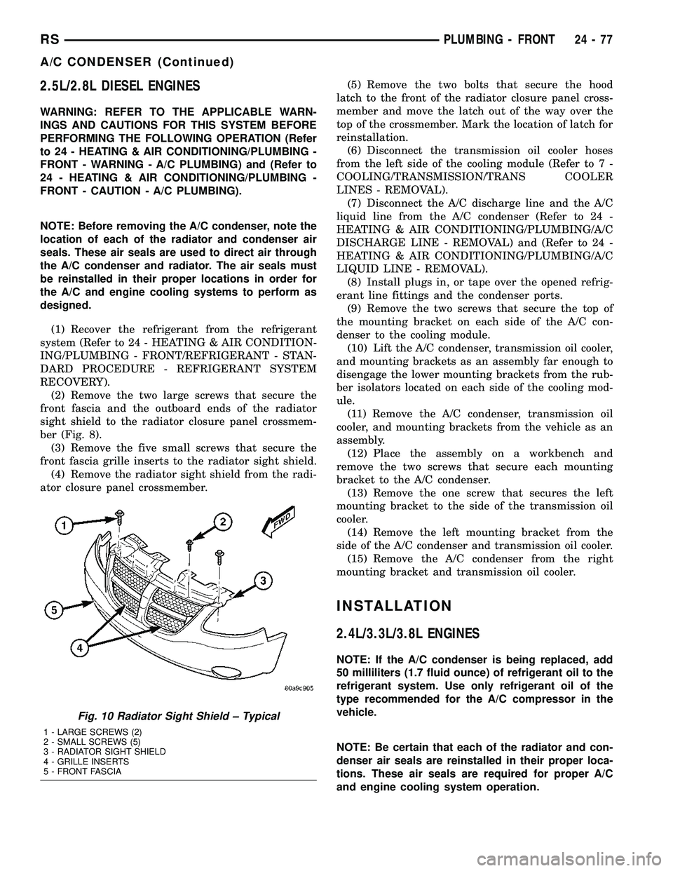
(2) Remove the two large screws that secure the
front fascia and the outboard ends of the radiator
sight shield to the radiator closure panel crossmem-
ber (Fig. 8).
(3) Remove the five small screws that secure the
front fascia grille inserts to the radiator sight shield.
(4) Remove the radiator sight shield from the radi-
ator closure panel crossmember.(5) Remove the two bolts that secure the hood
latch to the front of the radiator closure panel cross-
member and move the latch out of the way over the
top of the crossmember. Mark the location of latch for
reinstallation.
(6) Disconnect the transmission oil cooler hoses
from the left side of the cooling module (Refer to 7 -
COOLING/TRANSMISSION/TRANS COOLER
LINES - REMOVAL).
(7) Disconnect the A/C discharge line and the A/C
liquid line from the A/C condenser (Refer to 24 -
HEATING & AIR CONDITIONING/PLUMBING/A/C
DISCHARGE LINE - REMOVAL) and (Refer to 24 -
HEATING & AIR CONDITIONING/PLUMBING/A/C
LIQUID LINE - REMOVAL).
(8) Install plugs in, or tape over the opened refrig-
erant line fittings and the condenser ports.
(9) Remove the two screws that secure the top of
the mounting bracket on each side of the A/C con-
denser to the cooling module.
(10) Lift the A/C condenser, transmission oil cooler,
and mounting brackets as an assembly far enough to
disengage the lower mounting brackets from the rub-
ber isolators located on each side of the cooling mod-
ule.
(11) Remove the A/C condenser, transmission oil
cooler, and mounting brackets from the vehicle as an
assembly.
(12) Place the assembly on a workbench and
remove the two screws that secure each mounting
bracket to the A/C condenser.
(13) Remove the one screw that secures the left
mounting bracket to the side of the transmission oil
cooler.
(14) Remove the left mounting bracket from the
side of the A/C condenser and transmission oil cooler.
(15) Remove the A/C condenser from the right
mounting bracket and transmission oil cooler.
INSTALLATION
2.4L/3.3L/3.8L ENGINES
NOTE: If the A/C condenser is being replaced, add
50 milliliters (1.7 fluid ounce) of refrigerant oil to the
refrigerant system. Use only refrigerant oil of the
type recommended for the A/C compressor in the
vehicle.
NOTE: Be certain that each of the radiator and con-
denser air seals are reinstalled in their proper loca-
tions. These air seals are required for proper A/C
and engine cooling system operation.
Fig. 10 Radiator Sight Shield ± Typical
1 - LARGE SCREWS (2)
2 - SMALL SCREWS (5)
3 - RADIATOR SIGHT SHIELD
4 - GRILLE INSERTS
5 - FRONT FASCIA
RSPLUMBING - FRONT24-77
A/C CONDENSER (Continued)
Page 2237 of 2339
(3) Align the engine compartment ends of both
heater core tubes with the openings in the dash
panel seal and push them simultaneously forward
through the seal far enough to engage the heater
core ends of the tubes with the heater core supply
and return ports.
(4) Position both heater core tubes and the sealing
plate simultaneously to the heater core supply and
return ports.
NOTE: The heater core tubes each have a slot that
must be indexed to a location tab within each of the
heater core ports. Adjust the position of the tubes
as required so that the sealing plate fits flush
against the heater core supply and return ports,
which indicates that the tubes are properly indexed.
(5) Index both heater core tubes to the heater core
ports.
(6) Install the screw that secures the heater core
tube sealing plate to the heater core supply and
return ports. Tighten the screw to 3 N´m (27 in. lbs.).
(7) Install the silencer under the driver side end of
the instrument panel.
(8) Connect the heater hoses to the heater hose
tubes (Refer to 24 - HEATING & AIR CONDITION-
ING/PLUMBING/HEATER INLET HOSE - INSTAL-
LATION) and(Refer to 24 - HEATING & AIR
CONDITIONING/PLUMBING/HEATER RETURN
HOSE - INSTALLATION).
(9) Reconnect the battery negative cable.
(10) Refill the engine cooling system (Refer to 7 -
COOLING - STANDARD PROCEDURE - COOLING
SYSTEM REFILL).
FRONT HEATER CORE
(1) While pushing the brake pedal downward and
pulling the accelerator pedal upward far enough for
clearance, slide the heater core into the distribution
housing.
(2) Install the two screws that secure the heater
core mounting plate to the distribution housing.
Tighten the screws to 2 N´m (17 in. lbs.).(3) Install the heater core tubes (Refer to 24 -
HEATING & AIR CONDITIONING/PLUMBING/
HEATER CORE - INSTALLATION).
(4) Reconnect the power brake booster input rod
(push rod) to the pin on the brake pedal arm (Refer
to 5 - BRAKES/HYDRAULIC/MECHANICAL/
POWER BRAKE BOOSTER - INSTALLATION).
(5) Reinstall the brake lamp switch into its mount-
ing bracket (Refer to 8 - ELECTRICAL/LAMPS/
LIGHTING - EXTERIOR/BRAKE LAMP SWITCH -
INSTALLATION).
(6) Reinstall the silencer boot around the base of
the lower steering shaft on the dash panel.
(7) Reconnect the battery negative cable.
(8) Refill the engine cooling system (Refer to 7 -
COOLING - STANDARD PROCEDURE - COOLING
SYSTEM REFILL).
(9) Operate system for two thermostat cycles to
assure the elimination of any air that may be
trapped within the cooling system.
HEATER INLET HOSE
REMOVAL
WARNING: REFER TO THE APPLICABLE WARN-
INGS AND CAUTIONS FOR THIS SYSTEM BEFORE
PERFORMING THE FOLLOWING OPERATION (Refer
to 24 - HEATING & AIR CONDITIONING/PLUMBING -
WARNING).
NOTE: The heater inlet hose is constructed from
formed steel tubing and rubber hoses. Depending
on application, the ends are secured to the heater
core, engine oil cooler or the engine by spring ten-
sion clamps.
(1) Drain the engine cooling system (Refer to 7 -
COOLING - STANDARD PROCEDURE - COOLING
SYSTEM DRAIN).
24 - 86 PLUMBING - FRONTRS
HEATER CORE (Continued)
Page 2267 of 2339
(6) Refill the engine cooling system (Refer to 7 -
COOLING - STANDARD PROCEDURE).
(7) Verify function of the cabin heater.
EXHAUST TUBE
REMOVAL
WARNING: THERE IS A POTENTIAL DANGER OF
SKIN BURNS AS THE SUPPLEMENTAL CABIN
HEATER AND ITS COMPONENTS MAY BE VERY
HOT. MAKE SURE THE CABIN HEATER IS
ALLOWED TO COOL DOWN BEFORE ANY SERVICE
WORK ON THE CABIN HEATER SYSTEM IS
ATTEMPTED.
(1) Raise and support the vehicle. Take note of the
location of the flexible section of the cabin heater
exhaust tube.
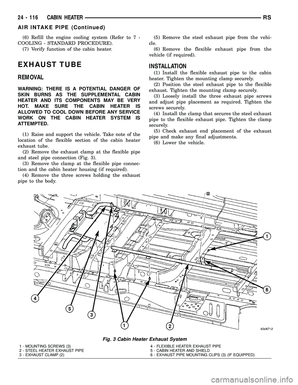
(2) Remove the exhaust clamp at the flexible pipe
and steel pipe connection (Fig. 3).
(3) Remove the clamp at the flexible pipe connec-
tion and the cabin heater housing (if required).
(4) Remove the three screws holding the exhaust
pipe to the body.(5) Remove the steel exhaust pipe from the vehi-
cle.
(6) Remove the flexible exhaust pipe from the
vehicle (if required).
INSTALLATION
(1) Install the flexible exhaust pipe to the cabin
heater. Tighten the mounting clamp securely.
(2) Position the steel exhaust pipe to the flexible
exhaust. Tighten the mounting clamp securely.
(3) Loosely install the three exhaust pipe screws
and adjust pipe placement as required. Tighten the
screws securely.
(4) Install the clamp that secures the steel exhaust
pipe to the flexible exhaust pipe. Tighten the clamp
securely.
(5) Check exhaust end placement of the exhaust
pipe and make any final adjustments.
(6) Lower the vehicle.
Fig. 3 Cabin Heater Exhaust System
1 - MOUNTING SCREWS (3)
2 - STEEL HEATER EXHAUST PIPE
3 - EXHAUST CLAMP (2)4 - FLEXIBLE HEATER EXHAUST PIPE
5 - CABIN HEATER AND SHIELD
6 - EXHAUST PIPE MOUNTING CLIPS (3) (IF EQUIPPED)
24 - 116 CABIN HEATERRS
AIR INTAKE PIPE (Continued)
Page 2270 of 2339
NOTE: Verify that there is more than 1/8 of a tank of
fuel in the vehicle's fuel tank before performing this
procedure. Add fuel, if necessary.
NOTE: Failure to prime the dosing pump after drain-
ing the supplemental cabin fuel line will prevent
cabin heater activation during the first attempt to
start the cabin heater. This will also set a diagnostic
trouble code (DTC) in the cabin heater control's
memory. Do not perform the Dosing Pump Priming
procedure if an attempt was made to start the cabin
heater without priming the dosing pump first. This
will put excess fuel in the cabin heater and cause
smoke to emit from the cabin heater exhaust pipe
when cabin heater activation occurs.
(7) Connect the DRBIIItscan tool to the diagnos-
tic link connector.
(8) Turn the ignition to the ON position.
NOTE: Do not activate the dosing pump prime more
than one time. This will put excess fuel in the sup-
plemental cabin heater and cause smoke to emit
from the cabin heater exhaust pipe when cabin
heater activation occurs.
NOTE: A clicking noise heard coming from the dos-
ing pump indicates that the pump is operational.
(9) With the DRBIIItscan tool in Cabin Heater,
select System Tests and Dosing Pump Prime. Allow
the dosing pump to run for the full 45 second cycle
time. When the 45 second cycle is complete, press
Page Back on the DRBIIItscan tool key pad to exit
the Dosing Pump Prime. The Dosing Pump Priming
procedure is now complete.
HEATER HOSES
REMOVAL
(1) Raise and support the vehicle. Take note of the
location of the flexible section of the cabin heater
exhaust tube.
(2) Drain the engine cooling system (Refer to 7 -
COOLING - STANDARD PROCEDURE).
NOTE: Complete removal of the supplemental cabin
heater from vehicle is not required, lowering the
cabin heater allows easier access to coolant line
clamps.(3) Lower the supplemental cabin heater from the
vehicle (Refer to 24 - HEATING & AIR CONDITION-
ING/CABIN HEATER/HEATER UNIT - REMOVAL).
(4) Remove the clamps from both flexible coolant
line ends.
NOTE: It is recommended that both flexible cabin
heater coolant lines be replaced if either cabin
heater coolant line is damaged.
(5) Remove both coolant lines from vehicle.
INSTALLATION
(1) Install both flexible coolant lines to the supple-
mental cabin heater and install the clamps.
(2) Install the flexible coolant lines to the coolant
pipes and install the clamps.
(3) Install the supplemental cabin heater into the
vehicle (Refer to 24 - HEATING & AIR CONDITION-
ING/CABIN HEATER/HEATER UNIT - INSTALLA-
TION).
(4) Lower the vehicle.
(5) Fill the engine cooling system (Refer to 7 -
COOLING - STANDARD PROCEDURE).
(6) Verify operation of the supplemental cabin
heater.
HEATER PIPES
REMOVAL
WARNING: ALLOW THE ENGINE COOLING SYSTEM
TO COOL COMPLETELY BEFORE REMOVING RADI-
ATOR CAP OR DRAINING THE ENGINE COOLING
SYSTEM. PERSONAL INJURY MAY RESULT IF THE
ENGINE COOLING SYSTEM IS OPENED WHILE
ENGINE COOLANT IS HOT AND UNDER PRES-
SURE.
NOTE: Steel heater lines from engine compartment
to the supplemental cabin heater are part of an
assembly that includes the air intake pipe. If the
cabin heater lines or air intake pipe require removal
or replacement the entire cabin heater assembly
will require removal or replacement.
(1) Drain the engine cooling system (Refer to 7 -
COOLING - STANDARD PROCEDURE).
(2) Remove clamps from both the EGR cooler and
the lower heater port. Separate hoses from the mat-
ing plumbing port (Fig. 6).
RSCABIN HEATER24 - 119
FUEL LINE (Continued)
Page 2271 of 2339
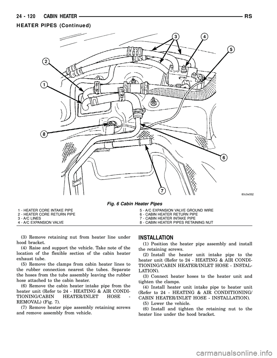
(3) Remove retaining nut from heater line under
hood bracket.
(4) Raise and support the vehicle. Take note of the
location of the flexible section of the cabin heater
exhaust tube.
(5) Remove the clamps from cabin heater lines to
the rubber connection nearest the tubes. Separate
the hoses from the tube assembly leaving the rubber
hose attached to the cabin heater.
(6) Remove the cabin heater intake pipe from the
heater unit (Refer to 24 - HEATING & AIR CONDI-
TIONING/CABIN HEATER/INLET HOSE -
REMOVAL) (Fig. 7).
(7) Remove heater pipe assembly retaining screws
and remove assembly from vehicle.INSTALLATION
(1) Position the heater pipe assembly and install
the retaining screws.
(2) Install the heater unit intake pipe to the
heater unit (Refer to 24 - HEATING & AIR CONDI-
TIONING/CABIN HEATER/INLET HOSE - INSTAL-
LATION).
(3) Connect heater hoses to the heater unit and
tighten the clamps.
(4) Install heater unit intake pipe to heater unit
(Refer to 24 - HEATING & AIR CONDITIONING/
CABIN HEATER/INLET HOSE - INSTALLATION).
(5) Lower the vehicle.
(6) Install and tighten the retaining nut to the
heater line under the hood bracket.
Fig. 6 Cabin Heater Pipes
1 - HEATER CORE INTAKE PIPE
2 - HEATER CORE RETURN PIPE
3 - A/C LINES
4 - A/C EXPANSION VALVE5 - A/C EXPANSION VALVE GROUND WIRE
6 - CABIN HEATER RETURN PIPE
7 - CABIN HEATER INTAKE PIPE
8 - CABIN HEATER PIPES RETAINING NUT
24 - 120 CABIN HEATERRS
HEATER PIPES (Continued)