radio CHRYSLER CARAVAN 2005 Workshop Manual
[x] Cancel search | Manufacturer: CHRYSLER, Model Year: 2005, Model line: CARAVAN, Model: CHRYSLER CARAVAN 2005Pages: 2339, PDF Size: 59.69 MB
Page 541 of 2339
(PCM) based upon the results. The ªVALID/INVALID
KEYº message communication is performed using a
rolling code algorithm via the Programmable Com-
munication Interface (PCI) data bus. A ªVALID KEYº
message must be sent to the Powertrain Control
Module (PCM) within two seconds of ignition ON to
free the engine from immobilization.
The SKREEM contains a Radio Frequency (RF)
transceiver and a microprocessor. The SKREEM
retains in memory the ID numbers of any Sentry Key
that is programmed to it. The maximum number of
keys that may be programmed to each module is
eight (8). The SKREEM also communicates over the
Programmable Communication Interface (PCI) data
bus with the Powertrain Control Module (PCM), the
Body Control Module (BCM), the Mechanical Instru-
ment Cluster (MIC), and the DRB IIItscan tool. The
SKREEM transmits and receives RF signals through
a tuned antenna enclosed within a molded plastic
ring formation that is integral to the SKREEM hous-
ing. When the SKREEM is properly installed on the
steering column, the antenna ring fits snugly around
the circumference of the ignition lock cylinder hous-
ing. If this ring is not mounted properly, communica-
tion problems may arise in the form of transponder-
related faults.
For added system security, each SKREEM is pro-
grammed with a unique9Secret Key9code. This code
is stored in memory and is sent over the PCI bus to
the PCM and to each key that is programmed to
work with the vehicle. The9Secret Key9code is there-
fore a common element found in all components of
the Sentry Key Immobilizer System (SKIS). In the
event that a SKREEM replacement is required, the
9Secret Key9code can be restored from the PCM by
following the SKIM replacement procedure found in
the DRB IIItscan tool. Proper completion of this
task will allow the existing ignition keys to be repro-
grammed. Therefore, new keys will NOT be needed.
In the event that the original9Secret Key9code can
not be recovered, new ignition keys will be required.
The DRB IIItscan tool will alert the technician if
key replacement is necessary. Another security code,
called a PIN, is used to gain secured access to the
SKREEM for service. The SKREEM also stores in its
memory the Vehicle Identification Number (VIN),
which it learns through a bus message from the
assembly plant tester. The SKIS scrambles the infor-
mation that is communicated between its components
in order to reduce the possibility of unauthorized
SKREEM access and/or disabling.
REMOTE KEYLESS ENTRY (RKE)
The RKE transmitter uses radio frequency signals
to communicate with the SKREEM. The SKREEM is
on the PCI bus. When the operator presses a buttonon the transmitter, it sends a specific request to the
SKREEM. In turn the SKREEM sends the appropri-
ate request over the PCI Bus to the:
²Body Control Module (BCM) to control the door
lock and unlock functions, the liftgate lock and
unlock functions, the arming and disarming of the
Vehicle Theft Security System (VTSS) (if equipped),
and the activation of illuminated entry.
²Integrated Power Module (IPM) to activate the
park lamps, the headlamps, and the horn for horn
chirp. If requested, the BCM sends a request over
the PCI Bus to the:
TIRE PRESSURE MONITORING (TPM)
If equipped with the Tire Pressure Monitoring
(TPM) System, each of the vehicles four wheels will
have a valve stem with a pressure sensor and radio
transmitter built in. Signals from the tire pressure
sensor/transmitter are received and interpreted by
the SKREEM.
A sensor/transmitter in a mounted wheel will
broadcast its detected pressure once per minute
when the vehicle is moving faster than 15 mph (24
km/h). Each sensor/transmitter's broadcast is
uniquely coded so that the SKREEM can determine
the location.
OPERATION
SENTRY KEY IMMOBILIZER
The Sentry Key Remote Entry Module (SKREEM)
receives an encrypted Radio Frequency (RF) signal
from the transponder key. The SKREEM then
decrypts the signal and broadcasts the requested
remote commands to the appropriate modules in the
vehicle over the Programmable Communication
Interface (PCI) data bus. A valid transponder key ID
must be incorporated into the RF signal in order for
the SKREEM to pass the message on to the appro-
priate modules.
Automatic transponder key synchronization is done
by the SKREEM if a valid transponder key is
inserted into the ignition cylinder, and the ignition is
turned ON. This provides a maximum operation win-
dow for RKE functions.
Each Sentry Key Remote Entry System (SKREES)
consists of a SKREEM and a transponder key. Each
system has a secret key code unique to that system.
The secret key is electronically coded in the
SKREEM and in all programmed transponder keys.
It is used for immobilization and RKE functions for
data security. In addition, each transponder key will
have a unique identification. For North America, the
options are a 3-button or 6 button integrated keys.
For Export, the options are 2-button or 5 button key
fobs. (Export does not get the integrated key).
8Q - 4 VEHICLE THEFT SECURITYRS
SENTRY KEY REMOTE ENTRY MODULE (Continued)
Page 542 of 2339
When the ignition switch is moved to the RUN
position, the SKREEM transmits an Radio Frequency
(RF) signal to the transponder in the ignition key.
The SKREEM then waits for a response RF signal
from the transponder in the key. If the response
received identifies the key as valid, the SKREEM
sends a9valid key9message to the Powertrain Con-
trol Module (PCM) over the Programmable Commu-
nication Interface (PCI) data bus. If the response
received identifies the key as invalid or no response
is received from the transponder in the ignition key,
the SKREEM sends an9invalid key9message to the
PCM. The PCM will enable or disable engine opera-
tion based upon the status of the SKREEM mes-
sages. It is important to note that the default
condition in the PCM is9invalid key.9Therefore, if no
response is received by the PCM, the engine will be
immobilized after two (2) seconds of running.
The SKREEM also sends indicator light status
messages to the Mechanical Instrument Cluster
(MIC) to operate the light. This is the method used to
turn the light ON solid or to flash it after the indi-
cator light test is complete to signify a fault in the
SKREES. If the light comes ON and stays ON solid
after the indicator light test, this signifies that the
SKREEM has detected a system malfunction and/or
that the SKREES has become inoperative. If the
SKREEM detects an invalid keyORa key-related
fault exists, the indicator light will flash following
the indicator light test. The SKREEM may also
request an audible chime if the customer key pro-
gramming feature is available and the procedure is
being utilized (Refer to 8 - ELECTRICAL/VEHICLE
THEFT SECURITY/TRANSPONDER KEY - STAN-
DARD PROCEDURE).
REMOTE KEYLESS ENTRY (RKE)
After pressing the lock button on the RKE trans-
mitter, all of the door locks will lock, the illuminated
entry will turn off (providing all doors are closed),
and the VTSS (if equipped) will arm. After pressing
the unlock button, on the RKE transmitter, one time,
the driver door lock will unlock, the illuminated
entry will turn on the courtesy lamps, and the VTSS
(if equipped) will disarm. After pressing the unlock
button a second time, the remaining door locks will
unlock. The Electronic Vehicle Information Center
(EVIC) or the DRBIIItscan tool can reprogram this
feature to unlock all of the door locks with one press
of the unlock button. If the vehicle is equipped with
the memory system, the memory message will iden-
tify which transmitter (1 or 2) sent the signal.The SKREEM is capable of retaining up to 8 indi-
vidual access codes (8 transmitters). If the PRNDL is
in any position except park, the SKREEM will dis-
able the RKE. The 4 button transmitter uses
1-CR2032 battery. The minimum battery life is
approximately 4.7 years based on 20 transmissions a
day at 84ÉF (25ÉC). Use the DRBIIItscan tool or the
Miller Tool 9001 RF Detector to test the RKE trans-
mitter. Use the DRBIIItor the customer program-
ming method to program the RKE system. However,
the SKREEM will only allow RKE programming
when the ignition is in the ON position, the PRNDL
is in park position, and the VTSS (if equipped) is dis-
armed.
TIRE PRESSURE MONITORING (TPM)
The SKREEM monitors the signals from the tire
pressure sensor/transmitters and determines if any
tire has gone below the low pressure threshold LOW
TIRE PRESSURE THRESHOLDS table.
LOW TIRE PRESSURE THRESHOLDS
SYSTEM STATUS
INDICATORTIRE PRESSURE
ON 193 kPa (28 PSI)
OFF 227 kPa (33 PSI)
CRITICAL AND NON-CRITICAL SYSTEM ALERTS
CRITICAL:A critical alert will be triggered when
a tire pressure has gone below a set threshold pres-
sure. The EVIC display will display ªX TIRE(S) LOW
PRESSUREº. ªXº will be the number of tires report-
ing low pressure. The message will display for the
duration of the current ignition cycle or until an
EVIC button is pressed. If the display is removed
without correcting the condition, it will reappear 300
seconds to warn the driver of the low pressure condi-
tion.
NON-CRITICAL:A non-critical alert will be trig-
gered when no signal is received from a sensor/trans-
mitter. The EVIC display in the cluster will display
ªSERVICE TIRE SYSTEM SOON.º
DIAGNOSIS AND TESTING - SENTRY KEY
REMOTE ENTRY MODULE
For proper diagnosis and testing of the Sentry Key
Remote Entry Module (SKREEM), use a DRBllltand
refer to the proper Body Diagnostic Procedures infor-
mation.
RSVEHICLE THEFT SECURITY8Q-5
SENTRY KEY REMOTE ENTRY MODULE (Continued)
Page 543 of 2339

REMOVAL
(1) Disconnect and isolate the battery negative
cable.
(2) Remove the Steering Column Opening Cover
(Refer to 23 - BODY/INSTRUMENT PANEL/STEER-
ING COLUMN OPENING COVER - REMOVAL).
(3) Remove the steering column upper and lower
shrouds (Refer to 19 - STEERING/COLUMN/UPPER
SHROUD - REMOVAL) and (Refer to 19 - STEER-
ING/COLUMN/LOWER SHROUD - REMOVAL).
(4) Disengage the steering column wire harness
from the Sentry Key Remote Entry Module
(SKREEM).
(5) Remove the one screws securing the SKREEM
to the steering column.
(6) Rotate the SKREEM upwards and then to the
side away from the steering column to slide the
SKREEM antenna ring from around the ignition
switch lock cylinder housing.
(7) Remove the SKREEM from the vehicle.
INSTALLATION
(1) Slip the Sentry Key Remote Entry Module
(SKREEM) antenna ring around the ignition switch
lock cylinder housing. Rotate the SKREEM down-
wards and then towards the steering column.
(2) Install the one screws securing the SKREEM to
the steering column.
(3) Connect the steering column wire harness to
the SKREEM.
(4) Install the steering column upper and lower
shrouds (Refer to 19 - STEERING/COLUMN/UPPER
SHROUD - INSTALLATION) and (Refer to 19 -
STEERING/COLUMN/LOWER SHROUD - INSTAL-
LATION).
(5) Install the Steering Column Opening Cover
(Refer to 23 - BODY/INSTRUMENT PANEL/STEER-
ING COLUMN OPENING COVER - INSTALLA-
TION)
(6) Connect the battery negative cable.
TRANSPONDER KEY
DESCRIPTION
The Sentry Key Remote Entry System (SKREES)
uses a transponder chip that is integral to the circuit
board of the integrated ignition key (SKREES and
RKE incorporated) to communicate with the Sentry
Key Remote Entry Module (SKREEM). Ignition keys
are supplied with the vehicle when it is shipped from
the factory.
For export vehicles equipped with SKREES, the
transponder chip is undermolded within the head of
the key.
OPERATION
Each Sentry Key has a unique transponder identi-
fication code permanently programmed into it by the
manufacturer. Likewise, the Sentry Key Remote
Entry Module (SKREEM) has a unique9Secret Key9
code programmed into it by the manufacturer as
well. When a Sentry Key is programmed into the
memory of the SKREEM, the SKREEM stores the
transponder identification code from the Sentry Key,
and the Sentry Key learns the9Secret Key9code from
the SKREEM. Once the Sentry Key learns the
9Secret Key9code of the SKREEM, it is also perma-
nently programmed into the transponder's memory.
Therefore, blank keys for the Sentry Key Remote
Entry System (SKREES) must be programmed by
the SKREEM in addition to being cut to match the
mechanical coding of the ignition lock cylinder. Refer
to Electrical, Vehicle Theft Security, Transponder
Key, Standard Procedure - Transponder Program-
ming.
The Sentry Key's transponder is within the range
of the SKREEM's transceiver antenna ring when it is
inserted into the ignition lock cylinder. When the
ignition switch is turned to the ON position, the
SKREEM communicates with the Sentry Key via a
radio frequency (RF) signal. The SKREEM deter-
mines if a valid key is present based on the informa-
tion it receives from the Sentry Key. If a valid key is
detected, that fact is communicated to the PCM via
the PCI bus and the vehicle is allowed to continue
running. If an invalid key is received by the PCM or
no status at all is communicated, the vehicle will
stall after two (2) seconds of running. The indicator
light will be flashing at this point. The Sentry Key's
transponder can not be repaired. If it is faulty or
damaged, it must be replaced.
Common communication problems:
²Two transponder keys too close together.
²Speed Pass too close to transponder key.
Solid indicator that there is a system failure.
²Loss of PCM communication.
²Failed antenna circuit.
STANDARD PROCEDURE - TRANSPONDER
PROGRAMMING
USING A DRBIIITSCAN TOOL
All Sentry Keys included with the vehicle are pre-
programmed to work with the Sentry Key Remote
Entry System (SKREES) when it is shipped from the
factory. The Sentry Key Remote Entry Module
(SKREEM) can be programmed to recognize up to a
total of eight Sentry Keys. When programming a
blank Sentry Key transponder, the key must first be
cut to match the ignition lock cylinder of the vehicle
for which it will be used. The vehicle's four digit PIN
8Q - 6 VEHICLE THEFT SECURITYRS
SENTRY KEY REMOTE ENTRY MODULE (Continued)
Page 560 of 2339
NAVIGATION/TELECOMMUNICATION
TABLE OF CONTENTS
page page
NAVIGATION/TELECOMMUNICATION
DESCRIPTION..........................1
OPERATION............................1
DIAGNOSIS AND TESTING
TELECOMMUNICATION.................1HANDS FREE MODULE
REMOVAL.............................3
INSTALLATION..........................3
NAVIGATION/
TELECOMMUNICATION
DESCRIPTION
TELECOMMUNICATIONS
A hands-free cellular system is an available option
on this vehicle. It uses BluetoothŸ technology to pro-
vide wireless communication between the operator's
compatible cellular telephone and the vehicle's
on-board receiver.
The system uses voice recognition technology to
control operation. The incoming voice is broadcast
through the vehicle's radio speakers, automatically
overriding any other audio signals on the speakers
when the hands-free system is in use. A microphone
in the rearview mirror picks up vehicle occupant's
voices. If a call is in progress when the ignition is
switched off, the hands-free system will continue to
operate for up to 45 seconds as part of the Accessory
Relay Delay function. Thereafter, the call can con-
tinue on the hand-held telephone.
The center console front storage compartment
includes a cellular telephone holder, but the system
will communicate with a telephone that is anywhere
within the vehicle. However, covering the hand held
phone or the hands-free phone module with a metal
object may block the signal. The system will recog-
nize up to seven telephones, each of which is given a
spoken identification by the user during the setup
process. The system includes Spanish voice recogni-
tion in addition to English.
Two buttons on the rearview mirror, identified with
ISO icons, control the system: A9phone9button turns
the system on and off; a9voice recognition9(or voice
command) button prompts the hands-free system to
listen for a voice command.
OPERATION
TELECOMMUNICATION
Two buttons on the rearview mirror, identified with
ISO icons, control the system: A9phone9button turns
the system on and off; a9voice recognition9(or voice
command) button prompts the hands-free system to
listen for a voice command. The system includes the
following features:
²Phonebook - Stores telephone numbers for later
recall by name or other verbal identification, called a
voice tag, and memory location.
²Four memory locations - Home, Work, Mobile
and Pager. A maximum of 32 unique names or voice
tags may be stored at the same time, with a different
number in each of the four memory locations.
²Voice tag dialing - Dials the number associated
with a voice tag and memory location.
²Digit dialing - Dials the telephone number by
recognizing the names of the digits as they are spo-
ken.
²Receiving calls - A voice prompt notifies the user
of an incoming call. Pressing the ªphoneº button
answers the call.
²Privacy Mode - Switches the call to the hand-
held telephone and the hands-free system and back
again using the ªvoice recognitionº (or ªvoice com-
mandº) button and a voice command, if desired.
DIAGNOSIS AND TESTING
TELECOMMUNICATION
Any diagnosis of the Telecommunication sys-
tem should begin with the use of the DRB IIIt
diagnostic tool. For information on the use of
the DRB IIIt, refer to the appropriate Diagnos-
tic Service Information.
For complete circuit diagrams, refer to the appro-
priate wiring information.
RSNAVIGATION/TELECOMMUNICATION8T-1
Page 583 of 2339
Component Page
Ignition Coil......................... 8W-30
Ignition Switch....................... 8W-10
Impact Sensors....................... 8W-43
Inlet Air Temperature Sensor............ 8W-30
Instrument Cluster.................... 8W-40
Instrument Panel Switch
Bank.................. 8W-43, 44, 52, 53, 63
Integrated Power Module............... 8W-10
Knock Sensor........................ 8W-30
Lamp Assemblies...................... 8W-51
License Lamp..................... 8W-51, 61
Lift Pump Motor...................... 8W-30
Lift Pump Relay...................... 8W-30
Liftgate Ajar Switch................ 8W-39, 61
Liftgate Cinch/Release Motor............ 8W-61
Liftgate Flood Lamps.................. 8W-44
Liftgate Pinch Sensors................. 8W-61
Low Beam Lamps..................... 8W-50
Manifold Absolute Pressure Sensor........ 8W-30
Mass Air Flow Sensor.................. 8W-30
Memory Seat/Mirror/Adjustable Pedals
Module...................... 8W-56, 62, 63
Memory Set Switch.................... 8W-63
Message Center.................... 8W-40, 46
Mode Door Actuator................... 8W-42
Multi-Function Switch............ 8W-50, 52, 53
Natural Vacuum Leak Detection Assembly . . 8W-30
Occupant Classification Module.......... 8W-43
Occupant Restraint Controller........... 8W-43
Overhead Console..................... 8W-49
Oxygen Sensors....................... 8W-30
Park Assist Display.................... 8W-56
Park Assist Module.................... 8W-56
Park Assist Sensors.................... 8W-56
Park Lamp Relay..................... 8W-10
Park Lamps.......................... 8W-50
Park/Turn Signal Lamps................ 8W-50
Parking Brake Switch.................. 8W-40
Power Folding Mirror Switch............ 8W-62
Power Liftgate Module................. 8W-61
Power Liftgate Motor.................. 8W-61
Power Mirror Switch................... 8W-62
Power Mirrors........................ 8W-62
Power Outlets........................ 8W-41
Power Seat Circuit Breaker.............. 8W-10
Power Seat Motors.................... 8W-63
Power Seat Position Sensors............. 8W-63
Power Seat Switches................... 8W-63
Power Window Circuit Breaker........... 8W-10
Power Window Motors.................. 8W-60
Power Window Switches................ 8W-60
Powertrain Control Module........... 8W-30, 31
PTCs............................... 8W-10
Radiator Fan Relaies................... 8W-42Component Page
Radiator Fans........................ 8W-42
Radio............................... 8W-47
Reading Lamps....................... 8W-44
Rear A/C-Heater Unit.................. 8W-42
Rear Auto Temp Control Switch.......... 8W-42
Rear Blower Control Switches............ 8W-42
Rear Blower Motor Power Module......... 8W-42
Rear Dome Lamp..................... 8W-44
Rear Intrusion Sensor.................. 8W-39
Rear Mode Motor..................... 8W-42
Rear Temperature Motor................ 8W-42
Rear View Mirror................ 8W-49, 55, 62
Rear Window Defogger Grid............. 8W-48
Rear Wiper Motor..................... 8W-53
Recirculation Door Actuator............. 8W-42
Remote Radio Switches................. 8W-47
Repeater Lamps...................... 8W-52
Seat Belt Switches.................... 8W-43
Seat Belt Tensioners................... 8W-43
Seat Weight Sensor.................... 8W-43
Sentry Key Remote Entry Module......... 8W-39
Siren............................... 8W-39
Sliding Door Control Modules............ 8W-61
Sliding Door Latch Sensing Switches...... 8W-61
Sliding Door Lock Motors............... 8W-61
Sliding Door Motors................... 8W-61
Speakers............................ 8W-47
Speed Control Servo................... 8W-33
Speed Control Switches................. 8W-33
Speed Sensors........................ 8W-31
Splices.............................. 8W-70
Starter Motor........................ 8W-21
Starter Motor Relay................... 8W-21
Sunroof Module....................... 8W-64
Sunroof Switch....................... 8W-64
Thatcham Alarm Indicator.............. 8W-39
Thatcham Alarm Module................ 8W-39
Throttle Position Sensor................ 8W-30
Traction Control Switch................. 8W-35
Trailer Tow Connector.................. 8W-54
Transmission Control Module............ 8W-31
Transmission Control Relay............. 8W-31
Transmission Range Sensor.............. 8W-31
Transmission Solenoid/Pressure Switch
Assembly.......................... 8W-31
Turn Signal Lamps.................... 8W-52
Vehicle Speed Sensor................... 8W-30
Vent Motors.......................... 8W-60
Visor/Vanity Lamps.................... 8W-44
Washer Fluid Level Switch.............. 8W-53
Washer Pump Motor................... 8W-53
Water In Fuel Sensor.................. 8W-30
Wheel Speed Sensors................... 8W-35
Wiper Module........................ 8W-53
8W - 02 - 2 8W-02 COMPONENT INDEXRS
Page 585 of 2339
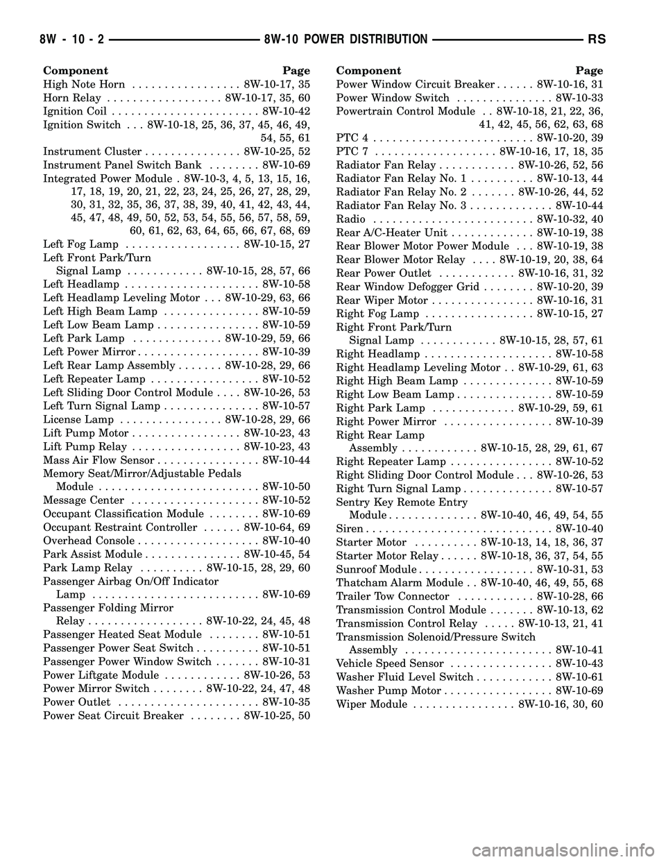
Component Page
High Note Horn................. 8W-10-17, 35
Horn Relay.................. 8W-10-17, 35, 60
Ignition Coil....................... 8W-10-42
Ignition Switch . . . 8W-10-18, 25, 36, 37, 45, 46, 49,
54, 55, 61
Instrument Cluster............... 8W-10-25, 52
Instrument Panel Switch Bank........ 8W-10-69
Integrated Power Module . 8W-10-3, 4, 5, 13, 15, 16,
17, 18, 19, 20, 21, 22, 23, 24, 25, 26, 27, 28, 29,
30, 31, 32, 35, 36, 37, 38, 39, 40, 41, 42, 43, 44,
45, 47, 48, 49, 50, 52, 53, 54, 55, 56, 57, 58, 59,
60, 61, 62, 63, 64, 65, 66, 67, 68, 69
Left Fog Lamp.................. 8W-10-15, 27
Left Front Park/Turn
Signal Lamp............ 8W-10-15, 28, 57, 66
Left Headlamp..................... 8W-10-58
Left Headlamp Leveling Motor . . . 8W-10-29, 63, 66
Left High Beam Lamp............... 8W-10-59
Left Low Beam Lamp................ 8W-10-59
Left Park Lamp.............. 8W-10-29, 59, 66
Left Power Mirror................... 8W-10-39
Left Rear Lamp Assembly....... 8W-10-28, 29, 66
Left Repeater Lamp................. 8W-10-52
Left Sliding Door Control Module.... 8W-10-26, 53
Left Turn Signal Lamp............... 8W-10-57
License Lamp................ 8W-10-28, 29, 66
Lift Pump Motor................. 8W-10-23, 43
Lift Pump Relay................. 8W-10-23, 43
Mass Air Flow Sensor................ 8W-10-44
Memory Seat/Mirror/Adjustable Pedals
Module......................... 8W-10-50
Message Center.................... 8W-10-52
Occupant Classification Module........ 8W-10-69
Occupant Restraint Controller...... 8W-10-64, 69
Overhead Console................... 8W-10-40
Park Assist Module............... 8W-10-45, 54
Park Lamp Relay.......... 8W-10-15, 28, 29, 60
Passenger Airbag On/Off Indicator
Lamp.......................... 8W-10-69
Passenger Folding Mirror
Relay.................. 8W-10-22, 24, 45, 48
Passenger Heated Seat Module........ 8W-10-51
Passenger Power Seat Switch.......... 8W-10-51
Passenger Power Window Switch....... 8W-10-31
Power Liftgate Module............ 8W-10-26, 53
Power Mirror Switch........ 8W-10-22, 24, 47, 48
Power Outlet...................... 8W-10-35
Power Seat Circuit Breaker........ 8W-10-25, 50Component Page
Power Window Circuit Breaker...... 8W-10-16, 31
Power Window Switch............... 8W-10-33
Powertrain Control Module . . 8W-10-18, 21, 22, 36,
41, 42, 45, 56, 62, 63, 68
PTC4 ......................... 8W-10-20, 39
PTC7 ................... 8W-10-16, 17, 18, 35
Radiator Fan Relay............ 8W-10-26, 52, 56
Radiator Fan Relay No. 1.......... 8W-10-13, 44
Radiator Fan Relay No. 2....... 8W-10-26, 44, 52
Radiator Fan Relay No. 3............. 8W-10-44
Radio......................... 8W-10-32, 40
Rear A/C-Heater Unit............. 8W-10-19, 38
Rear Blower Motor Power Module . . . 8W-10-19, 38
Rear Blower Motor Relay.... 8W-10-19, 20, 38, 64
Rear Power Outlet............ 8W-10-16, 31, 32
Rear Window Defogger Grid........ 8W-10-20, 39
Rear Wiper Motor................ 8W-10-16, 31
Right Fog Lamp................. 8W-10-15, 27
Right Front Park/Turn
Signal Lamp............ 8W-10-15, 28, 57, 61
Right Headlamp.................... 8W-10-58
Right Headlamp Leveling Motor . . 8W-10-29, 61, 63
Right High Beam Lamp.............. 8W-10-59
Right Low Beam Lamp............... 8W-10-59
Right Park Lamp............. 8W-10-29, 59, 61
Right Power Mirror................. 8W-10-39
Right Rear Lamp
Assembly............ 8W-10-15, 28, 29, 61, 67
Right Repeater Lamp................ 8W-10-52
Right Sliding Door Control Module . . . 8W-10-26, 53
Right Turn Signal Lamp.............. 8W-10-57
Sentry Key Remote Entry
Module.............. 8W-10-40, 46, 49, 54, 55
Siren............................. 8W-10-40
Starter Motor.......... 8W-10-13, 14, 18, 36, 37
Starter Motor Relay...... 8W-10-18, 36, 37, 54, 55
Sunroof Module.................. 8W-10-31, 53
Thatcham Alarm Module . . 8W-10-40, 46, 49, 55, 68
Trailer Tow Connector............ 8W-10-28, 66
Transmission Control Module....... 8W-10-13, 62
Transmission Control Relay..... 8W-10-13, 21, 41
Transmission Solenoid/Pressure Switch
Assembly....................... 8W-10-41
Vehicle Speed Sensor................ 8W-10-43
Washer Fluid Level Switch............ 8W-10-61
Washer Pump Motor................. 8W-10-69
Wiper Module................ 8W-10-16, 30, 60
8W - 10 - 2 8W-10 POWER DISTRIBUTIONRS
Page 654 of 2339
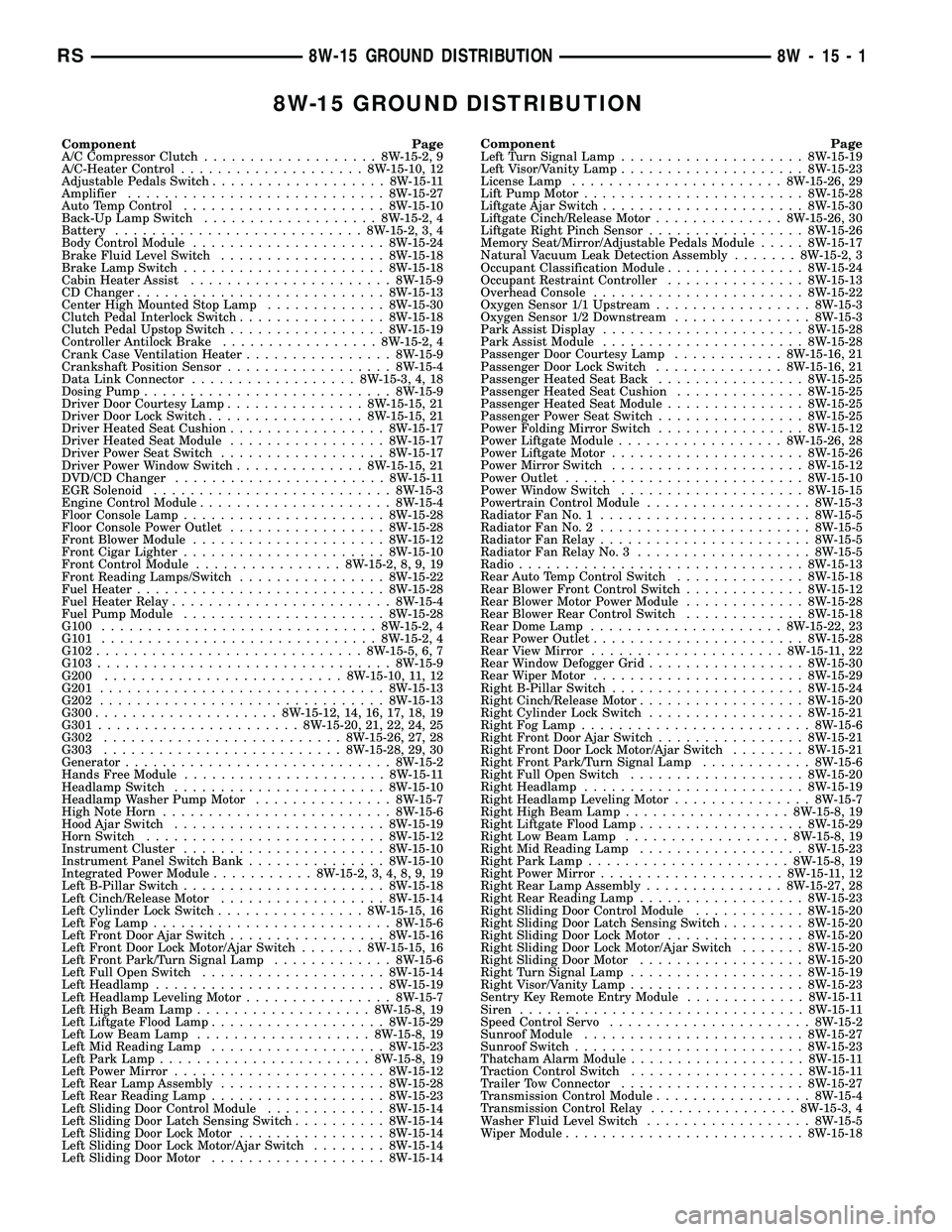
8W-15 GROUND DISTRIBUTION
Component Page
A/C Compressor Clutch...................8W-15-2, 9
A/C-Heater Control....................8W-15-10, 12
Adjustable Pedals Switch...................8W-15-11
Amplifier............................8W-15-27
Auto Temp Control......................8W-15-10
Back-Up Lamp Switch...................8W-15-2, 4
Battery...........................8W-15-2, 3, 4
Body Control Module.....................8W-15-24
Brake Fluid Level Switch..................8W-15-18
Brake Lamp Switch......................8W-15-18
Cabin Heater Assist......................8W-15-9
CD Changer...........................8W-15-13
Center High Mounted Stop Lamp.............8W-15-30
Clutch Pedal Interlock Switch................8W-15-18
Clutch Pedal Upstop Switch.................8W-15-19
Controller Antilock Brake.................8W-15-2, 4
Crank Case Ventilation Heater................8W-15-9
Crankshaft Position Sensor..................8W-15-4
Data Link Connector..................8W-15-3, 4, 18
Dosing Pump...........................8W-15-9
Driver Door Courtesy Lamp...............8W-15-15, 21
Driver Door Lock Switch.................8W-15-15, 21
Driver Heated Seat Cushion.................8W-15-17
Driver Heated Seat Module.................8W-15-17
Driver Power Seat Switch..................8W-15-17
Driver Power Window Switch..............8W-15-15, 21
DVD/CD Changer.......................8W-15-11
EGR Solenoid..........................8W-15-3
Engine Control Module.....................8W-15-4
Floor Console Lamp......................8W-15-28
Floor Console Power Outlet.................8W-15-28
Front Blower Module.....................8W-15-12
Front Cigar Lighter......................8W-15-10
Front Control Module................8W-15-2, 8, 9, 19
Front Reading Lamps/Switch................8W-15-22
Fuel Heater...........................8W-15-28
Fuel Heater Relay........................8W-15-4
Fuel Pump Module......................8W-15-28
G100..............................8W-15-2, 4
G101..............................8W-15-2, 4
G102.............................8W-15-5, 6, 7
G103................................8W-15-9
G200..........................8W-15-10, 11, 12
G201...............................8W-15-13
G202...............................8W-15-13
G300....................8W-15-12, 14, 16, 17, 18, 19
G301......................8W-15-20, 21, 22, 24, 25
G302..........................8W-15-26, 27, 28
G303..........................8W-15-28, 29, 30
Generator.............................8W-15-2
Hands Free Module......................8W-15-11
Headlamp Switch.......................8W-15-10
Headlamp Washer Pump Motor...............8W-15-7
High Note Horn.........................8W-15-6
Hood Ajar Switch.......................8W-15-19
Horn Switch..........................8W-15-12
Instrument Cluster......................8W-15-10
Instrument Panel Switch Bank...............8W-15-10
Integrated Power Module...........8W-15-2, 3, 4, 8, 9, 19
Left B-Pillar Switch......................8W-15-18
Left Cinch/Release Motor..................8W-15-14
Left Cylinder Lock Switch................8W-15-15, 16
Left Fog Lamp..........................8W-15-6
Left Front Door Ajar Switch.................8W-15-16
Left Front Door Lock Motor/Ajar Switch.......8W-15-15, 16
Left Front Park/Turn Signal Lamp.............8W-15-6
Left Full Open Switch....................8W-15-14
Left Headlamp.........................8W-15-19
Left Headlamp Leveling Motor................8W-15-7
Left High Beam Lamp...................8W-15-8, 19
Left Liftgate Flood Lamp...................8W-15-29
Left Low Beam Lamp...................8W-15-8, 19
Left Mid Reading Lamp...................8W-15-23
Left Park Lamp.......................8W-15-8, 19
Left Power Mirror.......................8W-15-12
Left Rear Lamp Assembly..................8W-15-28
Left Rear Reading Lamp...................8W-15-23
Left Sliding Door Control Module.............8W-15-14
Left Sliding Door Latch Sensing Switch..........8W-15-14
Left Sliding Door Lock Motor................8W-15-14
Left Sliding Door Lock Motor/Ajar Switch........8W-15-14
Left Sliding Door Motor...................8W-15-14Component Page
Left Turn Signal Lamp....................8W-15-19
Left Visor/Vanity Lamp....................8W-15-23
License Lamp.......................8W-15-26, 29
Lift Pump Motor........................8W-15-28
Liftgate Ajar Switch......................8W-15-30
Liftgate Cinch/Release Motor..............8W-15-26, 30
Liftgate Right Pinch Sensor.................8W-15-26
Memory Seat/Mirror/Adjustable Pedals Module.....8W-15-17
Natural Vacuum Leak Detection Assembly.......8W-15-2, 3
Occupant Classification Module...............8W-15-24
Occupant Restraint Controller...............8W-15-13
Overhead Console.......................8W-15-22
Oxygen Sensor 1/1 Upstream.................8W-15-3
Oxygen Sensor 1/2 Downstream...............8W-15-3
Park Assist Display......................8W-15-28
Park Assist Module......................8W-15-28
Passenger Door Courtesy Lamp............8W-15-16, 21
Passenger Door Lock Switch..............8W-15-16, 21
Passenger Heated Seat Back................8W-15-25
Passenger Heated Seat Cushion..............8W-15-25
Passenger Heated Seat Module...............8W-15-25
Passenger Power Seat Switch................8W-15-25
Power Folding Mirror Switch................8W-15-12
Power Liftgate Module..................8W-15-26, 28
Power Liftgate Motor.....................8W-15-26
Power Mirror Switch.....................8W-15-12
Power Outlet..........................8W-15-10
Power Window Switch....................8W-15-15
Powertrain Control Module..................8W-15-3
Radiator Fan No. 1.......................8W-15-5
Radiator Fan No. 2.......................8W-15-5
Radiator Fan Relay.......................8W-15-5
Radiator Fan Relay No. 3...................8W-15-5
Radio...............................8W-15-13
Rear Auto Temp Control Switch..............8W-15-18
Rear Blower Front Control Switch.............8W-15-12
Rear Blower Motor Power Module.............8W-15-28
Rear Blower Rear Control Switch.............8W-15-18
Rear Dome Lamp.....................8W-15-22, 23
Rear Power Outlet.......................8W-15-28
Rear View Mirror.....................8W-15-11, 22
Rear Window Defogger Grid.................8W-15-30
Rear Wiper Motor.......................8W-15-29
Right B-Pillar Switch.....................8W-15-24
Right Cinch/Release Motor..................8W-15-20
Right Cylinder Lock Switch.................8W-15-21
Right Fog Lamp.........................8W-15-6
Right Front Door Ajar Switch................8W-15-21
Right Front Door Lock Motor/Ajar Switch........8W-15-21
Right Front Park/Turn Signal Lamp............8W-15-6
Right Full Open Switch...................8W-15-20
Right Headlamp........................8W-15-19
Right Headlamp Leveling Motor...............8W-15-7
Right High Beam Lamp..................8W-15-8, 19
Right Liftgate Flood Lamp..................8W-15-29
Right Low Beam Lamp..................8W-15-8, 19
Right Mid Reading Lamp..................8W-15-23
Right Park Lamp......................8W-15-8, 19
Right Power Mirror....................8W-15-11, 12
Right Rear Lamp Assembly...............8W-15-27, 28
Right Rear Reading Lamp..................8W-15-23
Right Sliding Door Control Module............8W-15-20
Right Sliding Door Latch Sensing Switch.........8W-15-20
Right Sliding Door Lock Motor...............8W-15-20
Right Sliding Door Lock Motor/Ajar Switch.......8W-15-20
Right Sliding Door Motor..................8W-15-20
Right Turn Signal Lamp...................8W-15-19
Right Visor/Vanity Lamp...................8W-15-23
Sentry Key Remote Entry Module.............8W-15-11
Siren...............................8W-15-11
Speed Control Servo......................8W-15-2
Sunroof Module........................8W-15-27
Sunroof Switch.........................8W-15-23
Thatcham Alarm Module...................8W-15-11
Traction Control Switch...................8W-15-11
Trailer Tow Connector....................8W-15-27
Transmission Control Module.................8W-15-4
Transmission Control Relay................8W-15-3, 4
Washer Fluid Level Switch..................8W-15-5
Wiper Module..........................8W-15-18
RS8W-15 GROUND DISTRIBUTION8W-15-1
Page 684 of 2339
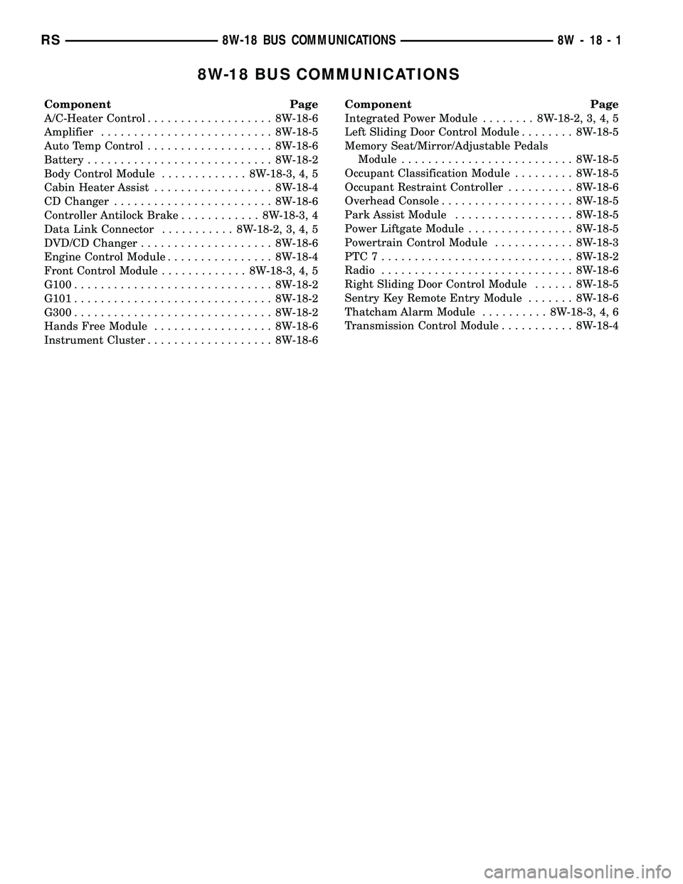
8W-18 BUS COMMUNICATIONS
Component Page
A/C-Heater Control................... 8W-18-6
Amplifier.......................... 8W-18-5
Auto Temp Control................... 8W-18-6
Battery............................ 8W-18-2
Body Control Module............. 8W-18-3, 4, 5
Cabin Heater Assist.................. 8W-18-4
CD Changer........................ 8W-18-6
Controller Antilock Brake............ 8W-18-3, 4
Data Link Connector........... 8W-18-2, 3, 4, 5
DVD/CD Changer.................... 8W-18-6
Engine Control Module................ 8W-18-4
Front Control Module............. 8W-18-3, 4, 5
G100.............................. 8W-18-2
G101.............................. 8W-18-2
G300.............................. 8W-18-2
Hands Free Module.................. 8W-18-6
Instrument Cluster................... 8W-18-6Component Page
Integrated Power Module........ 8W-18-2, 3, 4, 5
Left Sliding Door Control Module........ 8W-18-5
Memory Seat/Mirror/Adjustable Pedals
Module.......................... 8W-18-5
Occupant Classification Module......... 8W-18-5
Occupant Restraint Controller.......... 8W-18-6
Overhead Console.................... 8W-18-5
Park Assist Module.................. 8W-18-5
Power Liftgate Module................ 8W-18-5
Powertrain Control Module............ 8W-18-3
PTC7............................. 8W-18-2
Radio............................. 8W-18-6
Right Sliding Door Control Module...... 8W-18-5
Sentry Key Remote Entry Module....... 8W-18-6
Thatcham Alarm Module.......... 8W-18-3, 4, 6
Transmission Control Module........... 8W-18-4
RS8W-18 BUS COMMUNICATIONS8W-18-1
Page 774 of 2339

8W-41 HORN/CIGAR LIGHTER/POWER OUTLET
Component Page
Accessory Relay................... 8W-41-3, 4
Clockspring........................ 8W-41-2
Data Link Connector................. 8W-41-4
Floor Console Lamp.................. 8W-41-4
Floor Console Power Outlet............ 8W-41-4
Front Cigar Lighter.................. 8W-41-3
Front Control Module............. 8W-41-2, 3, 4
Fuse 5............................ 8W-41-3
Fuse 6.......................... 8W-41-3, 4
Fuse 8............................ 8W-41-2
G102.............................. 8W-41-2Component Page
G200.......................... 8W-41-2, 3, 4
G302............................ 8W-41-3, 4
High Note Horn..................... 8W-41-2
Horn Relay......................... 8W-41-2
Horn Switch........................ 8W-41-2
Integrated Power Module.......... 8W-41-2, 3, 4
Power Outlet....................... 8W-41-4
PTC7............................. 8W-41-4
Radio............................. 8W-41-3
Rear Power Outlet................... 8W-41-3
RS8W-41 HORN/CIGAR LIGHTER/POWER OUTLET8W-41-1
Page 806 of 2339

8W-44 INTERIOR LIGHTING
Component Page
A/C-Heater Control................... 8W-44-8
Accessory Relay..................... 8W-44-4
Auto Temp Control................... 8W-44-8
Body Control Module . . . 8W-44-2, 3, 4, 5, 7, 8, 9, 10
Driver Door Courtesy Lamp............ 8W-44-2
Floor Console Lamp................ 8W-44-4, 5
Floor Console Power Outlet............ 8W-44-4
Front Control Module................. 8W-44-4
Front Reading Lamps/Switch....... 8W-44-2, 4, 5
Fuse 6............................ 8W-44-4
G200............................ 8W-44-7, 8
G300............................ 8W-44-2, 8
G301........................ 8W-44-2, 3, 5, 6
G302.............................. 8W-44-4
G303........................... 8W-44-9, 10
Headlamp Switch.................... 8W-44-3
Instrument Cluster................... 8W-44-7Component Page
Instrument Panel Switch Bank......... 8W-44-7
Integrated Power Module.............. 8W-44-4
Left Liftgate Flood Lamp........... 8W-44-9, 10
Left Mid Reading Lamp............... 8W-44-3
Left Rear Reading Lamp.............. 8W-44-3
Left Visor/Vanity Lamp............. 8W-44-5, 6
Overhead Console.................... 8W-44-5
Passenger Door Courtesy Lamp......... 8W-44-2
Radio............................. 8W-44-7
Rear Auto Temp Control Switch......... 8W-44-8
Rear Blower Rear Control Switch........ 8W-44-8
Rear Dome Lamp.................. 8W-44-3, 5
Rear Power Outlet................... 8W-44-4
Right Liftgate Flood Lamp.......... 8W-44-9, 10
Right Mid Reading Lamp.............. 8W-44-3
Right Rear Reading Lamp........... 8W-44-3, 4
Right Visor/Vanity Lamp............ 8W-44-5, 6
RS8W-44 INTERIOR LIGHTING8W-44-1