wheel torque CHRYSLER CARAVAN 2005 Workshop Manual
[x] Cancel search | Manufacturer: CHRYSLER, Model Year: 2005, Model line: CARAVAN, Model: CHRYSLER CARAVAN 2005Pages: 2339, PDF Size: 59.69 MB
Page 338 of 2339
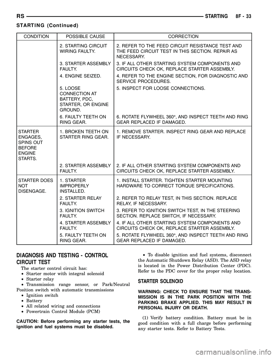
CONDITION POSSIBLE CAUSE CORRECTION
2. STARTING CIRCUIT
WIRING FAULTY.2. REFER TO THE FEED CIRCUIT RESISTANCE TEST AND
THE FEED CIRCUIT TEST IN THIS SECTION. REPAIR AS
NECESSARY.
3. STARTER ASSEMBLY
FAULTY.3. IF ALL OTHER STARTING SYSTEM COMPONENTS AND
CIRCUITS CHECK OK, REPLACE STARTER ASSEMBLY.
4. ENGINE SEIZED. 4. REFER TO THE ENGINE SECTION, FOR DIAGNOSTIC AND
SERVICE PROCEDURES.
5. LOOSE
CONNECTION AT
BATTERY, PDC,
STARTER, OR ENGINE
GROUND.5. INSPECT FOR LOOSE CONNECTIONS.
6. FAULTY TEETH ON
RING GEAR.6. ROTATE FLYWHEEL 360É, AND INSPECT TEETH AND RING
GEAR REPLACED IF DAMAGED.
STARTER
ENGAGES,
SPINS OUT
BEFORE
ENGINE
STARTS.1. BROKEN TEETH ON
STARTER RING GEAR.1. REMOVE STARTER. INSPECT RING GEAR AND REPLACE
IF NECESSARY.
2. STARTER ASSEMBLY
FAULTY.2. IF ALL OTHER STARTING SYSTEM COMPONENTS AND
CIRCUITS CHECK OK, REPLACE STARTER ASSEMBLY.
STARTER DOES
NOT
DISENGAGE.1. STARTER
IMPROPERLY
INSTALLED.1. INSTALL STARTER. TIGHTEN STARTER MOUNTING
HARDWARE TO CORRECT TORQUE SPECIFICATIONS.
2. STARTER RELAY
FAULTY.2. REFER TO RELAY TEST, IN THIS SECTION. REPLACE
RELAY, IF NECESSARY.
3. IGNITION SWITCH
FAULTY.3. REFER TO IGNITION SWITCH TEST, IN THE STEERING
SECTION. REPLACE SWITCH, IF NECESSARY.
4. STARTER ASSEMBLY
FAULTY.4. IF ALL OTHER STARTING SYSTEM COMPONENTS AND
CIRCUITS CHECK OK, REPLACE STARTER ASSEMBLY.
5. FAULTY TEETH ON
RING GEAR.5. ROTATE FLYWHEEL 360É, AND INSPECT TEETH AND RING
GEAR REPLACED IF DAMAGED.
DIAGNOSIS AND TESTING - CONTROL
CIRCUIT TEST
The starter control circuit has:
²Starter motor with integral solenoid
²Starter relay
²Transmission range sensor, or Park/Neutral
Position switch with automatic transmissions
²Ignition switch
²Battery
²All related wiring and connections
²Powertrain Control Module (PCM)
CAUTION: Before performing any starter tests, the
ignition and fuel systems must be disabled.²To disable ignition and fuel systems, disconnect
the Automatic Shutdown Relay (ASD). The ASD relay
is located in the Power Distribution Center (PDC).
Refer to the PDC cover for the proper relay location.
STARTER SOLENOID
WARNING: CHECK TO ENSURE THAT THE TRANS-
MISSION IS IN THE PARK POSITION WITH THE
PARKING BRAKE APPLIED. THIS MAY RESULT IN
PERSONAL INJURY OR DEATH.
(1) Verify battery condition. Battery must be in
good condition with a full charge before performing
any starter tests. Refer to Battery Tests.
RSSTARTING8F-33
STARTING (Continued)
Page 371 of 2339
INSTALLATION - 3.3/3.8L
(1) Install coil over studs on bracket.
(2) Install 2 nuts to the ignition coil studs. Tighten
nuts and bolts.
(3) Connect the electrical connector to the ignition
coil.
(4) Install the ignition cables to the ignition coil.
(5) Reposition the Power steering reservoir. Slide
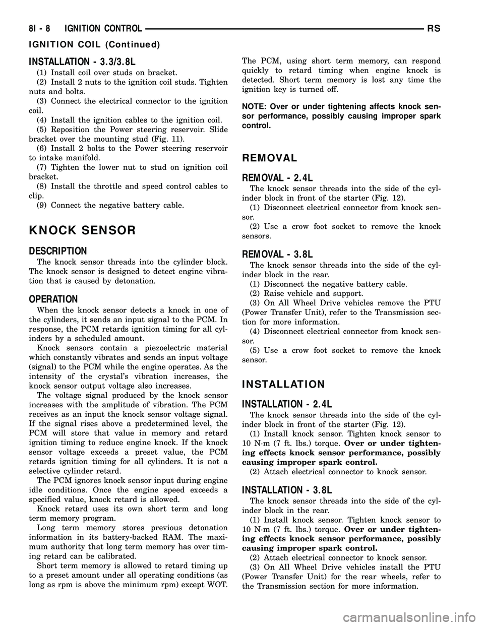
bracket over the mounting stud (Fig. 11).
(6) Install 2 bolts to the Power steering reservoir
to intake manifold.
(7) Tighten the lower nut to stud on ignition coil
bracket.
(8) Install the throttle and speed control cables to
clip.
(9) Connect the negative battery cable.
KNOCK SENSOR
DESCRIPTION
The knock sensor threads into the cylinder block.
The knock sensor is designed to detect engine vibra-
tion that is caused by detonation.
OPERATION
When the knock sensor detects a knock in one of
the cylinders, it sends an input signal to the PCM. In
response, the PCM retards ignition timing for all cyl-
inders by a scheduled amount.
Knock sensors contain a piezoelectric material
which constantly vibrates and sends an input voltage
(signal) to the PCM while the engine operates. As the
intensity of the crystal's vibration increases, the
knock sensor output voltage also increases.
The voltage signal produced by the knock sensor
increases with the amplitude of vibration. The PCM
receives as an input the knock sensor voltage signal.
If the signal rises above a predetermined level, the
PCM will store that value in memory and retard
ignition timing to reduce engine knock. If the knock
sensor voltage exceeds a preset value, the PCM
retards ignition timing for all cylinders. It is not a
selective cylinder retard.
The PCM ignores knock sensor input during engine
idle conditions. Once the engine speed exceeds a
specified value, knock retard is allowed.
Knock retard uses its own short term and long
term memory program.
Long term memory stores previous detonation
information in its battery-backed RAM. The maxi-
mum authority that long term memory has over tim-
ing retard can be calibrated.
Short term memory is allowed to retard timing up
to a preset amount under all operating conditions (as
long as rpm is above the minimum rpm) except WOT.The PCM, using short term memory, can respond
quickly to retard timing when engine knock is
detected. Short term memory is lost any time the
ignition key is turned off.
NOTE: Over or under tightening affects knock sen-
sor performance, possibly causing improper spark
control.
REMOVAL
REMOVAL - 2.4L
The knock sensor threads into the side of the cyl-
inder block in front of the starter (Fig. 12).
(1) Disconnect electrical connector from knock sen-
sor.
(2) Use a crow foot socket to remove the knock
sensors.
REMOVAL - 3.8L
The knock sensor threads into the side of the cyl-
inder block in the rear.
(1) Disconnect the negative battery cable.
(2) Raise vehicle and support.
(3) On All Wheel Drive vehicles remove the PTU
(Power Transfer Unit), refer to the Transmission sec-
tion for more information.
(4) Disconnect electrical connector from knock sen-
sor.
(5) Use a crow foot socket to remove the knock
sensor.
INSTALLATION
INSTALLATION - 2.4L
The knock sensor threads into the side of the cyl-
inder block in front of the starter (Fig. 12).
(1) Install knock sensor. Tighten knock sensor to
10 N´m (7 ft. lbs.) torque.Over or under tighten-
ing effects knock sensor performance, possibly
causing improper spark control.
(2) Attach electrical connector to knock sensor.
INSTALLATION - 3.8L
The knock sensor threads into the side of the cyl-
inder block in the rear.
(1) Install knock sensor. Tighten knock sensor to
10 N´m (7 ft. lbs.) torque.Over or under tighten-
ing effects knock sensor performance, possibly
causing improper spark control.
(2) Attach electrical connector to knock sensor.
(3) On All Wheel Drive vehicles install the PTU
(Power Transfer Unit) for the rear wheels, refer to
the Transmission section for more information.
8I - 8 IGNITION CONTROLRS
IGNITION COIL (Continued)
Page 499 of 2339
(12) Install the steering wheel (Refer to 19 -
STEERING/COLUMN/STEERING WHEEL -
INSTALLATION).
(13) Connect the 4±way harness connector to the
speed control/horn harness to the clockspring.
(14) Connect the 2±way connector to the remote
radio control harness.
(15) Install the driver airbag (Refer to 8 - ELEC-
TRICAL/RESTRAINTS/DRIVER AIRBAG - INSTAL-
LATION). Torque the two screws to 10 N´m (90 in.
lbs.).
WARNING: Do not connect the battery negative
cable (Refer to 8 - ELECTRICAL/RESTRAINTS -
DIAGNOSIS AND TESTING). Personal injury or
death may result if the system test is not performed
properly.
REMOVAL
(1) Position steering wheel and front wheels
straight ahead.
(2) Release hood latch and open hood.
(3) Disconnect and isolate the battery negative
cable.
(4)
WARNING: Wait two minutes for the airbag system
reserve capacitor to discharge before beginning
any airbag system or component service. Failure to
do so may result in accidental airbag deployment,
personal injury or death.
(5) Remove driver airbag from steering wheel
(Refer to 8 - ELECTRICAL/RESTRAINTS/DRIVER
AIRBAG - REMOVAL).
(6) Disconnect wire connectors from back of driver
airbag.
(7) Disconnect the 2±way connector from remote
radio control harness.
(8) Disconnect the 4±way harness connector from
the speed control/horn harness to the clockspring.
(9) Remove steering wheel (Refer to 19 - STEER-
ING/COLUMN/STEERING WHEEL - REMOVAL).
(10) Remove steering column shrouds and discon-
nect traction control wire connector (if equipped)
(Refer to 19 - STEERING/COLUMN/LOWER
SHROUD - REMOVAL).
(11) Disconnect 4-way and 6-way connectors
between the clockspring and the instrument panel
wiring harness.
(12) Remove clockspring from column assembly by
removing the two retaining screws that attach the
clock spring to the column.
INSTALLATION
(1) Install the clockspring on the column.
(2) Connect the 4-way and 6-way connectors
between the clockspring and the instrument panel
wiring harness.
(3) Install the steering column shrouds and con-
nect traction control wire connector (if equipped)
(Refer to 19 - STEERING/COLUMN/LOWER
SHROUD - INSTALLATION).
(4) Install the steering wheel (Refer to 19 -
STEERING/COLUMN/STEERING WHEEL -
INSTALLATION).
(5) Connect the 4±way harness connector to the
speed control/horn harness to the clockspring.
(6) Connect the 2±way connector to the remote
radio control harness (if equipped).
(7) Install the driver airbag (Refer to 8 - ELEC-
TRICAL/RESTRAINTS/DRIVER AIRBAG - INSTAL-
LATION). Torque the two screws to 10 N´m (90 in.
lbs.).
WARNING: Do not connect the battery negative
cable (Refer to 8 - ELECTRICAL/RESTRAINTS -
DIAGNOSIS AND TESTING - AIRBAG SYSTEM). Per-
sonal injury or death may result if the system test
is not performed first.
CURTAIN AIRBAG
DESCRIPTION
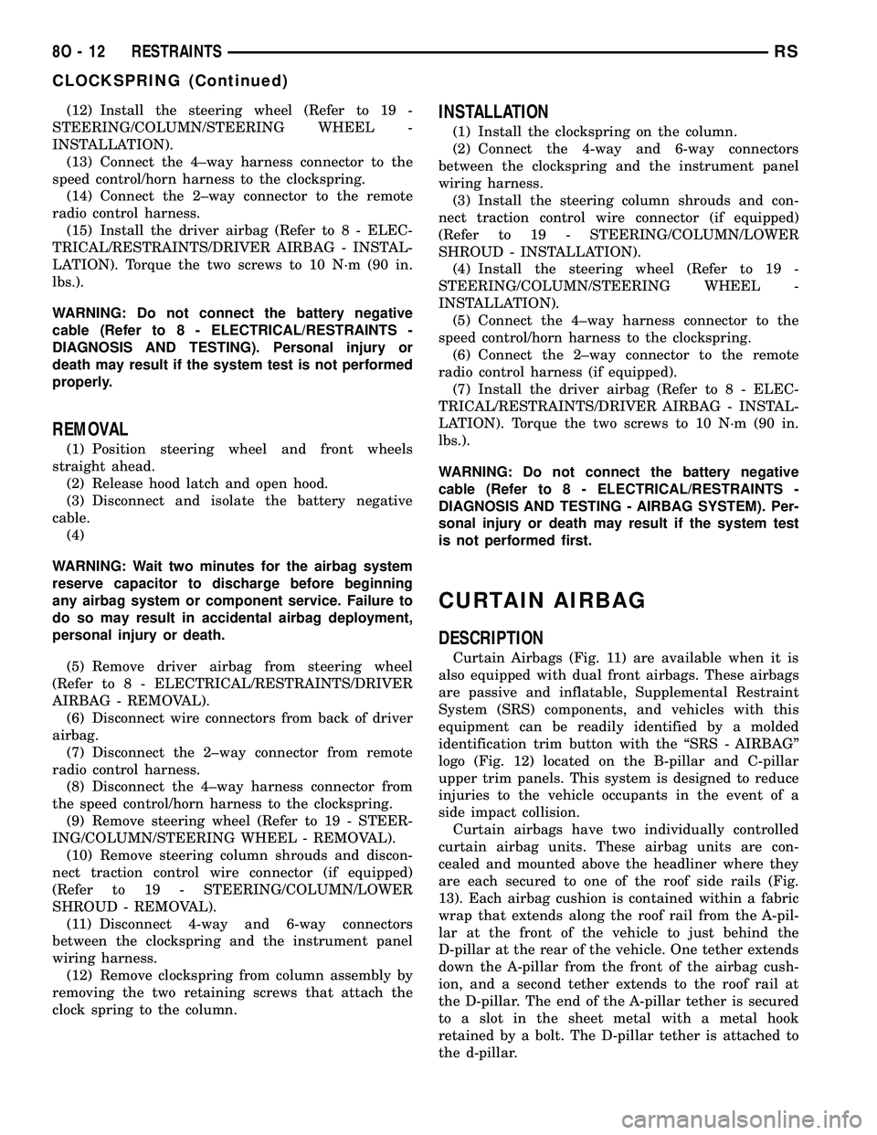
Curtain Airbags (Fig. 11) are available when it is
also equipped with dual front airbags. These airbags
are passive and inflatable, Supplemental Restraint
System (SRS) components, and vehicles with this
equipment can be readily identified by a molded
identification trim button with the ªSRS - AIRBAGº
logo (Fig. 12) located on the B-pillar and C-pillar
upper trim panels. This system is designed to reduce
injuries to the vehicle occupants in the event of a
side impact collision.
Curtain airbags have two individually controlled
curtain airbag units. These airbag units are con-
cealed and mounted above the headliner where they
are each secured to one of the roof side rails (Fig.
13). Each airbag cushion is contained within a fabric
wrap that extends along the roof rail from the A-pil-
lar at the front of the vehicle to just behind the
D-pillar at the rear of the vehicle. One tether extends
down the A-pillar from the front of the airbag cush-
ion, and a second tether extends to the roof rail at
the D-pillar. The end of the A-pillar tether is secured
to a slot in the sheet metal with a metal hook
retained by a bolt. The D-pillar tether is attached to
the d-pillar.
8O - 12 RESTRAINTSRS
CLOCKSPRING (Continued)
Page 505 of 2339
INSTALLATION
DEPLOYED AIRBAG
(1) Perform clean up procedure (Refer to 8 - ELEC-
TRICAL/RESTRAINTS - STANDARD PROCEDURE
- SERVICE AFTER AN AIRBAG DEPLOYMENT).
(2) Install a new steering column assembly and
lower steering column coupler (Refer to 19 - STEER-
ING/COLUMN - INSTALLATION).
(3) Install the new clockspring.
(4) Connect the 4-way and 6-way connectors
between the clockspring and the instrument panel
wiring harness.
(5) Install the steering column shrouds and con-
nect traction control wire connector (if equipped)
(Refer to 19 - STEERING/COLUMN/LOWER
SHROUD - INSTALLATION).
(6) Install the steering wheel (Refer to 19 -
STEERING/COLUMN/STEERING WHEEL -
INSTALLATION).
(7) Connect the 4±way harness connector to the
speed control/horn harness to the clockspring.
(8) Connect the 2±way connector to the remote
radio control harness.
(9) Install the driver airbag and the two screws
retaining the airbag. Tighten screws to 10 N´m (90
in. lbs.)
WARNING: Do not connect the battery negative
cable (Refer to 8 - ELECTRICAL/RESTRAINTS -
DIAGNOSIS AND TESTING - AIRBAG SYSTEM). Per-
sonal injury or death may result if the system test
is not performed first.
UNDEPLOYED AIRBAG
(1) Connect the harness connector on the driver
airbag trim cover (horn, speed controls) to the clock-
spring.
(2) Connect the squib connectors to the driver air-
bag.
(3) Position the driver airbag into the steering
wheel.
(4) Install the two screws retaining the airbag.
Tighten screws to 10 N´m (90 in. lbs.)
WARNING: Do not connect the battery negative
cable (Refer to 8 - ELECTRICAL/RESTRAINTS -
DIAGNOSIS AND TESTING - AIRBAG SYSTEM). Per-
sonal injury or death may result if the system test
is not performed first.
IMPACT SENSOR
DESCRIPTION
FRONT IMPACT SENSORS
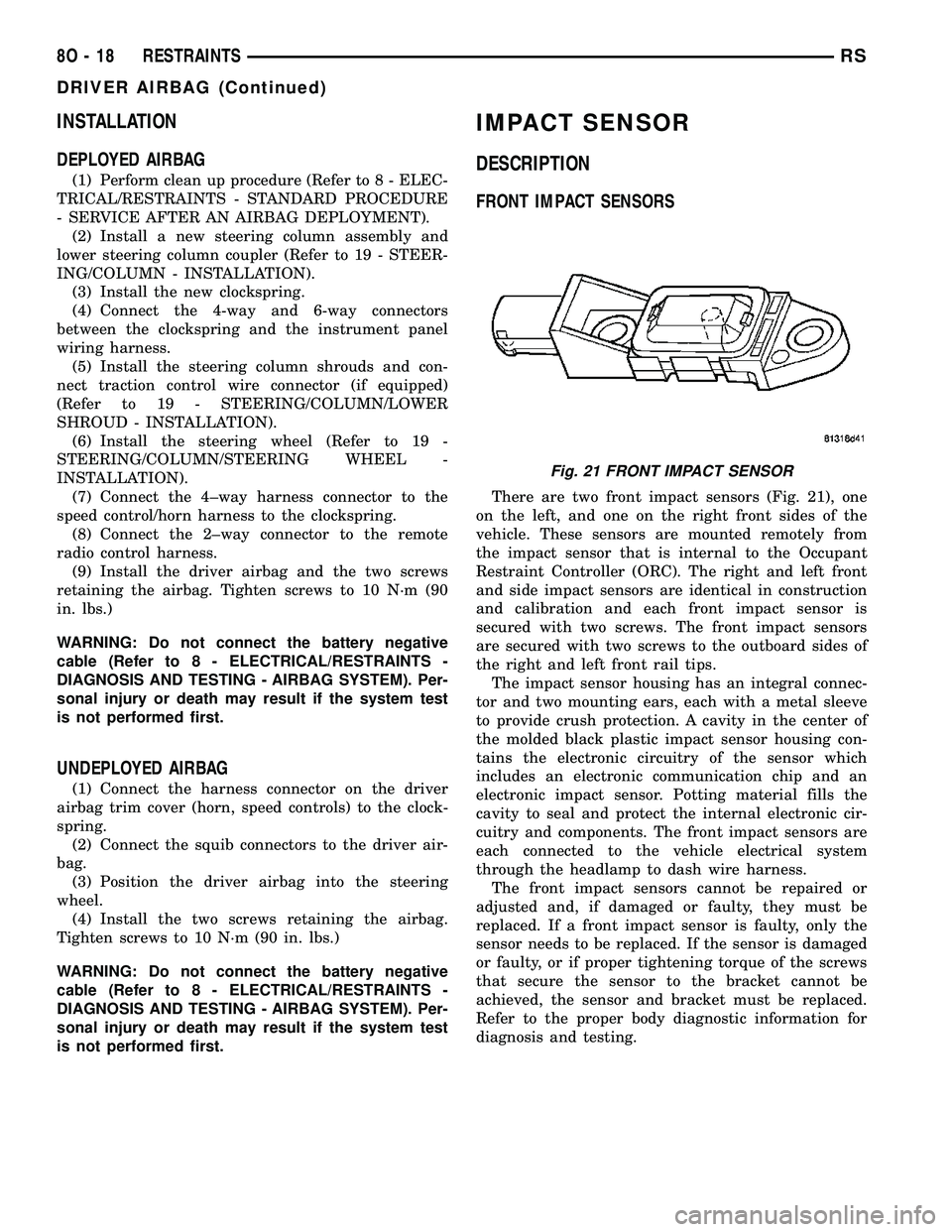
There are two front impact sensors (Fig. 21), one
on the left, and one on the right front sides of the
vehicle. These sensors are mounted remotely from
the impact sensor that is internal to the Occupant
Restraint Controller (ORC). The right and left front
and side impact sensors are identical in construction
and calibration and each front impact sensor is
secured with two screws. The front impact sensors
are secured with two screws to the outboard sides of
the right and left front rail tips.
The impact sensor housing has an integral connec-
tor and two mounting ears, each with a metal sleeve
to provide crush protection. A cavity in the center of
the molded black plastic impact sensor housing con-
tains the electronic circuitry of the sensor which
includes an electronic communication chip and an
electronic impact sensor. Potting material fills the
cavity to seal and protect the internal electronic cir-
cuitry and components. The front impact sensors are
each connected to the vehicle electrical system
through the headlamp to dash wire harness.
The front impact sensors cannot be repaired or
adjusted and, if damaged or faulty, they must be
replaced. If a front impact sensor is faulty, only the
sensor needs to be replaced. If the sensor is damaged
or faulty, or if proper tightening torque of the screws
that secure the sensor to the bracket cannot be
achieved, the sensor and bracket must be replaced.
Refer to the proper body diagnostic information for
diagnosis and testing.
Fig. 21 FRONT IMPACT SENSOR
8O - 18 RESTRAINTSRS
DRIVER AIRBAG (Continued)
Page 508 of 2339

WARNING: Wait two minutes for the system reserve
capacitor to discharge before beginning any airbag
component service. Personal injury or death may
result.
(3) Open sliding door to the fullest open position.
(4) Remove the two retaining screws to the impact
sensor (Fig. 27).
(5) Disconnect the electrical connector from the
impact sensor and remove from vehicle (Fig. 27).
QUARTER PANEL MOUNTED
(1) Open hood, disconnect and isolate the battery
negative cable.
(2)
WARNING: Wait two minutes for the system reserve
capacitor to discharge before beginning any airbag
component service. Personal injury or death may
result.
(3) Remove the quarter trim panel for the side of
the vehicle that you are replacing the side impact
sensor (Refer to 23 - BODY/INTERIOR/QUARTER
TRIM PANEL - REMOVAL).
(4) Remove the two retaining screws to the impact
sensor (Fig. 28).
(5) Disconnect the electrical connector from the
impact sensor and remove from vehicle (Fig. 28).
INSTALLATION
FRONT IMPACT SENSOR
(1) Position sensor in vehicle (Fig. 24).
(2) Install the two retaining screws to the impact
sensor (Fig. 24). Torque screws to 7 N´m (62 in. lbs.).
(3) Connect electrical connector (Fig. 24).
(4) Lower vehicle from hoist.
WARNING: Do not connect the battery negative
cable (Refer to 8 - ELECTRICAL/RESTRAINTS -
DIAGNOSIS AND TESTING - AIRBAG SYSTEM). Per-
sonal injury or death may result if the system test
is not performed first.
(5) Verify vehicle and system operation.
(6) Close hood.
SIDE IMPACT SENSORS
B-PILLAR MOUNTED
(1) Position sensor bracket in vehicle (Fig. 25).
(2) Install the four retaining screws to the impact
sensor bracket (Fig. 25). Torque screws to 7 N´m (62
in. lbs.).
(3) Connect the electrical connector (Fig. 25).
(4) Install the B-pillar lower trim for the side of
the vehicle that you are replacing the side impact
sensor (Refer to 23 - BODY/INTERIOR/B-PILLAR
LOWER TRIM - INSTALLATION).
Fig. 27 2ND ROW SIDE IMPACT SENSOR
1 - 2ND ROW SIDE IMPACT SENSOR ELECTRICAL CONNECTOR
2 - 2ND ROW SIDE IMPACT SENSOR RETAINING SCREWS
3 - SLIDING DOOR LOWER ROLLER ARM
Fig. 28 3RD ROW SIDE IMPACT SENSOR
1 - 3RD ROW SIDE IMPACT SENSOR
2 - 3RD ROW SIDE IMPACT SENSOR MOUNTING SCREWS
3 - REAR SPEAKER
4 - REAR WHEEL WELL
RSRESTRAINTS8O-21
IMPACT SENSOR (Continued)
Page 517 of 2339

WARNING: Never replace both the Occupant
Restraint Controller (ORC) and the Occupant Clas-
sification Module (OCM) at the same time. If both
require replacement, replace one, then perform the
Airbag System test (Refer to 8 - ELECTRICAL/RE-
STRAINTS - DIAGNOSIS AND TESTING - AIRBAG
SYSTEM) before replacing the other. Both the ORC
and the OCM store Occupant Classification System
(OCS) calibration data, which they transfer to one
another when one of them is replaced. If both are
replaced at the same time, an irreversible fault will
be set in both modules and the OCS may malfunc-
tion and result in personal injury or death.
(1) Install the ORC into vehicle (Fig. 39).
(2) Connect the wire connector to the ORC (Fig.
39).
(3) Install three bolts holding ORC to floor bracket
(Fig. 39). Torque bolts to 7.3 - 9.6 N´m (65 to 85 in.
lbs.)
(4) Install the storage bin onto the instrument
panel (Refer to 23 - BODY/INSTRUMENT PANEL/
STORAGE BIN - INSTALLATION).
WARNING: Do not connect the battery negative
cable (Refer to 8 - ELECTRICAL/RESTRAINTS -
DIAGNOSIS AND TESTING - AIRBAG SYSTEM). Per-
sonal injury or death may result if the system test
is not performed first.
(5) Verify vehicle and system operation.
(6) Close hood.
PASSENGER AIRBAG
DESCRIPTION
WARNING: Never disassemble the passenger air-
bag. The passenger airbag has no serviceable
parts. If tampered with internally, the airbag could
deploy and result in personal injury or death.
The Passenger Airbag is located beneath the
instrument panel and pad assembly. The airbag is
mounted to the back side of the instrument panel
reinforcement.
The instrument panel top pad is the most visible
part of the passenger airbag system. Located under
the instrument panel top pad are the airbag door, the
passenger airbag cushion and the airbag cushion
supporting components.
The passenger airbag includes a magnesium hous-
ing within which the cushion and inflator are
mounted and sealed.
Following a passenger airbag deployment, the pas-
senger airbag and the instrument panel must bereplaced. The passenger airbag cannot be repaired,
and must be replaced if deployed or damaged in any
way.
OPERATION
The passenger airbag is equipped with two infla-
tors, each with three levels of pressure output. The
inflators seal the hole in the airbag cushion so it can
discharge the gas it produces directly into the cush-
ion when supplied with the proper electrical signal.
Following an airbag deployment, the airbag cushion
quickly deflates by venting this gas through the
cushion material towards the instrument panel.
The passenger airbag is secured with screws to the
instrument panel beneath the instrument panel top
pad and above the glove box opening. The instrument
panel top pad above the glove box opening conceals
the airbag door and a predetermined hinge line
beneath its decorative cover. Upon airbag deploy-
ment, the top pad will bend at the hinge line and the
door will fold back out of the way onto the top of the
instrument panel.
When the front airbag system is deployed, the fol-
lowingMUSTbe replaced:
²Complete Steering Column Assembly.
²Lower Steering Column Coupler.
²Steering Wheel.
²Clock Spring.
²Driver Airbag.
²Passenger Airbag.
²Upper Instrument Panel with Pad.
CARE OF UNDEPLOYED AIRBAGS
Airbags must be stored in their original special
container until used for service. At no time should a
source of electricity be permitted near the inflator on
the back of an airbag. When carrying or handling an
undeployed airbag, the trim side of the airbag should
be pointing away from the body to minimize possibil-
ity of injury if accidental deployment occurs. Do not
place undeployed airbag face down on a solid surface,
the airbag will propel into the air if accidental
deployment occurs.
REMOVAL
DEPLOYED AIRBAG
(1) Open hood.
(2) Disconnect and isolate the battery negative
cable.
(3)
8O - 30 RESTRAINTSRS
OCCUPANT RESTRAINT CONTROLLER (Continued)
Page 532 of 2339

SPEED CONTROL
TABLE OF CONTENTS
page page
SPEED CONTROL
DESCRIPTION..........................1
OPERATION
OPERATION..........................1
OPERATION - INTERACTIVE SPEED
CONTROL (4 Speed EATX Only)...........2
DIAGNOSIS AND TESTING - ROAD TEST.....3
SPECIFICATIONS - TORQUE...............3
CABLE
DESCRIPTION..........................4
OPERATION............................4
REMOVAL.............................4
INSTALLATION..........................4
SERVO
DESCRIPTION..........................4OPERATION............................4
REMOVAL.............................4
INSTALLATION..........................4
SWITCH
DESCRIPTION..........................5
OPERATION............................5
REMOVAL.............................5
INSTALLATION..........................6
VACUUM RESERVOIR
DESCRIPTION..........................6
OPERATION............................6
REMOVAL.............................6
INSTALLATION..........................6
SPEED CONTROL
DESCRIPTION
The speed control system is electronically con-
trolled and vacuum operated. The electronic control
is integrated into the Powertrain Control Module.
The controls are located on the steering wheel. The
ON/OFF, and SET buttons are located on the left side
of the airbag module. The RESUME/ACCEL, CAN-
CEL and COAST buttons are located on the right
side of the airbag module (Fig. 1).The system is designed to operate at speeds above
30 mph (48 km/h).
WARNING: THE USE OF SPEED CONTROL IS NOT
RECOMMENDED WHEN DRIVING CONDITIONS DO
NOT PERMIT MAINTAINING A CONSTANT SPEED,
SUCH AS IN HEAVY TRAFFIC OR ON ROADS THAT
ARE WINDING, ICY, SNOW COVERED, OR SLIP-
PERY.
OPERATION
OPERATION
When speed control is activated by depressing the
ON switch, the PCM allows a set speed to be stored
in RAM for speed control. To store a set speed,
depress and release the SET switch while the vehicle
is moving at a speed between 25 and 85 mph. In
order for the speed control to engage, the brakes can-
not be applied, nor can the gear selector be indicat-
ing the transmission is in Park or Neutral (ATX) or
1st/2nd gear (MTX). The speed control can be disen-
gaged manually by:
²Stepping on the brake pedal
²Depressing the OFF switch
²Depressing the CANCEL switch.
²Depressing the clutch pedal
²Operating in 1st or 2nd gear (autostick, if
equipped)
Fig. 1 SPEED CONTROL SWITCHES - Typical
RSSPEED CONTROL8P-1
Page 558 of 2339

INSTALLATION
(1) Push filler neck and front washer hose through
the opening in the front fender side shield. Connect
the reservoir to the body mount by lowering the res-
ervoir down.
(2) Install the two reservoir mounting screws.
Torque screws to 8.5 - 11.3 N´m (75 - 100 in. lbs.).
(3) Connect the electrical body harness connectors
to the washer pump motor and the fluid level sensor.
Slide the red lock on the connector to the closed or
locked position.
(4) Assure that washer is properly routed to pre-
vent pinching and possible inoperative washers.
(5) Install the left right front wheelhouse splash
shield (Refer to 23 - BODY/EXTERIOR/WHEEL-
HOUSE SPLASH SHIELD - INSTALLATION).
(6) Install the right front wheel and tire assembly
(Refer to 22 - TIRES/WHEELS - INSTALLATION).
(7) lower vehicle from hoist or jack stands.
(8) Install the filler tube screw. Torque screw to 8.5
- 11.3 N´m (75 - 100 in. lbs.).
(9) Connect the washer hose to the hose clip
located on the front fender side shield.
(10) Connect the washer hose at the in-line con-
nector forward of the cowl grille.
(11) Install the engine fresh air housing inside the
engine compartment (Refer to 9 - ENGINE/AIR
INTAKE SYSTEM/AIR CLEANER HOUSING -
INSTALLATION).
(12) Connect the battery negative cable.
(13) Verify system operation.
WIPER BLADES
REMOVAL
(1) Lift the wiper arm away from the glass.
(2) Disengage the release tab holding the wiper
blade to the wiper arm and remove the wiper blade
from the wiper arm (Fig. 5) and (Fig. 6).
CLEANING
Wiper blades exposed to the weather for a long
period of time tend to lose their wiping effectiveness.
Periodic cleaning of the wiper blade is recommended
to remove the accumulation of salt and road grime.
The wiper blades, arms and windshield should be
cleaned with a sponge or cloth and a mild detergent
or nonabrasive cleaner. If the wiper blades continue
to streak or smear, they should be replaced. The
wiper blade should run smoothly across the wind-
shield in both directions. The wiper blade should
slightly roll over center when the blade reverses
direction. A wiper blade insert that has lost flexibility
or a wiper arm that has lost spring tension, will
cause the blade to skip or chatter across the wind-
shield. If the wiper blades are new and the wiper
arm spring tension is OK and a chattering sound is
emitted from the wiper(s), the wiper blade is not roll-
ing over center. If this condition exists, (refer to 8 -
ELECTRICAL/WIPERS/WASHERS/WIPER ARMS -
ADJUSTMENTS).
INSTALLATION
(1) Position the blade onto the arm.
(2) Engage the blade to the retainer by pulling up
on the blade until the tabs snap into position (Fig. 5).
WIPER LINKAGE
REMOVAL
(1) Remove the front windshield wiper unit from
vehicle (Refer to 8 - ELECTRICAL/WIPERS/WASH-
ERS/WIPER MODULE - REMOVAL).
(2) Place the wiper unit on a suitable work sur-
face.
(3) Remove nuts holding the cowl cover brackets to
the wiper unit.
(4) Remove cowl cover brackets from the wiper
unit.
(5) Remove nuts holding linkage to the wiper unit.
(6) Remove the wiper linkage from the wiper unit.
Fig. 5 WINDSHIELD WIPER BLADE
1 - RELEASE TAB
Fig. 6 REAR WIPER
1 - WIPER ARM
2 - BLADE LATCH
RSWIPERS/WASHERS8R-13
WASHER RESERVOIR (Continued)
Page 561 of 2339
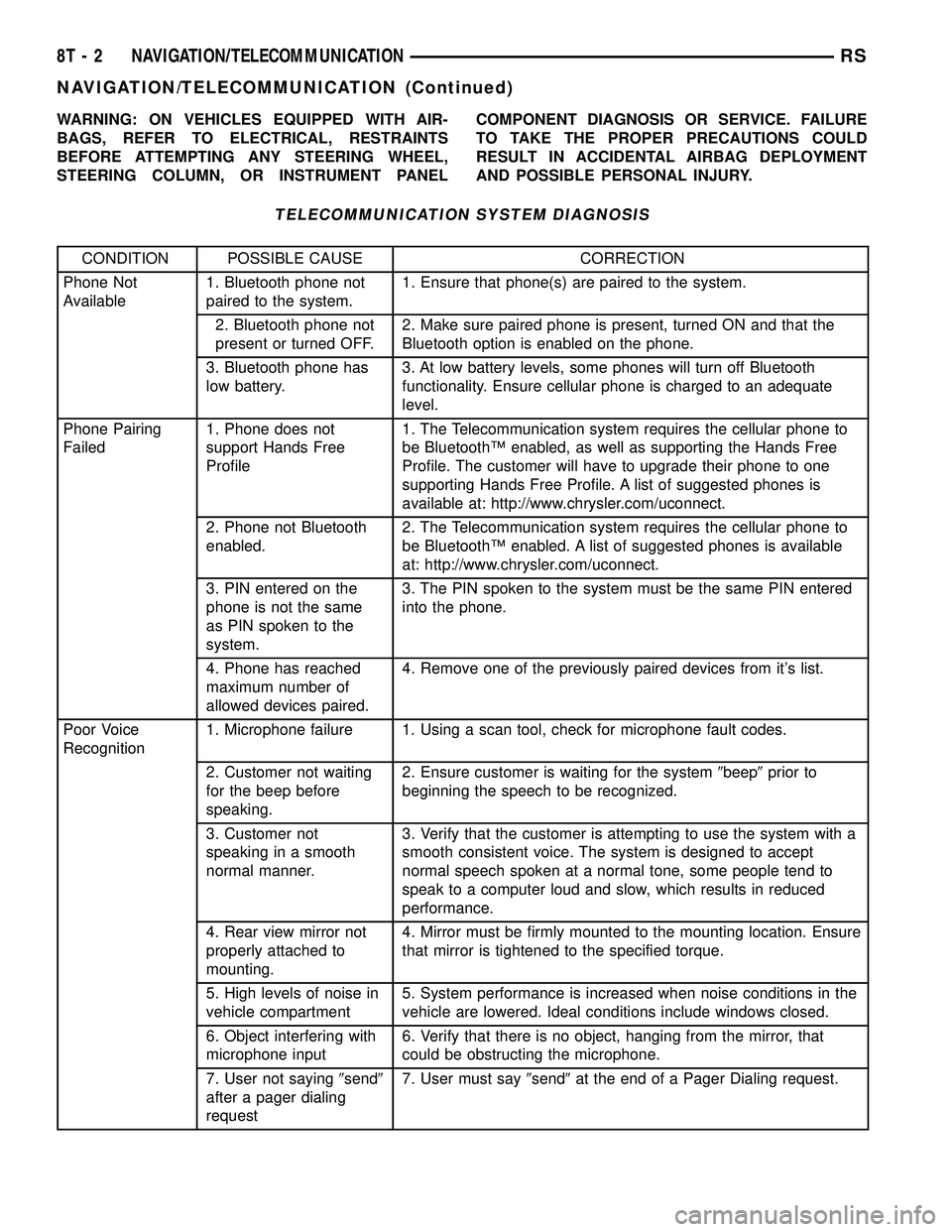
WARNING: ON VEHICLES EQUIPPED WITH AIR-
BAGS, REFER TO ELECTRICAL, RESTRAINTS
BEFORE ATTEMPTING ANY STEERING WHEEL,
STEERING COLUMN, OR INSTRUMENT PANELCOMPONENT DIAGNOSIS OR SERVICE. FAILURE
TO TAKE THE PROPER PRECAUTIONS COULD
RESULT IN ACCIDENTAL AIRBAG DEPLOYMENT
AND POSSIBLE PERSONAL INJURY.
TELECOMMUNICATION SYSTEM DIAGNOSIS
CONDITION POSSIBLE CAUSE CORRECTION
Phone Not
Available1. Bluetooth phone not
paired to the system.1. Ensure that phone(s) are paired to the system.
2. Bluetooth phone not
present or turned OFF.2. Make sure paired phone is present, turned ON and that the
Bluetooth option is enabled on the phone.
3. Bluetooth phone has
low battery.3. At low battery levels, some phones will turn off Bluetooth
functionality. Ensure cellular phone is charged to an adequate
level.
Phone Pairing
Failed1. Phone does not
support Hands Free
Profile1. The Telecommunication system requires the cellular phone to
be BluetoothŸ enabled, as well as supporting the Hands Free
Profile. The customer will have to upgrade their phone to one
supporting Hands Free Profile. A list of suggested phones is
available at: http://www.chrysler.com/uconnect.
2. Phone not Bluetooth
enabled.2. The Telecommunication system requires the cellular phone to
be BluetoothŸ enabled. A list of suggested phones is available
at: http://www.chrysler.com/uconnect.
3. PIN entered on the
phone is not the same
as PIN spoken to the
system.3. The PIN spoken to the system must be the same PIN entered
into the phone.
4. Phone has reached
maximum number of
allowed devices paired.4. Remove one of the previously paired devices from it's list.
Poor Voice
Recognition1. Microphone failure 1. Using a scan tool, check for microphone fault codes.
2. Customer not waiting
for the beep before
speaking.2. Ensure customer is waiting for the system9beep9prior to
beginning the speech to be recognized.
3. Customer not
speaking in a smooth
normal manner.3. Verify that the customer is attempting to use the system with a
smooth consistent voice. The system is designed to accept
normal speech spoken at a normal tone, some people tend to
speak to a computer loud and slow, which results in reduced
performance.
4. Rear view mirror not
properly attached to
mounting.4. Mirror must be firmly mounted to the mounting location. Ensure
that mirror is tightened to the specified torque.
5. High levels of noise in
vehicle compartment5. System performance is increased when noise conditions in the
vehicle are lowered. Ideal conditions include windows closed.
6. Object interfering with
microphone input6. Verify that there is no object, hanging from the mirror, that
could be obstructing the microphone.
7. User not saying9send9
after a pager dialing
request7. User must say9send9at the end of a Pager Dialing request.
8T - 2 NAVIGATION/TELECOMMUNICATIONRS
NAVIGATION/TELECOMMUNICATION (Continued)
Page 1184 of 2339
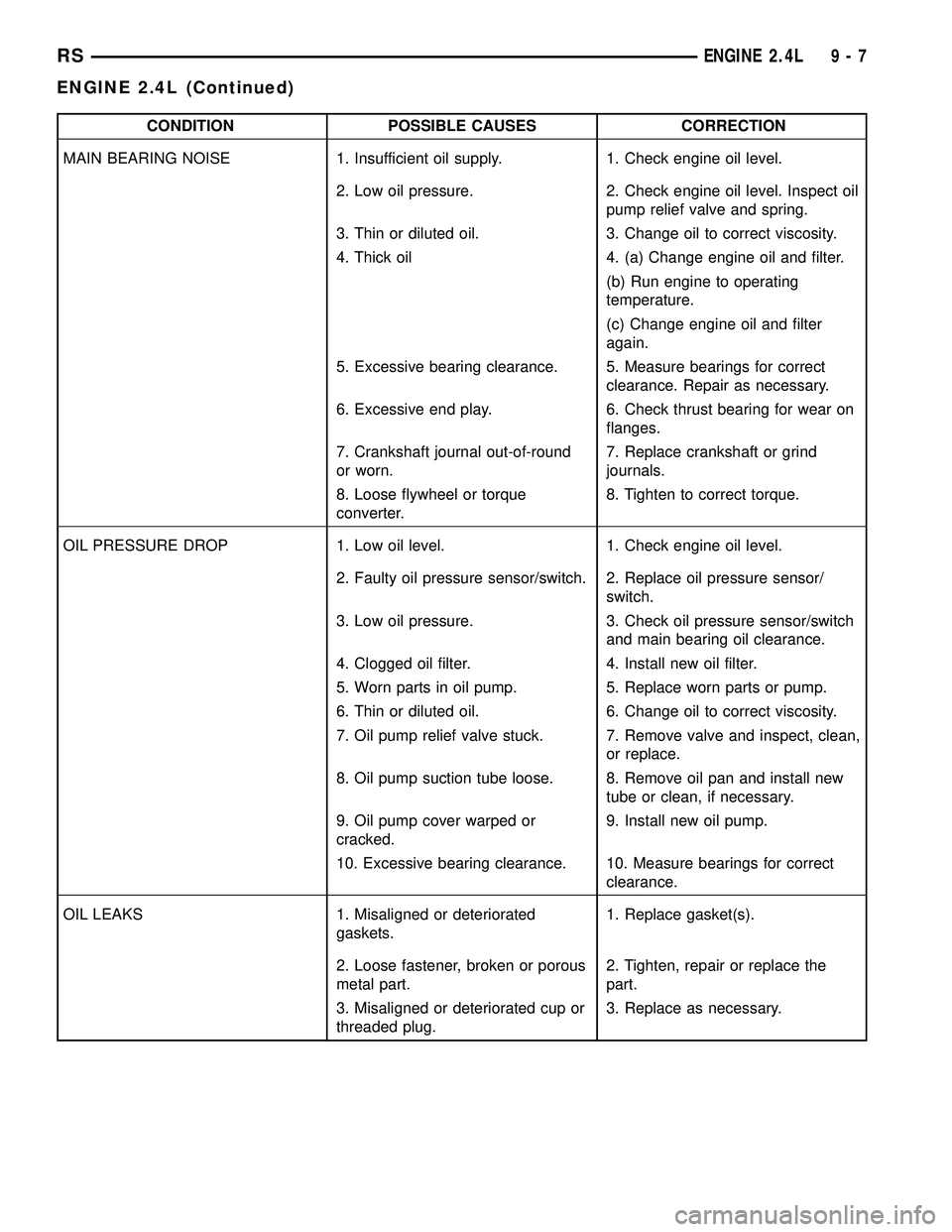
CONDITION POSSIBLE CAUSES CORRECTION
MAIN BEARING NOISE 1. Insufficient oil supply. 1. Check engine oil level.
2. Low oil pressure. 2. Check engine oil level. Inspect oil
pump relief valve and spring.
3. Thin or diluted oil. 3. Change oil to correct viscosity.
4. Thick oil 4. (a) Change engine oil and filter.
(b) Run engine to operating
temperature.
(c) Change engine oil and filter
again.
5. Excessive bearing clearance. 5. Measure bearings for correct
clearance. Repair as necessary.
6. Excessive end play. 6. Check thrust bearing for wear on
flanges.
7. Crankshaft journal out-of-round
or worn.7. Replace crankshaft or grind
journals.
8. Loose flywheel or torque
converter.8. Tighten to correct torque.
OIL PRESSURE DROP 1. Low oil level. 1. Check engine oil level.
2. Faulty oil pressure sensor/switch. 2. Replace oil pressure sensor/
switch.
3. Low oil pressure. 3. Check oil pressure sensor/switch
and main bearing oil clearance.
4. Clogged oil filter. 4. Install new oil filter.
5. Worn parts in oil pump. 5. Replace worn parts or pump.
6. Thin or diluted oil. 6. Change oil to correct viscosity.
7. Oil pump relief valve stuck. 7. Remove valve and inspect, clean,
or replace.
8. Oil pump suction tube loose. 8. Remove oil pan and install new
tube or clean, if necessary.
9. Oil pump cover warped or
cracked.9. Install new oil pump.
10. Excessive bearing clearance. 10. Measure bearings for correct
clearance.
OIL LEAKS 1. Misaligned or deteriorated
gaskets.1. Replace gasket(s).
2. Loose fastener, broken or porous
metal part.2. Tighten, repair or replace the
part.
3. Misaligned or deteriorated cup or
threaded plug.3. Replace as necessary.
RSENGINE 2.4L9-7
ENGINE 2.4L (Continued)