brake fluid CHRYSLER CARAVAN 2005 Repair Manual
[x] Cancel search | Manufacturer: CHRYSLER, Model Year: 2005, Model line: CARAVAN, Model: CHRYSLER CARAVAN 2005Pages: 2339, PDF Size: 59.69 MB
Page 212 of 2339
For more information, (Refer to 5 - BRAKES/HY-
DRAULIC/MECHANICAL/ICU (INTEGRATED CON-
TROL UNIT) - DESCRIPTION)
OPERATION
For information on the operation of the HCU as a
whole, refer to Hydraulic Circuits And Valve Opera-
tion which can be found elsewhere in this section.
For information on the operation of the components
within the HCU, refer to the following three topics.
VALVES AND SOLENOIDS
The valve block contains four inlet valves and four
outlet valves. The inlet valves are spring-loaded in
the open position and the outlet valves are spring-
loaded in the closed position during normal braking.
The fluid is allowed to flow from the master cylinder
to the wheel brakes.
During an ABS stop, these valves cycle to maintain
the proper slip ratio for each wheel. The inlet valve
closes preventing further pressure increase and the
outlet valve opens to provide a path from the wheel
brake to the HCU accumulators and pump/motor.
This releases (decays) pressure from the wheel brake,
thus releasing the wheel from excessive slippage.
Once the wheel is no longer slipping, the outlet valve
is closed and the inlet valve is opened to reapply
(build) pressure.
On vehicles with traction control, there is an extra
set of valves and solenoids. The ASR valves, mounted
in the HCU valve block, are normally in the open
position and close only when the traction control is
applied.
These isolator valves are used to isolate the rear
(non-driving) wheels of the vehicle from the hydraulic
pressure that the HCU pump/motor is sending to the
front (driving) wheels when traction control is being
applied. The rear brakes need to be isolated from the
master cylinder when traction control is being
applied so the rear wheels do not drag. For more
information, refer to Traction Control System in this
section.
BRAKE FLUID ACCUMULATORS
There are two fluid accumulators in the HCU±one
for the primary hydraulic circuit and one for the sec-
ondary hydraulic circuit. Each hydraulic circuit uses
a 5 cc accumulator.
The fluid accumulators temporarily store brake
fluid that is removed from the wheel brakes during
an ABS cycle. This stored fluid is used by the pump/
motor to provide build pressure for the brake hydrau-
lic system. When the antilock stop is complete, the
accumulators are drained by the pump/motor.
On ABS-only vehicles, there is a mini-accumulator
on the secondary hydraulic circuit that protects the
master cylinder seals during an ABS stop, and there
is a noise dampening chamber on the primary circuit.
On ABS with traction control vehicles, there are
two noise dampening chambers in the HCU.
PUMP/MOTOR
There are two pump assemblies in the HCUÐone
for the primary hydraulic circuit and one for the sec-
ondary hydraulic circuit. Both pumps are driven by a
common electric motor. This DC-type motor is inte-
gral to the HCU and is controlled by the CAB.
The pump/motor provides the extra amount of
brake fluid needed during antilock braking. Brake
fluid is released to the accumulators when the outlet
valve is opened during an antilock stop. The pump
mechanism consists of two opposing pistons operated
by an eccentric camshaft. In operation, one piston
draws fluid from the accumulators, and the opposing
piston pumps fluid to the master cylinder circuits.
When the antilock stop is complete, the pump/motor
drains the accumulators.
The CAB may turn on the pump/motor when an
antilock stop is detected. The pump/motor continues
to run during the antilock stop and is turned off after
the stop is complete. Under some conditions, the
pump/motor runs to drain the accumulators during
the next drive-off.
The pump/motor is not a serviceable item; if it
requires replacement, the HCU must be replaced.
RSBRAKES - ABS5 - 101
HCU (HYDRAULIC CONTROL UNIT) (Continued)
Page 213 of 2339
ICU (INTEGRATED CONTROL
UNIT)
DESCRIPTION
The hydraulic control unit (HCU) and the control-
ler antilock brake (CAB) used with this antilock
brake system are combined (integrated) into one
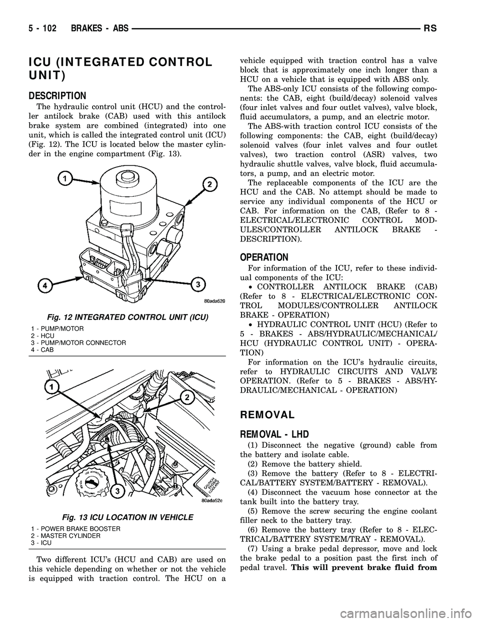
unit, which is called the integrated control unit (ICU)
(Fig. 12). The ICU is located below the master cylin-
der in the engine compartment (Fig. 13).
Two different ICU's (HCU and CAB) are used on
this vehicle depending on whether or not the vehicle
is equipped with traction control. The HCU on avehicle equipped with traction control has a valve
block that is approximately one inch longer than a
HCU on a vehicle that is equipped with ABS only.
The ABS-only ICU consists of the following compo-
nents: the CAB, eight (build/decay) solenoid valves
(four inlet valves and four outlet valves), valve block,
fluid accumulators, a pump, and an electric motor.
The ABS-with traction control ICU consists of the
following components: the CAB, eight (build/decay)
solenoid valves (four inlet valves and four outlet
valves), two traction control (ASR) valves, two
hydraulic shuttle valves, valve block, fluid accumula-
tors, a pump, and an electric motor.
The replaceable components of the ICU are the
HCU and the CAB. No attempt should be made to
service any individual components of the HCU or
CAB. For information on the CAB, (Refer to 8 -
ELECTRICAL/ELECTRONIC CONTROL MOD-
ULES/CONTROLLER ANTILOCK BRAKE -
DESCRIPTION).
OPERATION
For information of the ICU, refer to these individ-
ual components of the ICU:
²CONTROLLER ANTILOCK BRAKE (CAB)
(Refer to 8 - ELECTRICAL/ELECTRONIC CON-
TROL MODULES/CONTROLLER ANTILOCK
BRAKE - OPERATION)
²HYDRAULIC CONTROL UNIT (HCU) (Refer to
5 - BRAKES - ABS/HYDRAULIC/MECHANICAL/
HCU (HYDRAULIC CONTROL UNIT) - OPERA-
TION)
For information on the ICU's hydraulic circuits,
refer to HYDRAULIC CIRCUITS AND VALVE
OPERATION. (Refer to 5 - BRAKES - ABS/HY-
DRAULIC/MECHANICAL - OPERATION)
REMOVAL
REMOVAL - LHD
(1) Disconnect the negative (ground) cable from
the battery and isolate cable.
(2) Remove the battery shield.
(3) Remove the battery (Refer to 8 - ELECTRI-
CAL/BATTERY SYSTEM/BATTERY - REMOVAL).
(4) Disconnect the vacuum hose connector at the
tank built into the battery tray.
(5) Remove the screw securing the engine coolant
filler neck to the battery tray.
(6) Remove the battery tray (Refer to 8 - ELEC-
TRICAL/BATTERY SYSTEM/TRAY - REMOVAL).
(7) Using a brake pedal depressor, move and lock
the brake pedal to a position past the first inch of
pedal travel.This will prevent brake fluid from
Fig. 12 INTEGRATED CONTROL UNIT (ICU)
1 - PUMP/MOTOR
2 - HCU
3 - PUMP/MOTOR CONNECTOR
4 - CAB
Fig. 13 ICU LOCATION IN VEHICLE
1 - POWER BRAKE BOOSTER
2 - MASTER CYLINDER
3 - ICU
5 - 102 BRAKES - ABSRS
Page 215 of 2339
CHANICAL/ICU (INTEGRATED CONTROL UNIT) -
DISASSEMBLY).
REMOVAL - RHD
NOTE: Before proceeding, (Refer to 5 - BRAKES -
WARNING)(Refer to 5 - BRAKES - CAUTION)
(1) Disconnect the negative (ground) cable from
the battery and isolate cable.
(2) Using a brake pedal depressor, move and lock
the brake pedal to a position past the first inch of
pedal travel.This will prevent brake fluid from
draining out of the master cylinder when the
brake tubes are removed from the HCU.
(3) Raise vehicle. (Refer to LUBRICATION &
MAINTENANCE/HOISTING - STANDARD PROCE-
DURE)
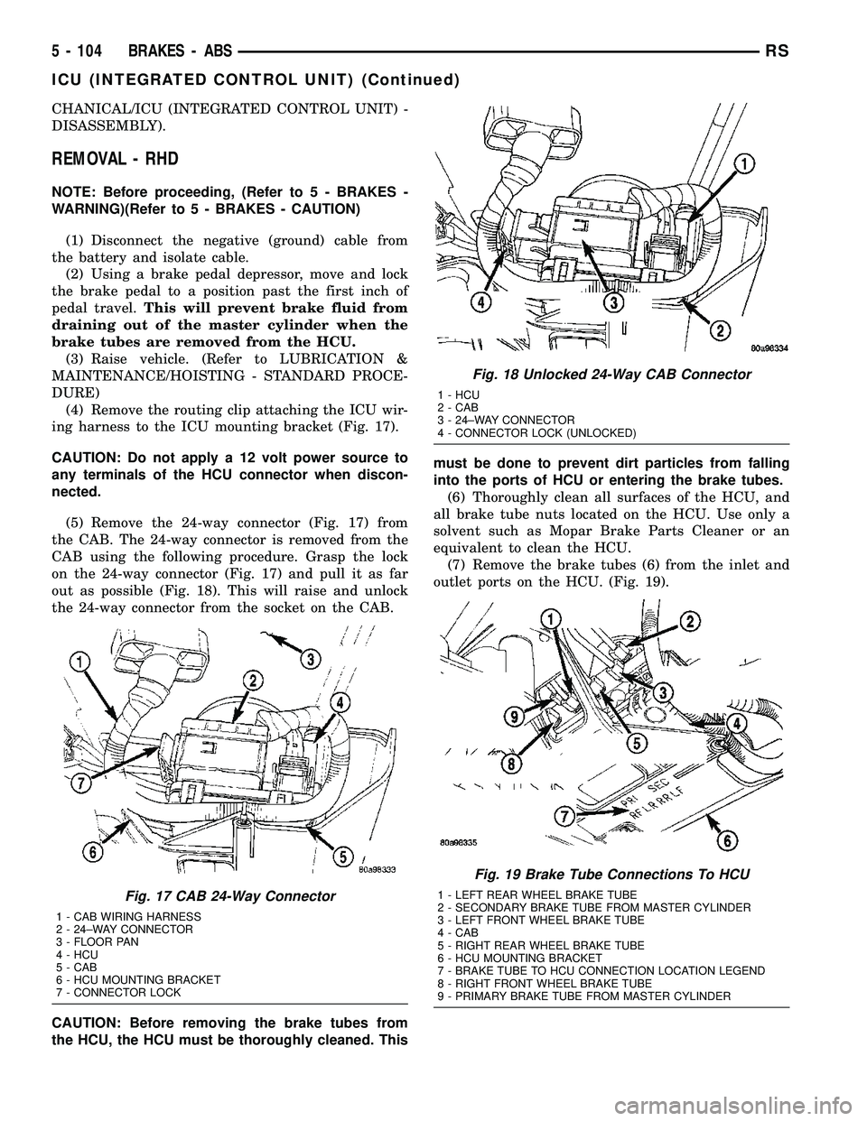
(4) Remove the routing clip attaching the ICU wir-
ing harness to the ICU mounting bracket (Fig. 17).
CAUTION: Do not apply a 12 volt power source to
any terminals of the HCU connector when discon-
nected.
(5) Remove the 24-way connector (Fig. 17) from
the CAB. The 24-way connector is removed from the
CAB using the following procedure. Grasp the lock
on the 24-way connector (Fig. 17) and pull it as far
out as possible (Fig. 18). This will raise and unlock
the 24-way connector from the socket on the CAB.
CAUTION: Before removing the brake tubes from
the HCU, the HCU must be thoroughly cleaned. Thismust be done to prevent dirt particles from falling
into the ports of HCU or entering the brake tubes.
(6) Thoroughly clean all surfaces of the HCU, and
all brake tube nuts located on the HCU. Use only a
solvent such as Mopar Brake Parts Cleaner or an
equivalent to clean the HCU.
(7) Remove the brake tubes (6) from the inlet and
outlet ports on the HCU. (Fig. 19).
Fig. 17 CAB 24-Way Connector
1 - CAB WIRING HARNESS
2 - 24±WAY CONNECTOR
3 - FLOOR PAN
4 - HCU
5 - CAB
6 - HCU MOUNTING BRACKET
7 - CONNECTOR LOCK
Fig. 18 Unlocked 24-Way CAB Connector
1 - HCU
2 - CAB
3 - 24±WAY CONNECTOR
4 - CONNECTOR LOCK (UNLOCKED)
Fig. 19 Brake Tube Connections To HCU
1 - LEFT REAR WHEEL BRAKE TUBE
2 - SECONDARY BRAKE TUBE FROM MASTER CYLINDER
3 - LEFT FRONT WHEEL BRAKE TUBE
4 - CAB
5 - RIGHT REAR WHEEL BRAKE TUBE
6 - HCU MOUNTING BRACKET
7 - BRAKE TUBE TO HCU CONNECTION LOCATION LEGEND
8 - RIGHT FRONT WHEEL BRAKE TUBE
9 - PRIMARY BRAKE TUBE FROM MASTER CYLINDER
5 - 104 BRAKES - ABSRS
ICU (INTEGRATED CONTROL UNIT) (Continued)
Page 290 of 2339
trical connector on the vehicle wiring harness. The
power source for the CAB is through the ignition
switch in the RUN or ON position. The CAB is on
the PCI bus.
OPERATION
The primary functions of the controller antilock
brake (CAB) are to:
²Monitor the antilock brake system for proper
operation.
²Detect wheel locking or wheel slipping tenden-
cies by monitoring the speed of all four wheels of the
vehicle.
²Control fluid modulation to the wheel brakes
while the system is in an ABS mode.
²Store diagnostic information.
²Provide communication to the DRBIIItscan tool
while in diagnostic mode.
²Illuminate the amber ABS warning indicator
lamp.
²(With traction control only) Illuminate the TRAC
ON lamp in the message center on the instrument
panel when a traction control event occurs.
²(with traction control only) Illuminate the TRAC
OFF lamp when the amber ABS warning indicator
lamp illuminates.
The CAB constantly monitors the antilock brake
system for proper operation. If the CAB detects a
fault, it will turn on the amber ABS warning indica-
tor lamp and disable the antilock braking system.
The normal base braking system will remain opera-
tional.
NOTE: If the vehicle is equipped with traction con-
trol, the TRAC OFF lamp will illuminate anytime the
amber ABS warning indicator lamp illuminates.The CAB continuously monitors the speed of each
wheel through the signals generated by the wheel
speed sensors to determine if any wheel is beginning
to lock. When a wheel locking tendency is detected,
the CAB commands the CAB command coils to actu-
ate. The coils then open and close the valves in the
HCU that modulate brake fluid pressure in some or
all of the hydraulic circuits. The CAB continues to
control pressure in individual hydraulic circuits until
a locking tendency is no longer present.
The CAB contains a self-diagnostic program that
monitors the antilock brake system for system faults.
When a fault is detected, the amber ABS warning
indicator lamp is turned on and the fault diagnostic
trouble code (DTC) is then stored in a diagnostic pro-
gram memory. A latched fault will disable certain
system functionality for the current ignition cycle. An
unlatched fault will disable certain system function-
ality until the fault condition disappears. These
DTC's will remain in the CAB memory even after the
ignition has been turned off. The DTC's can be read
and cleared from the CAB memory by a technician
using the DRBIIItscan tool. If not cleared with a
DRBIIItscan tool, the fault occurrence and DTC will
be automatically cleared from the CAB memory after
the identical fault has not been seen during the next
3,500 miles. Drive-off may be required for the amber
ABS warning indicator lamp to go out on the next
ignition cycle.
CAB INPUTS
²Wheel speed sensors (four)
²Brake lamp switch
²Ignition switch
²System and pump voltage
²Ground
²Traction control switch (if equipped)
²Diagnostic communication (PCI)
CAB OUTPUTS
²Amber ABS warning indicator lamp actuation
(via BUS)
²Red BRAKE warning indicator lamp actuation
(via BUS)
²Instrument cluster (MIC) communication (PCI)
²Traction control lamps (if equipped)
²Diagnostic communication (PCI, via BUS)
REMOVAL
(1) Disconnect the battery cables.
(2) Remove the battery (Refer to 8 - ELECTRI-
CAL/BATTERY SYSTEM/BATTERY - REMOVAL).
(3) Disconnect the vacuum hose connector at the
tank built into the battery tray.
(4) Remove the screw securing the coolant filler
neck to the battery tray.
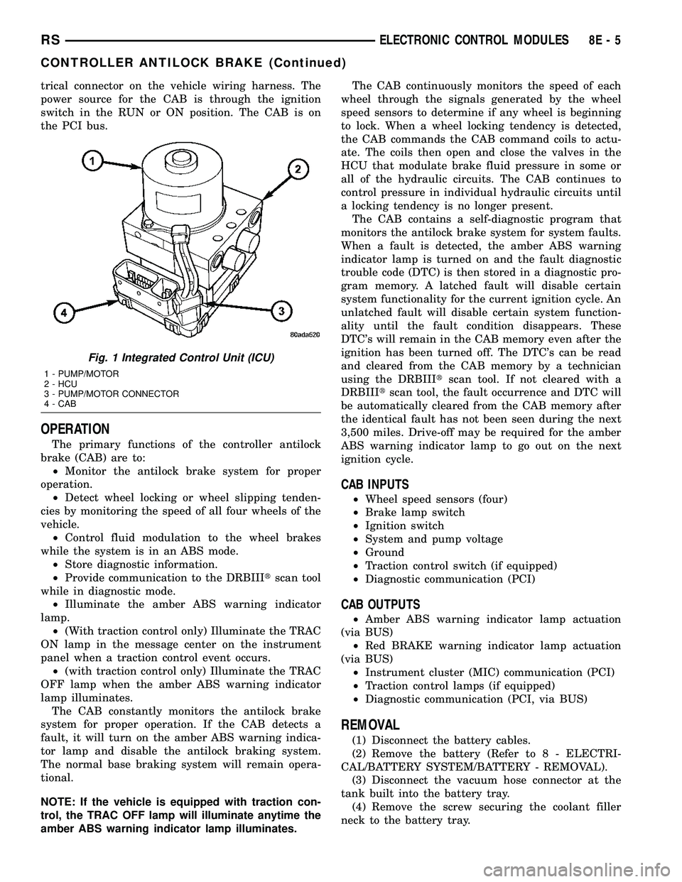
Fig. 1 Integrated Control Unit (ICU)
1 - PUMP/MOTOR
2 - HCU
3 - PUMP/MOTOR CONNECTOR
4 - CAB
RSELECTRONIC CONTROL MODULES8E-5
CONTROLLER ANTILOCK BRAKE (Continued)
Page 292 of 2339
FRONT CONTROL MODULE
DESCRIPTION
The Front Control Module (FCM) is a micro con-
troller based module located in the engine compart-
ment. The FCM mates to the Power Distribution
Center (PDC) to form the Integrated Power Module
(IPM). The IPM connects directly to the battery and
provides the primary means of circuit protection and
power distribution for all vehicle electrical systems.
The FCM controls power to some of these vehicle sys-
tems electrical and electromechanical loads based on
inputs received from hard wired switch inputs and
data received on the Programmable Communications
Interface (PCI) data bus.
For information on the IPM, (Refer to 8 - ELEC-
TRICAL/POWER DISTRIBUTION/INTEGRATED
POWER MODULE - DESCRIPTION)
OPERATION
As messages are sent over the Programmable Com-
munications Interface (PCI) data bus, the Front Con-
trol Module (FCM) reads these messages and controls
power to some of the vehicles electrical systems by
completing the circuit to ground (low side driver) or
completing the circuit to 12 volt power (high side
driver).
The following functions arecontrolledby the
Front Control Module:
²Accessory Relay Actuation
²Brake Transmission Shift Interlock Functions
(BTSI - gas engine only)
²Diesel Cabin Heater (Diesel Engine Vehicles)
²Electronic Back Light (EBL) Rear Defogger
²Front and Rear Blower Motor Relay Actuation
²Front Fog Lamp Relay Actuation
²Washer Motor (front and rear)
²Front Windshield Wiper ªHIº & ªLOº Relay
Actuation
²Front Windshield Wiper ªONº Relay Actuation
²Headlamp Power with Voltage Regulation
²Horn Relay Actuation
²Headlamp Washer Relay Actuation (IF
EQUIPPED - EXPORT ONLY)
²Name Brand Speaker (NBS) Relay Actuation
²Park Lamp Relay Actuation
The following inputs areReceived/Monitoredby
the Front Control Module:
²Ambient Temperature Sensing
²Back-Up switch
²Brake Fluid Level
²B+ Connection Detection
²Engine Crank Signal (Diesel Engine Vehicles)
²Horn Input
²Ignition Switch Start Only
²Ignition Switch Run and Start Only²Stop Lamp Sense
²Washer Fluid Level
²Windshield Wiper Park
DIAGNOSIS AND TESTING
FRONT CONTROL MODULE
The Front Control Module (FCM) is a printed cir-
cuit board based module with a on-board micro-pro-
cessor. The FCM interfaces with other electronic
modules in the vehicle via the Programmable Com-
munications Interface (PCI) data bus. In order to
obtain conclusive testing the PCI data bus and all of
the electronic modules that provide inputs to, or
receive outputs from the FCM must be checked. All
PCI communication faults must be resolved prior to
further diagnosing any front control module related
issues.
The FCM was designed to be diagnosed with an
appropriate diagnostic scan tool, such as the DRB
IIIt. The most reliable, efficient, and accurate means
to diagnose the front control module requires the use
of a DRB IIItscan tool and the proper Body Diag-
nostic Procedures manual.
Before any testing of the FCM is attempted, the
battery should be fully charged and all wire harness
and ground connections inspected around the affected
areas on the vehicle.
REMOVAL
(1) Disconnect and isolate the negative and posi-
tive battery cables from the battery.
(2) Remove the battery (Refer to 8 - ELECTRI-
CAL/BATTERY SYSTEM/BATTERY - REMOVAL).
(3) Using a long flat-bladed screwdriver, gently
twist the Integrated Power Module (IPM) retaining
clip outboard to free the IPM from its mounting
bracket (Fig. 5). Rotate IPM upward to access the
Front Control Module (FCM) retaining screws.
(4) Remove the front control module retaining
screws.
(5) Pull the FCM straight from the IPM assembly
to disconnect the electrical connector (Fig. 6) and
remove the FCM from the vehicle.
INSTALLATION
NOTE: Front Control Module must be programmed
to the correct radio EQ curve using the DRB IIIT.
This will ensure that the audio system is operating
correctly.
(1) Install the Front Control Module (FCM) in the
Integrated Power Module (IPM) assembly by pushing
the 49-way electrical connector straight in.
RSELECTRONIC CONTROL MODULES8E-7
Page 297 of 2339
²SCI Receive
²Speed Control
²Throttle Position Sensor
²Transmission Control Relay (Switched B+)
²Transmission Pressure Switches
²Transmission Temperature Sensor
²Transmission Input Shaft Speed Sensor
²Transmission Output Shaft Speed Sensor
²Transaxle Gear Engagement
²Vehicle Speed
NOTE: PCM Outputs:
²Air Conditioning Clutch Relay
²Automatic Shut Down (ASD) and Fuel Pump
Relays
²Data Link Connector (PCI and SCI Transmit)
²Double Start Override
²EGR Solenoid
²Fuel Injectors
²Generator Field
²High Speed Fan Relay
²Idle Air Control Motor
²Ignition Coils
²Leak Detection Pump
²Low Speed Fan Relay
²MTV Actuator
²Proportional Purge Solenoid
²SRV Valve
²Speed Control Relay
²Speed Control Vent Relay
²Speed Control Vacuum Relay
²8 Volt Output
²5 Volt Output
²Torque Reduction Request
²Transmission Control Relay
²Transmission Solenoids
²Vehicle Speed
Based on inputs it receives, the powertrain control
module (PCM) adjusts fuel injector pulse width, idle
speed, ignition timing, and canister purge operation.
The PCM regulates the cooling fans, air conditioning
and speed control systems. The PCM changes gener-
ator charge rate by adjusting the generator field.
The PCM adjusts injector pulse width (air-fuel
ratio) based on the following inputs.
²Battery Voltage
²Intake Air Temperature Sensor
²Engine Coolant Temperature
²Engine Speed (crankshaft position sensor)
²Exhaust Gas Oxygen Content (heated oxygen
sensors)
²Manifold Absolute Pressure
²Throttle Position
The PCM adjusts engine idle speed through the
idle air control motor based on the following inputs.
²Brake Switch²Engine Coolant Temperature
²Engine Speed (crankshaft position sensor)
²Park/Neutral
²Transaxle Gear Engagement
²Throttle Position
²Vehicle Speed
The PCM adjusts ignition timing based on the fol-
lowing inputs.
²Intake Air Temperature
²Engine Coolant Temperature
²Engine Speed (crankshaft position sensor)
²Knock Sensor
²Manifold Absolute Pressure
²Park/Neutral
²Transaxle Gear Engagement
²Throttle Position
The automatic shut down (ASD) and fuel pump
relays are mounted externally, but turned on and off
by the powertrain control module through the same
circuit.
The camshaft and crankshaft signals are sent to
the powertrain control module. If the PCM does not
receive both signals within approximately one second
of engine cranking, it deactivates the ASD and fuel
pump relays. When these relays are deactivated,
power is shut off to the fuel injectors, ignition coils,
fuel pump and the heating element in each oxygen
sensor.
The PCM contains a voltage converter that
changes battery voltage to a regulated 8.0 volts. The
8.0 volts power the camshaft position sensor, crank-
shaft position sensor and vehicle speed sensor. The
PCM also provides a 5.0 volts supply for the engine
coolant temperature sensor, intake air temperature
sensor, manifold absolute pressure sensor and throt-
tle position sensor.
The PCM engine control strategy prevents reduced
idle speeds until after the engine operates for 320 km
(200 miles). If the PCM is replaced after 320 km (200
miles) of usage, update the mileage in new PCM. Use
the DRBIIItscan tool to change the mileage in the
PCM. Refer to the appropriate Powertrain Diagnostic
Manual and the DRBIIItscan tool.
TRANSMISSION CONTROL
CLUTCH VOLUME INDEX (CVI)
An important function of the PCM is to monitor
Clutch Volume Index (CVI). CVIs represent the vol-
ume of fluid needed to compress a clutch pack.
The PCM monitors gear ratio changes by monitor-
ing the Input and Output Speed Sensors. The Input,
or Turbine Speed Sensor sends an electrical signal to
the PCM that represents input shaft rpm. The Out-
put Speed Sensor provides the PCM with output
shaft speed information.
8E - 12 ELECTRONIC CONTROL MODULESRS
POWERTRAIN CONTROL MODULE (Continued)
Page 374 of 2339
INSTRUMENT CLUSTER
TABLE OF CONTENTS
page page
INSTRUMENT CLUSTER
DESCRIPTION..........................1
OPERATION............................1
DIAGNOSIS AND TESTING
DIAGNOSIS AND TESTING - SELF-
DIAGNOSTICS.........................2
DIAGNOSIS AND TESTING - CLUSTER
DIAGNOSIS...........................3REMOVAL.............................11
INSTALLATION.........................11
CLUSTER LENS
REMOVAL.............................11
INSTALLATION.........................11
INSTRUMENT CLUSTER
DESCRIPTION
The instrumentation gauges are contained in a
subdial assembly within the instrument cluster. The
individual gauges are not serviceable. If one of the
cluster gauges becomes faulty, the entire cluster
would require replacement.
The Mechanical Instrument Cluster (MIC) with a
tachometer is equipped with a electronic vacuum flu-
orescent transmission range indicator (PRND3L),
odometer, and trip odometer display.
The MIC without a tachometer is equipped with a
Light Emitting Diode (LED) transmission range indi-
cator (PRND3L) and a vacuum fluorescent odometer
display.
The MIC is equipped with the following warning
lamps.
²Lift Gate Ajar
²Low Fuel Level
²Low Windshield Washer Fluid Level
²Cruise
²Battery Voltage
²Fasten Seat Belt
²Door Ajar
²Coolant Temperature
²Anti-Lock Brake
²Brake
²Oil Pressure
²MIL (Malfunction Indicator Lamp)
²VTSS/SKIS Indicator
²Airbag
²Traction Control
²Autostick
Export Only- uses a message center that displays
the following telltales:
²Turns Signals
²High Beam
²Tire Pressure Monitoring (TPM)²Glow Plug (Export Only)
²Supplemental Cabin Heater (Export Only)WATER IN FUEL LAMP - EXPORT
The Water In Fuel Lamp is located in the message
center. When moisture is found within the fuel sys-
tem, the sensor sends a message via the PCI data
bus to the instrument cluster. The MIC illuminates
the bulb in the message center, The sensor is located
underneath the vehicle, directly above the rear axle.
The sensor is housed within the fuel filter/water sep-
arator assembly cover. The sensor is not serviced sep-
arately. If found defective, the entire assembly cover
must be replaced.
OPERATION
Refer to the vehicle Owner's Manual for operation
instructions and conditions for the Instrument Clus-
ter Gauges.
WATER IN FUEL LAMP/SENSOR - EXPORT
The Water In Fuel Sensor is a resistive type
switch. It is calibrated to sense the different resis-
tance between diesel fuel and water. When water
enters the fuel system, it is caught in the bottom of
the fuel filter/water separator assembly, where the
sensor is located. Water has less resistance than die-
sel fuel. The sensor then sends a PCI data bus mes-
sage to the instrument cluster to illuminate the
lamp.
If the lamp is inoperative, perform the self diag-
nostic test on the instrument cluster to check the
lamp operation before continuing diagnosis.
RSINSTRUMENT CLUSTER8J-1
Page 405 of 2339
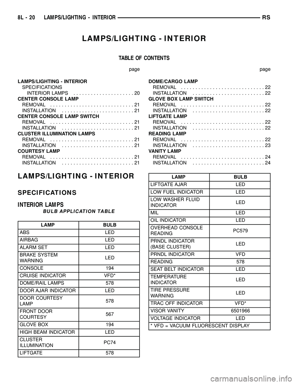
LAMPS/LIGHTING - INTERIOR
TABLE OF CONTENTS
page page
LAMPS/LIGHTING - INTERIOR
SPECIFICATIONS
INTERIOR LAMPS.....................20
CENTER CONSOLE LAMP
REMOVAL.............................21
INSTALLATION.........................21
CENTER CONSOLE LAMP SWITCH
REMOVAL.............................21
INSTALLATION.........................21
CLUSTER ILLUMINATION LAMPS
REMOVAL.............................21
INSTALLATION.........................21
COURTESY LAMP
REMOVAL.............................21
INSTALLATION.........................21DOME/CARGO LAMP
REMOVAL.............................22
INSTALLATION.........................22
GLOVE BOX LAMP SWITCH
REMOVAL.............................22
INSTALLATION.........................22
LIFTGATE LAMP
REMOVAL.............................22
INSTALLATION.........................22
READING LAMP
REMOVAL.............................22
INSTALLATION.........................23
VANITY LAMP
REMOVAL.............................24
INSTALLATION.........................24
LAMPS/LIGHTING - INTERIOR
SPECIFICATIONS
INTERIOR LAMPS
BULB APPLICATION TABLE
LAMP BULB
ABS LED
AIRBAG LED
ALARM SET LED
BRAKE SYSTEM
WARNINGLED
CONSOLE 194
CRUISE INDICATOR VFD*
DOME/RAIL LAMPS 578
DOOR AJAR INDICATOR LED
DOOR COURTESY
LAMP578
FRONT DOOR
COURTESY567
GLOVE BOX 194
HIGH BEAM INDICATOR LED
CLUSTER
ILLUMINATIONPC74
LIFTGATE 578
LAMP BULB
LIFTGATE AJAR LED
LOW FUEL INDICATOR LED
LOW WASHER FLUID
INDICATORLED
MIL LED
OIL INDICATOR LED
OVERHEAD CONSOLE
READINGPC579
PRNDL INDICATOR
(BASE CLUSTER)LED
PRNDL INDICATOR VFD
READING 578
SEAT BELT INDICATOR LED
TEMPERATURE
INDICATORLED
TIRE PRESSURE
WARNINGLED
TRAC OFF INDICATOR VFD*
VISOR VANITY 6501966
VOLTAGE INDICATOR LED
* VFD = VACUUM FLUORESCENT DISPLAY
8L - 20 LAMPS/LIGHTING - INTERIORRS
Page 582 of 2339
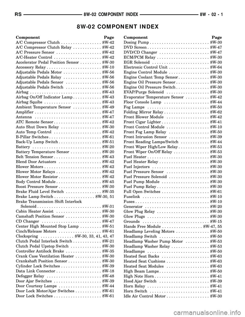
8W-02 COMPONENT INDEX
Component Page
A/C Compressor Clutch................. 8W-42
A/C Compressor Clutch Relay............ 8W-42
A/C Pressure Sensor................... 8W-42
A/C-Heater Control.................... 8W-42
Accelerator Pedal Position Sensor......... 8W-30
Accessory Relay....................... 8W-10
Adjustable Pedals Motor................ 8W-56
Adjustable Pedals Relay................ 8W-56
Adjustable Pedals Sensor............... 8W-56
Adjustable Pedals Switch............... 8W-56
Airbag.............................. 8W-43
Airbag On/Off Indicator Lamp............ 8W-43
Airbag Squibs........................ 8W-43
Ambient Temperature Sensor............ 8W-49
Amplifier............................ 8W-47
Antenna............................ 8W-47
ATC Remote Sensor.................... 8W-42
Auto Shut Down Relay................. 8W-30
Auto Temp Control.................... 8W-42
B-Pillar Switches...................... 8W-61
Back-Up Lamp Switch.................. 8W-51
Battery............................. 8W-20
Battery Temperature Sensor............. 8W-20
Belt Tension Sensor.................... 8W-43
Blend Door Actuators.................. 8W-42
Blower Motors........................ 8W-42
Blower Motor Relays................... 8W-42
Blower Motor Resistor.................. 8W-42
Body Control Module................... 8W-45
Boost Pressure Sensor.................. 8W-30
Brake Fluid Level Switch............... 8W-35
Brake Lamp Switch................. 8W-30, 51
Brake Transmission Shift Interlock
Solenoid........................... 8W-31
Cabin Heater Assist................... 8W-30
Camshaft Position Sensor............... 8W-30
CD Changer......................... 8W-47
Center High Mounted Stop Lamp......... 8W-51
Cinch/Release Motors.................. 8W-61
Clockspring.............. 8W-30, 33, 41, 43, 47
Clutch Pedal Interlock Switch............ 8W-21
Clutch Pedal Upstop Switch............. 8W-30
Controller Antilock Brake............... 8W-35
Crank Case Ventilation Heater........... 8W-30
Crankshaft Position Sensor.............. 8W-30
Cylinder Lock Switches................. 8W-39
Data Link Connector................... 8W-18
Defogger Relay....................... 8W-48
Door Ajar Switches.................... 8W-39
Door Courtesy Lamps.................. 8W-44
Door Lock Motor/Ajar Switches........... 8W-61
Door Lock Switches.................... 8W-61Component Page
Dosing Pump......................... 8W-30
DVD Screen.......................... 8W-47
DVD/CD Changer..................... 8W-47
ECM/PCM Relay...................... 8W-30
EGR Solenoid........................ 8W-30
Electronic Control Unit................. 8W-64
Engine Control Module................. 8W-30
Engine Coolant Temp Sensor............. 8W-30
Engine Oil Pressure Sensor.............. 8W-30
Engine Oil Pressure Switch.............. 8W-30
EVAP/Purge Solenoid.................. 8W-30
Evaporator Temperature Sensor.......... 8W-42
Floor Console Lamp................... 8W-44
Fog Lamps.......................... 8W-50
Folding Mirror Relay................... 8W-62
Front Blower Module.................. 8W-42
Front Cigar Lighter.................... 8W-41
Front Control Module.................. 8W-10
Front Fog Lamp Relay................. 8W-50
Front Intrusion Sensor................. 8W-39
Front Reading Lamps/Switch............ 8W-44
Front Wiper High/Low Relay............. 8W-53
Front Wiper On/Off Relay............... 8W-53
Fuel Heater.......................... 8W-30
Fuel Heater Relay..................... 8W-30
Fuel Injectors........................ 8W-30
Fuel Pressure Sensor.................. 8W-30
Fuel Pressure Solenoid................. 8W-30
Fuel Pump Module.................... 8W-30
Fuel Pump Relay...................... 8W-30
Full Open Switches.................... 8W-61
Fuselink............................ 8W-10
Fuses............................... 8W-10
Generator........................... 8W-20
Glow Plug Relay...................... 8W-30
Glow Plugs.......................... 8W-30
Grounds............................ 8W-15
Hands Free Module................. 8W-47, 55
Headlamp Leveling Motors.............. 8W-50
Headlamp Switch..................... 8W-50
Headlamp Washer Pump Motor.......... 8W-53
Headlamp Washer Relay................ 8W-53
Headlamps.......................... 8W-50
Heated Seat Backs.................... 8W-63
Heated Seat Cushions.................. 8W-63
Heated Seat Modules.................. 8W-63
High Beam Lamps..................... 8W-50
High Note Horn....................... 8W-41
Hood Ajar Switch..................... 8W-39
Horn Relay.......................... 8W-41
Horn Switch......................... 8W-41
Idle Air Control Motor.................. 8W-30
RS8W-02 COMPONENT INDEX8W-02-1
Page 583 of 2339
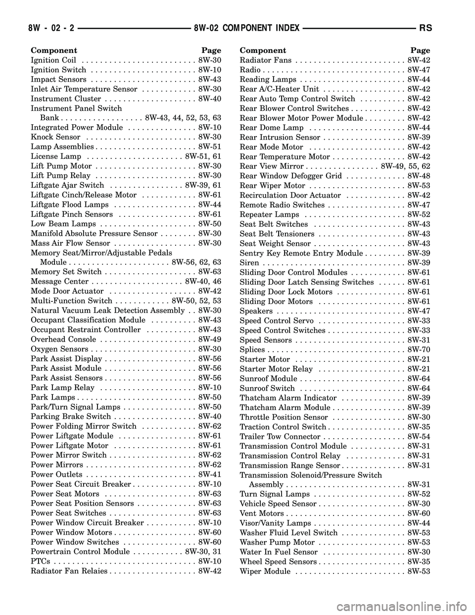
Component Page
Ignition Coil......................... 8W-30
Ignition Switch....................... 8W-10
Impact Sensors....................... 8W-43
Inlet Air Temperature Sensor............ 8W-30
Instrument Cluster.................... 8W-40
Instrument Panel Switch
Bank.................. 8W-43, 44, 52, 53, 63
Integrated Power Module............... 8W-10
Knock Sensor........................ 8W-30
Lamp Assemblies...................... 8W-51
License Lamp..................... 8W-51, 61
Lift Pump Motor...................... 8W-30
Lift Pump Relay...................... 8W-30
Liftgate Ajar Switch................ 8W-39, 61
Liftgate Cinch/Release Motor............ 8W-61
Liftgate Flood Lamps.................. 8W-44
Liftgate Pinch Sensors................. 8W-61
Low Beam Lamps..................... 8W-50
Manifold Absolute Pressure Sensor........ 8W-30
Mass Air Flow Sensor.................. 8W-30
Memory Seat/Mirror/Adjustable Pedals
Module...................... 8W-56, 62, 63
Memory Set Switch.................... 8W-63
Message Center.................... 8W-40, 46
Mode Door Actuator................... 8W-42
Multi-Function Switch............ 8W-50, 52, 53
Natural Vacuum Leak Detection Assembly . . 8W-30
Occupant Classification Module.......... 8W-43
Occupant Restraint Controller........... 8W-43
Overhead Console..................... 8W-49
Oxygen Sensors....................... 8W-30
Park Assist Display.................... 8W-56
Park Assist Module.................... 8W-56
Park Assist Sensors.................... 8W-56
Park Lamp Relay..................... 8W-10
Park Lamps.......................... 8W-50
Park/Turn Signal Lamps................ 8W-50
Parking Brake Switch.................. 8W-40
Power Folding Mirror Switch............ 8W-62
Power Liftgate Module................. 8W-61
Power Liftgate Motor.................. 8W-61
Power Mirror Switch................... 8W-62
Power Mirrors........................ 8W-62
Power Outlets........................ 8W-41
Power Seat Circuit Breaker.............. 8W-10
Power Seat Motors.................... 8W-63
Power Seat Position Sensors............. 8W-63
Power Seat Switches................... 8W-63
Power Window Circuit Breaker........... 8W-10
Power Window Motors.................. 8W-60
Power Window Switches................ 8W-60
Powertrain Control Module........... 8W-30, 31
PTCs............................... 8W-10
Radiator Fan Relaies................... 8W-42Component Page
Radiator Fans........................ 8W-42
Radio............................... 8W-47
Reading Lamps....................... 8W-44
Rear A/C-Heater Unit.................. 8W-42
Rear Auto Temp Control Switch.......... 8W-42
Rear Blower Control Switches............ 8W-42
Rear Blower Motor Power Module......... 8W-42
Rear Dome Lamp..................... 8W-44
Rear Intrusion Sensor.................. 8W-39
Rear Mode Motor..................... 8W-42
Rear Temperature Motor................ 8W-42
Rear View Mirror................ 8W-49, 55, 62
Rear Window Defogger Grid............. 8W-48
Rear Wiper Motor..................... 8W-53
Recirculation Door Actuator............. 8W-42
Remote Radio Switches................. 8W-47
Repeater Lamps...................... 8W-52
Seat Belt Switches.................... 8W-43
Seat Belt Tensioners................... 8W-43
Seat Weight Sensor.................... 8W-43
Sentry Key Remote Entry Module......... 8W-39
Siren............................... 8W-39
Sliding Door Control Modules............ 8W-61
Sliding Door Latch Sensing Switches...... 8W-61
Sliding Door Lock Motors............... 8W-61
Sliding Door Motors................... 8W-61
Speakers............................ 8W-47
Speed Control Servo................... 8W-33
Speed Control Switches................. 8W-33
Speed Sensors........................ 8W-31
Splices.............................. 8W-70
Starter Motor........................ 8W-21
Starter Motor Relay................... 8W-21
Sunroof Module....................... 8W-64
Sunroof Switch....................... 8W-64
Thatcham Alarm Indicator.............. 8W-39
Thatcham Alarm Module................ 8W-39
Throttle Position Sensor................ 8W-30
Traction Control Switch................. 8W-35
Trailer Tow Connector.................. 8W-54
Transmission Control Module............ 8W-31
Transmission Control Relay............. 8W-31
Transmission Range Sensor.............. 8W-31
Transmission Solenoid/Pressure Switch
Assembly.......................... 8W-31
Turn Signal Lamps.................... 8W-52
Vehicle Speed Sensor................... 8W-30
Vent Motors.......................... 8W-60
Visor/Vanity Lamps.................... 8W-44
Washer Fluid Level Switch.............. 8W-53
Washer Pump Motor................... 8W-53
Water In Fuel Sensor.................. 8W-30
Wheel Speed Sensors................... 8W-35
Wiper Module........................ 8W-53
8W - 02 - 2 8W-02 COMPONENT INDEXRS