brake light CHRYSLER CARAVAN 2005 Service Manual
[x] Cancel search | Manufacturer: CHRYSLER, Model Year: 2005, Model line: CARAVAN, Model: CHRYSLER CARAVAN 2005Pages: 2339, PDF Size: 59.69 MB
Page 6 of 2339
FASTENER USAGE
DESCRIPTION
FASTENER USAGE
WARNING: USE OF AN INCORRECT FASTENER
MAY RESULT IN COMPONENT DAMAGE OR PER-
SONAL INJURY.
Fasteners and torque specifications references in
this Service Manual are identified in metric and SAE
format.
During any maintenance or repair procedures, it is
important to salvage all fasteners (nuts, bolts, etc.)
for reassembly. If the fastener is not salvageable, a
fastener of equivalent specification must be used.
THREADED HOLE REPAIR
Most stripped threaded holes can be repaired using
a Helicoilt. Follow the vehicle or Helicoiltrecommen-
dations for application and repair procedures.
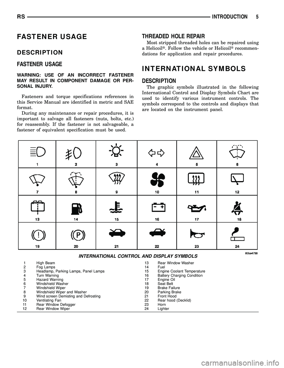
INTERNATIONAL SYMBOLS
DESCRIPTION
The graphic symbols illustrated in the following
International Control and Display Symbols Chart are
used to identify various instrument controls. The
symbols correspond to the controls and displays that
are located on the instrument panel.
INTERNATIONAL CONTROL AND DISPLAY SYMBOLS
1 High Beam 13 Rear Window Washer
2 Fog Lamps 14 Fuel
3 Headlamp, Parking Lamps, Panel Lamps 15 Engine Coolant Temperature
4 Turn Warning 16 Battery Charging Condition
5 Hazard Warning 17 Engine Oil
6 Windshield Washer 18 Seat Belt
7 Windshield Wiper 19 Brake Failure
8 Windshield Wiper and Washer 20 Parking Brake
9 Wind screen Demisting and Defrosting 21 Front Hood
10 Ventilating Fan 22 Rear hood (Decklid)
11 Rear Window Defogger 23 Horn
12 Rear Window Wiper 24 Lighter
RSINTRODUCTION5
Page 20 of 2339
FLUID FILL/CHECK
LOCATIONS
DESCRIPTION
The fluid check/fill point locations are located in
each applicable service manual section.
LUBRICATION POINTS
DESCRIPTION
Lubrication point locations are located in each
applicable Sections.
MAINTENANCE SCHEDULES
DESCRIPTION
DESCRIPTION
There are two maintenance schedules that show
therequiredservice for your vehicle.
First is ScheduleªBº. It is for vehicles that are
operated under the conditions that are listed below
and at the beginning of the schedule.
²Day or night temperatures are below 32É F (0É
C).
²Stop and go driving.
²Extensive engine idling.
²Driving in dusty conditions.
²Short trips of less than 10 miles (16 km).
²More than 50% of your driving is at sustained
high speeds during hot weather, above 90É F (32É C).
²Trailer towing.L
²Taxi, police, or delivery service (commercial ser-
vice).L
²Off-road or desert operation.
NOTE: Most vehicles are operated under the condi-
tions listed for Schedule(B(.
Second is ScheduleªAº. It is for vehicles that are
not operated under any of the conditions listed under
Schedule9B9.
Use the schedule that best describes your driving
conditions. Where time and mileage are listed, follow
the interval that occurs first.
CAUTION: Failure to perform the required mainte-
nance items may result in damage to the vehicle.
At Each Stop for Fuel
²Check the engine oil level about 5 minutes after
a fully warmed engine is shut off. Checking the oil
level while the vehicle is on level ground will
improve the accuracy of the oil level reading. Add oil
only when the level is at or below the ADD or MIN
mark.
²Check the windshield washer solvent and add if
required.
Once a Month
²Check tire pressure and look for unusual wear
or damage.
²Inspect the battery and clean and tighten the
terminals as required.
²Check the fluid levels of coolant reservoir, brake
master cylinder and transmission, add as needed.
²Check all lights and all other electrical items for
correct operation.
At Each Oil Change
²Change the engine oil filter.
²Inspect the exhaust system.
²Inspect the brake hoses.
²Inspect the CV joints and front suspension com-
ponents.
²Check the automatic transmission fluid level.
²Check the coolant level, hoses, and clamps.
SCHEDULE B
Follow schedule ªBº if you usually operate your
vehicle under one or more of the following conditions.
Change the automatic transmission fluid and filter
every 60,000 miles (96 000 km) if the vehicle is usu-
ally operated under one or more of the conditions
marked with anL.
²Day or night temperatures are below 32É F (0É
C).
²Stop and go driving.
²Extensive engine idling.
²Driving in dusty conditions.
²Short trips of less than 10 miles (16 km).
²More than 50% of your driving is at sustained
high speeds during hot weather, above 90É F (32É C).
²Trailer towing.L
²Taxi, police, or delivery service (commercial ser-
vice).L
²Off-road or desert operation.
RSLUBRICATION & MAINTENANCE0-7
Page 26 of 2339
DESCRIPTION - EXPORT
There are two maintenance schedules that show
therequiredservice for your vehicle.
First is ScheduleªAº. It is for vehicles that are not
operated under any of the conditions listed under
Schedule9B9.
Second is ScheduleªBº. It is for vehicles that are
operated under the conditions that are listed below
and at the beginning of the schedule.
²Day or night temperatures are below 0É C (32É
F).
²Stop and go driving.
²Extensive engine idling.
²Driving in dusty conditions.
²Short trips of less than 16 km (10 miles).
²More than 50% of your driving is at sustained
high speeds during hot weather, above 32É C (90É F).
²Trailer towing.L
²Taxi, police, or delivery service (commercial ser-
vice).L
²Off-road or desert operation.
NOTE: Most vehicles are operated under the condi-
tions listed for Schedule(B(.
Use the schedule that best describes your driving
conditions. Where time and mileage are listed, follow
the interval that occurs first.
CAUTION: Failure to perform the required mainte-
nance items may result in damage to the vehicle.
At Each Stop for Fuel
²Check the engine oil level about 5 minutes after
a fully warmed engine is shut off. Checking the oil
level while the vehicle is on level ground will
improve the accuracy of the oil level reading. Add oil
only when the level is at or below the ADD or MIN
mark.
²Check the windshield washer solvent and add if
required.
Once a Month
²Check tire pressure and look for unusual wear
or damage.
²Inspect the battery and clean and tighten the
terminals as required.
²Check the fluid levels of coolant reservoir, brake
master cylinder and transmission, add as needed.
²Check all lights and all other electrical items for
correct operation.
At Each Oil Change
²Change the engine oil filter.
²Inspect the exhaust system.
²Inspect the brake hoses.
²Inspect the CV joints and front suspension com-
ponents.
²Check the automatic transmission fluid level.
²Check the manual transmission fluid level.
²Check the coolant level, hoses, and clamps.
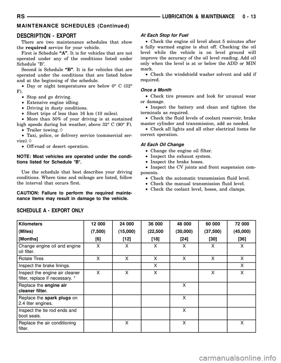
SCHEDULE A - EXPORT ONLY
Kilometers 12 000 24 000 36 000 48 000 60 000 72 000
(Miles) (7,500) (15,000) (22,500 (30,000) (37,500) (45,000)
[Months] [6] [12] [18] [24] [30] [36]
Change engine oil and engine
oil filter.XXXXX X
Rotate Tires XXXXX X
Inspect the brake linings. X X
Inspect the engine air cleaner
filter, replace if necessary. *XXX X X
Replace theengine air
cleaner filter.X
Replace thespark plugson
2.4 liter engines.X
Inspect the tie rod ends and
boot seals.X
Replace the air conditioning
filter.XX X
RSLUBRICATION & MAINTENANCE0-13
MAINTENANCE SCHEDULES (Continued)
Page 34 of 2339
Kilometers 173 000 178 000 182 000 187 000 192 000
(Miles) (108,000) (111,000) (114,000) (117,000) (120,000)
Inspect the generator belt on 2.4 liter
engines, replace if necessary.X
Inspect engine accessory drive belts on 3.3
liter engines, replace if necessary. ³X
Inspect the tie rod ends and boot seals. X
Inspect thePCV valveand replace as
necessary.*X
Change the automatic transmission fluid
and filter.LX
Change the All Wheel Drive (AWD) power
transfer unit fluid. (See note at the end of
this chart)X
Replace the air conditioning filter.X
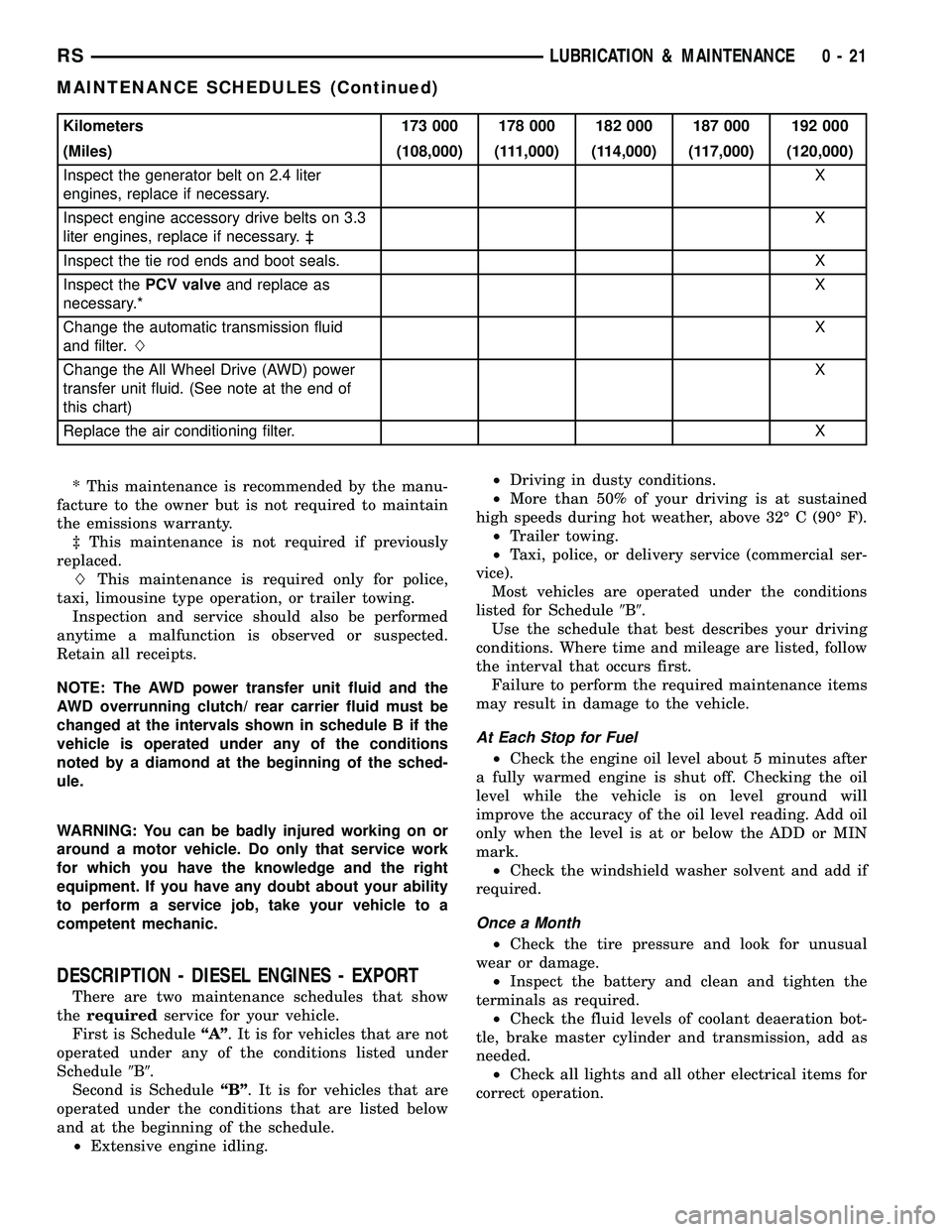
* This maintenance is recommended by the manu-
facture to the owner but is not required to maintain
the emissions warranty.
³ This maintenance is not required if previously
replaced.
LThis maintenance is required only for police,
taxi, limousine type operation, or trailer towing.
Inspection and service should also be performed
anytime a malfunction is observed or suspected.
Retain all receipts.
NOTE: The AWD power transfer unit fluid and the
AWD overrunning clutch/ rear carrier fluid must be
changed at the intervals shown in schedule B if the
vehicle is operated under any of the conditions
noted by a diamond at the beginning of the sched-
ule.
WARNING: You can be badly injured working on or
around a motor vehicle. Do only that service work
for which you have the knowledge and the right
equipment. If you have any doubt about your ability
to perform a service job, take your vehicle to a
competent mechanic.
DESCRIPTION - DIESEL ENGINES - EXPORT
There are two maintenance schedules that show
therequiredservice for your vehicle.
First is ScheduleªAº. It is for vehicles that are not
operated under any of the conditions listed under
Schedule9B9.
Second is ScheduleªBº. It is for vehicles that are
operated under the conditions that are listed below
and at the beginning of the schedule.
²Extensive engine idling.²Driving in dusty conditions.
²More than 50% of your driving is at sustained
high speeds during hot weather, above 32É C (90É F).
²Trailer towing.
²Taxi, police, or delivery service (commercial ser-
vice).
Most vehicles are operated under the conditions
listed for Schedule9B9.
Use the schedule that best describes your driving
conditions. Where time and mileage are listed, follow
the interval that occurs first.
Failure to perform the required maintenance items
may result in damage to the vehicle.
At Each Stop for Fuel
²Check the engine oil level about 5 minutes after
a fully warmed engine is shut off. Checking the oil
level while the vehicle is on level ground will
improve the accuracy of the oil level reading. Add oil
only when the level is at or below the ADD or MIN
mark.
²Check the windshield washer solvent and add if
required.
Once a Month
²Check the tire pressure and look for unusual
wear or damage.
²Inspect the battery and clean and tighten the
terminals as required.
²Check the fluid levels of coolant deaeration bot-
tle, brake master cylinder and transmission, add as
needed.
²Check all lights and all other electrical items for
correct operation.
RSLUBRICATION & MAINTENANCE0-21
MAINTENANCE SCHEDULES (Continued)
Page 46 of 2339
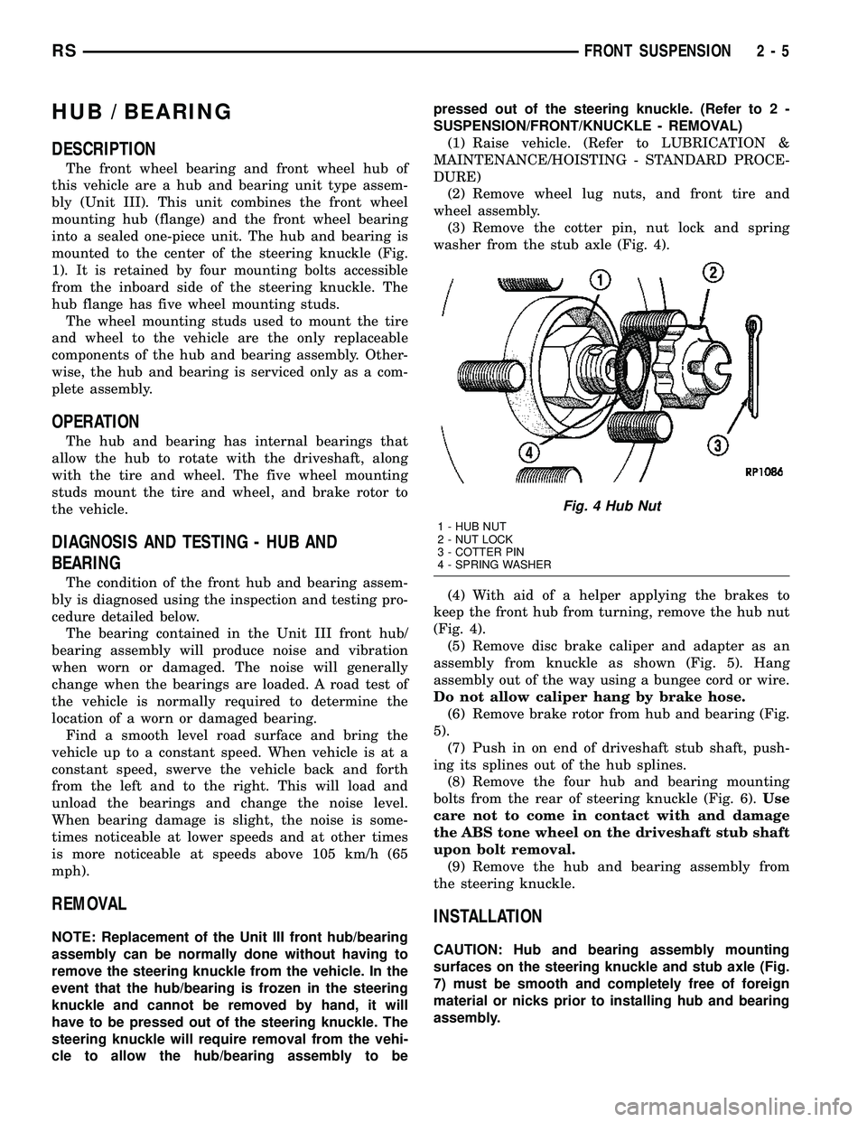
HUB / BEARING
DESCRIPTION
The front wheel bearing and front wheel hub of
this vehicle are a hub and bearing unit type assem-
bly (Unit III). This unit combines the front wheel
mounting hub (flange) and the front wheel bearing
into a sealed one-piece unit. The hub and bearing is
mounted to the center of the steering knuckle (Fig.
1). It is retained by four mounting bolts accessible
from the inboard side of the steering knuckle. The
hub flange has five wheel mounting studs.
The wheel mounting studs used to mount the tire
and wheel to the vehicle are the only replaceable
components of the hub and bearing assembly. Other-
wise, the hub and bearing is serviced only as a com-
plete assembly.
OPERATION
The hub and bearing has internal bearings that
allow the hub to rotate with the driveshaft, along
with the tire and wheel. The five wheel mounting
studs mount the tire and wheel, and brake rotor to
the vehicle.
DIAGNOSIS AND TESTING - HUB AND
BEARING
The condition of the front hub and bearing assem-
bly is diagnosed using the inspection and testing pro-
cedure detailed below.
The bearing contained in the Unit III front hub/
bearing assembly will produce noise and vibration
when worn or damaged. The noise will generally
change when the bearings are loaded. A road test of
the vehicle is normally required to determine the
location of a worn or damaged bearing.
Find a smooth level road surface and bring the
vehicle up to a constant speed. When vehicle is at a
constant speed, swerve the vehicle back and forth
from the left and to the right. This will load and
unload the bearings and change the noise level.
When bearing damage is slight, the noise is some-
times noticeable at lower speeds and at other times
is more noticeable at speeds above 105 km/h (65
mph).
REMOVAL
NOTE: Replacement of the Unit III front hub/bearing
assembly can be normally done without having to
remove the steering knuckle from the vehicle. In the
event that the hub/bearing is frozen in the steering
knuckle and cannot be removed by hand, it will
have to be pressed out of the steering knuckle. The
steering knuckle will require removal from the vehi-
cle to allow the hub/bearing assembly to bepressed out of the steering knuckle. (Refer to 2 -
SUSPENSION/FRONT/KNUCKLE - REMOVAL)
(1) Raise vehicle. (Refer to LUBRICATION &
MAINTENANCE/HOISTING - STANDARD PROCE-
DURE)
(2) Remove wheel lug nuts, and front tire and
wheel assembly.
(3) Remove the cotter pin, nut lock and spring
washer from the stub axle (Fig. 4).
(4) With aid of a helper applying the brakes to
keep the front hub from turning, remove the hub nut
(Fig. 4).
(5) Remove disc brake caliper and adapter as an
assembly from knuckle as shown (Fig. 5). Hang
assembly out of the way using a bungee cord or wire.
Do not allow caliper hang by brake hose.
(6) Remove brake rotor from hub and bearing (Fig.
5).
(7) Push in on end of driveshaft stub shaft, push-
ing its splines out of the hub splines.
(8) Remove the four hub and bearing mounting
bolts from the rear of steering knuckle (Fig. 6).Use
care not to come in contact with and damage
the ABS tone wheel on the driveshaft stub shaft
upon bolt removal.
(9) Remove the hub and bearing assembly from
the steering knuckle.
INSTALLATION
CAUTION: Hub and bearing assembly mounting
surfaces on the steering knuckle and stub axle (Fig.
7) must be smooth and completely free of foreign
material or nicks prior to installing hub and bearing
assembly.
Fig. 4 Hub Nut
1 - HUB NUT
2 - NUT LOCK
3 - COTTER PIN
4 - SPRING WASHER
RSFRONT SUSPENSION2-5
Page 71 of 2339
(9) Tighten nut (Fig. 5), removing bushing from
spring eye.
(10) Remove the tool from spring, then remove
bushing from tool.
INSTALLATION
(1) Install by hand NEW bushing in left side of
leaf spring eye.
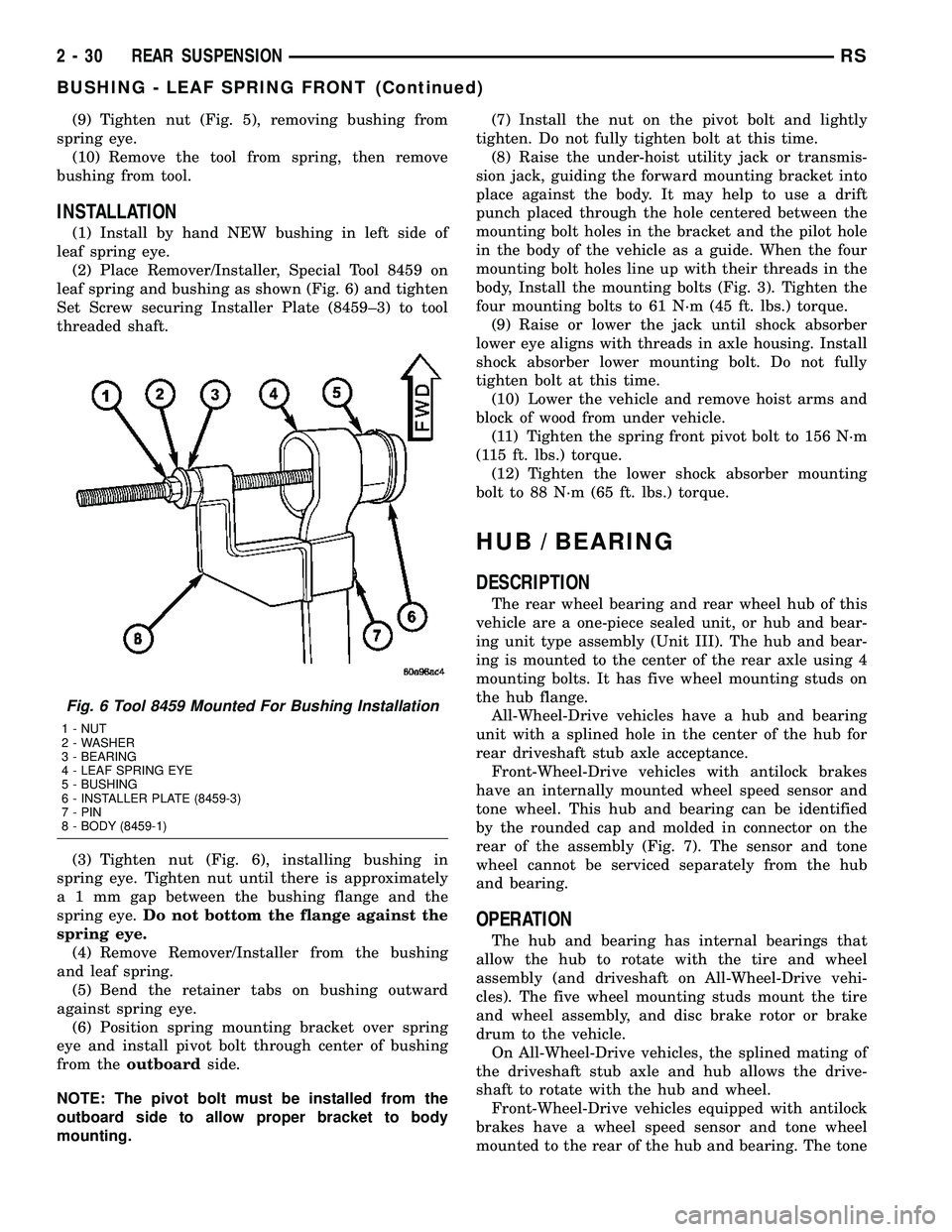
(2) Place Remover/Installer, Special Tool 8459 on
leaf spring and bushing as shown (Fig. 6) and tighten
Set Screw securing Installer Plate (8459±3) to tool
threaded shaft.
(3) Tighten nut (Fig. 6), installing bushing in
spring eye. Tighten nut until there is approximately
a 1 mm gap between the bushing flange and the
spring eye.Do not bottom the flange against the
spring eye.
(4) Remove Remover/Installer from the bushing
and leaf spring.
(5) Bend the retainer tabs on bushing outward
against spring eye.
(6) Position spring mounting bracket over spring
eye and install pivot bolt through center of bushing
from theoutboardside.
NOTE: The pivot bolt must be installed from the
outboard side to allow proper bracket to body
mounting.(7) Install the nut on the pivot bolt and lightly
tighten. Do not fully tighten bolt at this time.
(8) Raise the under-hoist utility jack or transmis-
sion jack, guiding the forward mounting bracket into
place against the body. It may help to use a drift
punch placed through the hole centered between the
mounting bolt holes in the bracket and the pilot hole
in the body of the vehicle as a guide. When the four
mounting bolt holes line up with their threads in the
body, Install the mounting bolts (Fig. 3). Tighten the
four mounting bolts to 61 N´m (45 ft. lbs.) torque.
(9) Raise or lower the jack until shock absorber
lower eye aligns with threads in axle housing. Install
shock absorber lower mounting bolt. Do not fully
tighten bolt at this time.
(10) Lower the vehicle and remove hoist arms and
block of wood from under vehicle.
(11) Tighten the spring front pivot bolt to 156 N´m
(115 ft. lbs.) torque.
(12) Tighten the lower shock absorber mounting
bolt to 88 N´m (65 ft. lbs.) torque.
HUB / BEARING
DESCRIPTION
The rear wheel bearing and rear wheel hub of this
vehicle are a one-piece sealed unit, or hub and bear-
ing unit type assembly (Unit III). The hub and bear-
ing is mounted to the center of the rear axle using 4
mounting bolts. It has five wheel mounting studs on
the hub flange.
All-Wheel-Drive vehicles have a hub and bearing
unit with a splined hole in the center of the hub for
rear driveshaft stub axle acceptance.
Front-Wheel-Drive vehicles with antilock brakes
have an internally mounted wheel speed sensor and
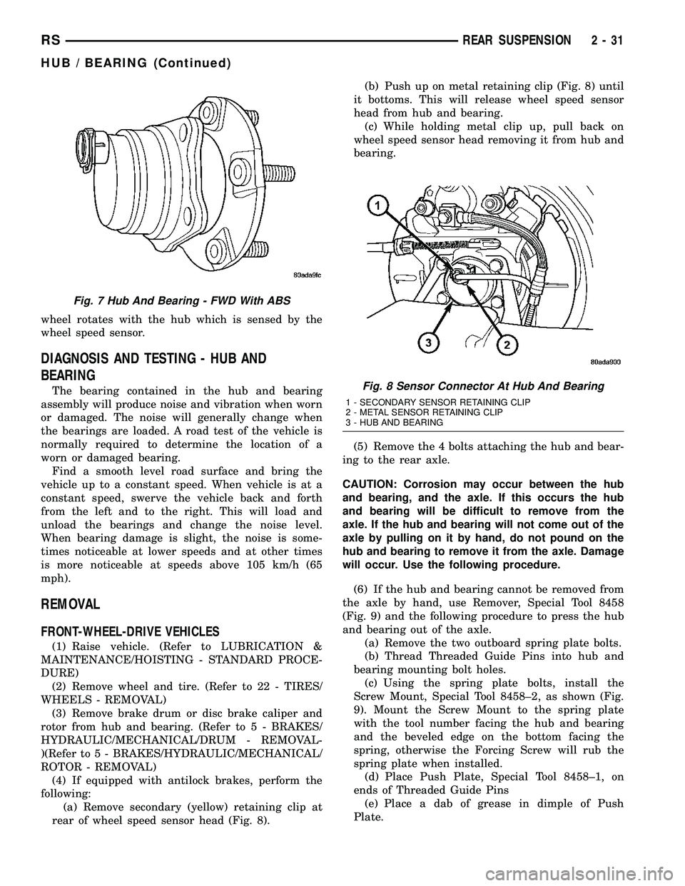
tone wheel. This hub and bearing can be identified
by the rounded cap and molded in connector on the
rear of the assembly (Fig. 7). The sensor and tone
wheel cannot be serviced separately from the hub
and bearing.
OPERATION
The hub and bearing has internal bearings that
allow the hub to rotate with the tire and wheel
assembly (and driveshaft on All-Wheel-Drive vehi-
cles). The five wheel mounting studs mount the tire
and wheel assembly, and disc brake rotor or brake
drum to the vehicle.
On All-Wheel-Drive vehicles, the splined mating of
the driveshaft stub axle and hub allows the drive-
shaft to rotate with the hub and wheel.
Front-Wheel-Drive vehicles equipped with antilock
brakes have a wheel speed sensor and tone wheel
mounted to the rear of the hub and bearing. The tone
Fig. 6 Tool 8459 Mounted For Bushing Installation
1 - NUT
2 - WASHER
3 - BEARING
4 - LEAF SPRING EYE
5 - BUSHING
6 - INSTALLER PLATE (8459-3)
7 - PIN
8 - BODY (8459-1)
2 - 30 REAR SUSPENSIONRS
BUSHING - LEAF SPRING FRONT (Continued)
Page 72 of 2339
wheel rotates with the hub which is sensed by the
wheel speed sensor.
DIAGNOSIS AND TESTING - HUB AND
BEARING
The bearing contained in the hub and bearing
assembly will produce noise and vibration when worn
or damaged. The noise will generally change when
the bearings are loaded. A road test of the vehicle is
normally required to determine the location of a
worn or damaged bearing.
Find a smooth level road surface and bring the
vehicle up to a constant speed. When vehicle is at a
constant speed, swerve the vehicle back and forth
from the left and to the right. This will load and
unload the bearings and change the noise level.
When bearing damage is slight, the noise is some-
times noticeable at lower speeds and at other times
is more noticeable at speeds above 105 km/h (65
mph).
REMOVAL
FRONT-WHEEL-DRIVE VEHICLES
(1) Raise vehicle. (Refer to LUBRICATION &
MAINTENANCE/HOISTING - STANDARD PROCE-
DURE)
(2) Remove wheel and tire. (Refer to 22 - TIRES/
WHEELS - REMOVAL)
(3) Remove brake drum or disc brake caliper and
rotor from hub and bearing. (Refer to 5 - BRAKES/
HYDRAULIC/MECHANICAL/DRUM - REMOVAL-
)(Refer to 5 - BRAKES/HYDRAULIC/MECHANICAL/
ROTOR - REMOVAL)
(4) If equipped with antilock brakes, perform the
following:
(a) Remove secondary (yellow) retaining clip at
rear of wheel speed sensor head (Fig. 8).(b) Push up on metal retaining clip (Fig. 8) until
it bottoms. This will release wheel speed sensor
head from hub and bearing.
(c) While holding metal clip up, pull back on
wheel speed sensor head removing it from hub and
bearing.
(5) Remove the 4 bolts attaching the hub and bear-
ing to the rear axle.
CAUTION: Corrosion may occur between the hub
and bearing, and the axle. If this occurs the hub
and bearing will be difficult to remove from the
axle. If the hub and bearing will not come out of the
axle by pulling on it by hand, do not pound on the
hub and bearing to remove it from the axle. Damage
will occur. Use the following procedure.
(6) If the hub and bearing cannot be removed from
the axle by hand, use Remover, Special Tool 8458
(Fig. 9) and the following procedure to press the hub
and bearing out of the axle.
(a) Remove the two outboard spring plate bolts.
(b) Thread Threaded Guide Pins into hub and
bearing mounting bolt holes.
(c) Using the spring plate bolts, install the
Screw Mount, Special Tool 8458±2, as shown (Fig.
9). Mount the Screw Mount to the spring plate
with the tool number facing the hub and bearing
and the beveled edge on the bottom facing the
spring, otherwise the Forcing Screw will rub the
spring plate when installed.
(d) Place Push Plate, Special Tool 8458±1, on
ends of Threaded Guide Pins
(e) Place a dab of grease in dimple of Push
Plate.
Fig. 7 Hub And Bearing - FWD With ABS
Fig. 8 Sensor Connector At Hub And Bearing
1 - SECONDARY SENSOR RETAINING CLIP
2 - METAL SENSOR RETAINING CLIP
3 - HUB AND BEARING
RSREAR SUSPENSION2-31
HUB / BEARING (Continued)
Page 73 of 2339
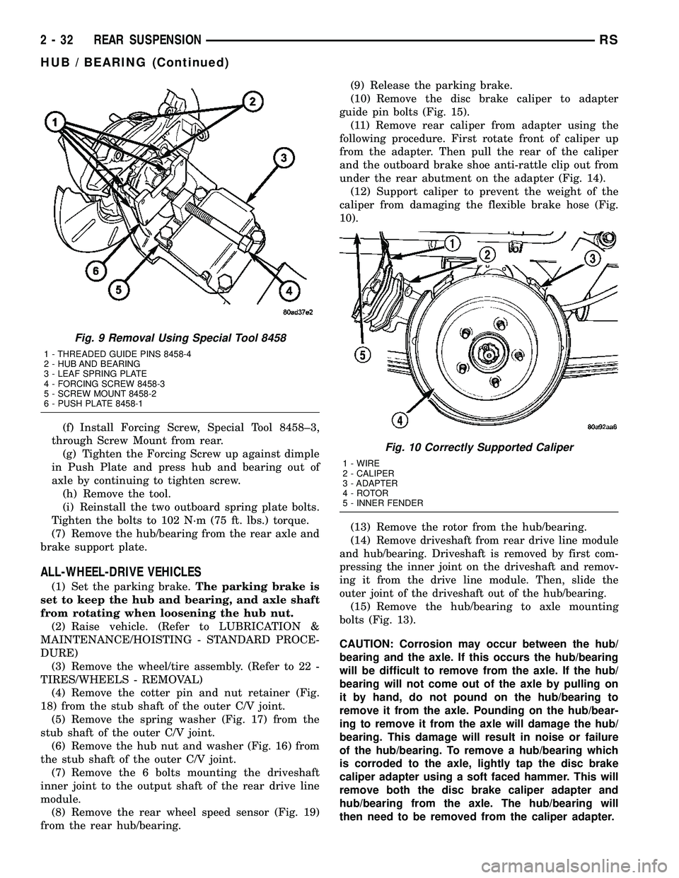
(f) Install Forcing Screw, Special Tool 8458±3,
through Screw Mount from rear.
(g) Tighten the Forcing Screw up against dimple
in Push Plate and press hub and bearing out of
axle by continuing to tighten screw.
(h) Remove the tool.
(i) Reinstall the two outboard spring plate bolts.
Tighten the bolts to 102 N´m (75 ft. lbs.) torque.
(7) Remove the hub/bearing from the rear axle and
brake support plate.
ALL-WHEEL-DRIVE VEHICLES
(1) Set the parking brake.The parking brake is
set to keep the hub and bearing, and axle shaft
from rotating when loosening the hub nut.
(2) Raise vehicle. (Refer to LUBRICATION &
MAINTENANCE/HOISTING - STANDARD PROCE-
DURE)
(3) Remove the wheel/tire assembly. (Refer to 22 -
TIRES/WHEELS - REMOVAL)
(4) Remove the cotter pin and nut retainer (Fig.
18) from the stub shaft of the outer C/V joint.
(5) Remove the spring washer (Fig. 17) from the
stub shaft of the outer C/V joint.
(6) Remove the hub nut and washer (Fig. 16) from
the stub shaft of the outer C/V joint.
(7) Remove the 6 bolts mounting the driveshaft
inner joint to the output shaft of the rear drive line
module.
(8) Remove the rear wheel speed sensor (Fig. 19)
from the rear hub/bearing.(9) Release the parking brake.
(10) Remove the disc brake caliper to adapter
guide pin bolts (Fig. 15).
(11) Remove rear caliper from adapter using the
following procedure. First rotate front of caliper up
from the adapter. Then pull the rear of the caliper
and the outboard brake shoe anti-rattle clip out from
under the rear abutment on the adapter (Fig. 14).
(12) Support caliper to prevent the weight of the
caliper from damaging the flexible brake hose (Fig.
10).
(13) Remove the rotor from the hub/bearing.
(14)
Remove driveshaft from rear drive line module
and hub/bearing. Driveshaft is removed by first com-
pressing the inner joint on the driveshaft and remov-
ing it from the drive line module. Then, slide the
outer joint of the driveshaft out of the hub/bearing.
(15) Remove the hub/bearing to axle mounting
bolts (Fig. 13).
CAUTION: Corrosion may occur between the hub/
bearing and the axle. If this occurs the hub/bearing
will be difficult to remove from the axle. If the hub/
bearing will not come out of the axle by pulling on
it by hand, do not pound on the hub/bearing to
remove it from the axle. Pounding on the hub/bear-
ing to remove it from the axle will damage the hub/
bearing. This damage will result in noise or failure
of the hub/bearing. To remove a hub/bearing which
is corroded to the axle, lightly tap the disc brake
caliper adapter using a soft faced hammer. This will
remove both the disc brake caliper adapter and
hub/bearing from the axle. The hub/bearing will
then need to be removed from the caliper adapter.
Fig. 9 Removal Using Special Tool 8458
1 - THREADED GUIDE PINS 8458-4
2 - HUB AND BEARING
3 - LEAF SPRING PLATE
4 - FORCING SCREW 8458-3
5 - SCREW MOUNT 8458-2
6 - PUSH PLATE 8458-1
Fig. 10 Correctly Supported Caliper
1 - WIRE
2 - CALIPER
3 - ADAPTER
4 - ROTOR
5 - INNER FENDER
2 - 32 REAR SUSPENSIONRS
HUB / BEARING (Continued)
Page 74 of 2339
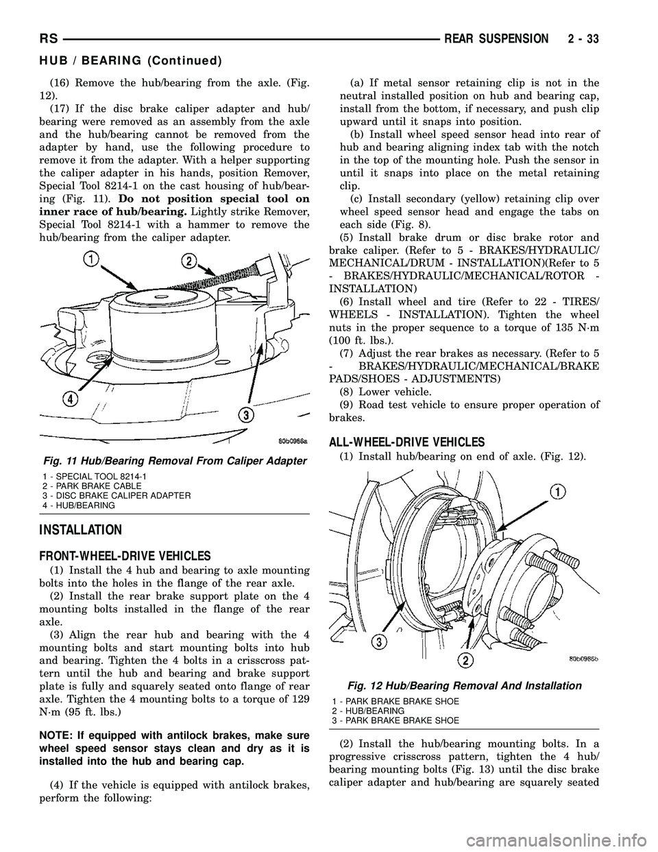
(16) Remove the hub/bearing from the axle. (Fig.
12).
(17) If the disc brake caliper adapter and hub/
bearing were removed as an assembly from the axle
and the hub/bearing cannot be removed from the
adapter by hand, use the following procedure to
remove it from the adapter. With a helper supporting
the caliper adapter in his hands, position Remover,
Special Tool 8214-1 on the cast housing of hub/bear-
ing (Fig. 11).Do not position special tool on
inner race of hub/bearing.Lightly strike Remover,
Special Tool 8214-1 with a hammer to remove the
hub/bearing from the caliper adapter.
INSTALLATION
FRONT-WHEEL-DRIVE VEHICLES
(1) Install the 4 hub and bearing to axle mounting
bolts into the holes in the flange of the rear axle.
(2) Install the rear brake support plate on the 4
mounting bolts installed in the flange of the rear
axle.
(3) Align the rear hub and bearing with the 4
mounting bolts and start mounting bolts into hub
and bearing. Tighten the 4 bolts in a crisscross pat-
tern until the hub and bearing and brake support
plate is fully and squarely seated onto flange of rear
axle. Tighten the 4 mounting bolts to a torque of 129
N´m (95 ft. lbs.)
NOTE: If equipped with antilock brakes, make sure
wheel speed sensor stays clean and dry as it is
installed into the hub and bearing cap.
(4) If the vehicle is equipped with antilock brakes,
perform the following:(a) If metal sensor retaining clip is not in the
neutral installed position on hub and bearing cap,
install from the bottom, if necessary, and push clip
upward until it snaps into position.
(b) Install wheel speed sensor head into rear of
hub and bearing aligning index tab with the notch
in the top of the mounting hole. Push the sensor in
until it snaps into place on the metal retaining
clip.
(c) Install secondary (yellow) retaining clip over
wheel speed sensor head and engage the tabs on
each side (Fig. 8).
(5) Install brake drum or disc brake rotor and
brake caliper. (Refer to 5 - BRAKES/HYDRAULIC/
MECHANICAL/DRUM - INSTALLATION)(Refer to 5
- BRAKES/HYDRAULIC/MECHANICAL/ROTOR -
INSTALLATION)
(6) Install wheel and tire (Refer to 22 - TIRES/
WHEELS - INSTALLATION). Tighten the wheel
nuts in the proper sequence to a torque of 135 N´m
(100 ft. lbs.).
(7) Adjust the rear brakes as necessary. (Refer to 5
- BRAKES/HYDRAULIC/MECHANICAL/BRAKE
PADS/SHOES - ADJUSTMENTS)
(8) Lower vehicle.
(9) Road test vehicle to ensure proper operation of
brakes.
ALL-WHEEL-DRIVE VEHICLES
(1) Install hub/bearing on end of axle. (Fig. 12).
(2) Install the hub/bearing mounting bolts. In a
progressive crisscross pattern, tighten the 4 hub/
bearing mounting bolts (Fig. 13) until the disc brake
caliper adapter and hub/bearing are squarely seatedFig. 11 Hub/Bearing Removal From Caliper Adapter
1 - SPECIAL TOOL 8214-1
2 - PARK BRAKE CABLE
3 - DISC BRAKE CALIPER ADAPTER
4 - HUB/BEARING
Fig. 12 Hub/Bearing Removal And Installation
1 - PARK BRAKE BRAKE SHOE
2 - HUB/BEARING
3 - PARK BRAKE BRAKE SHOE
RSREAR SUSPENSION2-33
HUB / BEARING (Continued)
Page 114 of 2339
STANDARD PROCEDURE
STANDARD PROCEDURE - PARKING
BRAKE AUTOMATIC ADJUSTER TENSION
RELEASE...........................63
STANDARD PROCEDURE - PARKING
BRAKE AUTOMATIC ADJUSTER TENSION
RESET.............................64
STANDARD PROCEDURE - CABLE END
CLEANING AND LUBRICATION...........65
ADJUSTMENTS
ADJUSTMENT - PARKING BRAKE
CABLES............................65
CABLE - PARKING BRAKE FRONT
REMOVAL
REMOVAL...........................66
REMOVAL - FOLD-IN-FLOOR SEATING.....66
REMOVAL - EXPORT..................67
INSTALLATION
INSTALLATION.......................67
INSTALLATION - FOLD-IN-FLOOR SEATING . 68
INSTALLATION - EXPORT...............68
CABLE - PARKING BRAKE INTERMEDIATE
REMOVAL.............................69
INSTALLATION.........................69CABLE - PARKING BRAKE REAR
REMOVAL
REMOVAL - RIGHT REAR...............70
REMOVAL - LEFT REAR................71
REMOVAL - FOLD-IN-FLOOR SEATING.....72
INSTALLATION
INSTALLATION - RIGHT REAR...........74
INSTALLATION - LEFT REAR............75
INSTALLATION - FOLD-IN-FLOOR
SEATING............................75
LEVER - PARKING BRAKE
REMOVAL.............................75
INSTALLATION.........................76
LEVER - PARKING BRAKE (EXPORT)
REMOVAL - PARKING BRAKE LEVER AND
FRONT CABLE.......................77
INSTALLATION - PARKING BRAKE LEVER
AND FRONT CABLE...................77
SHOES - PARKING BRAKE
REMOVAL.............................78
INSTALLATION.........................84
ADJUSTMENTS
ADJUSTMENT - PARKING BRAKE SHOES . . 85
BRAKES - BASE
DESCRIPTION
DESCRIPTION - BASE BRAKES
The base brake system consists of the following
components:
²Brake pedal
²Power brake booster
²Master cylinder
²Brake tubes and hoses
²Proportioning valve (non-ABS vehicles only)
²Disc brakes
²Drum brakes
²Brake lamp switch
²Brake fluid level switch
²Parking brakes
Front disc brakes control the braking of the front
wheels; rear braking is controlled by rear drum
brakes or rear disc brakes depending on options.
The hydraulic brake system is diagonally split on
both the non-antilock braking systems and antilock
braking systems. That means the left front and right
rear brakes are on one hydraulic circuit and the right
front and left rear are on the other.
For information on the brake lamp switch, (Refer
to 8 - ELECTRICAL/LAMPS/LIGHTING - EXTERI-
OR/BRAKE LAMP SWITCH - DESCRIPTION)Vehicles equipped with the optional antilock brake
system (ABS) use a system designated Mark 20e. It
is available with or without traction control. This
system shares most base brake hardware used on
vehicles without ABS. ABS components are described
in detail in ANTILOCK BRAKE SYSTEM.DESCRIPTION - BASE BRAKES (EXPORT)
Four-Wheel Disc Antilock Brakes are standard on
all models.
OPERATION - BASE BRAKES
When a vehicle needs to be stopped, the driver
applies the brake pedal. The brake pedal pushes the
input rod of the power brake booster into the booster.
The booster uses vacuum to ease pedal effort as force
is transferred through the booster to the master cyl-
inder. The booster's output rod pushes in the master
cylinder's primary and secondary pistons applying
hydraulic pressure through the chassis brake tubes
to the brakes at each tire and wheel assembly.
The parking brakes are foot-operated. When
applied, the parking brake lever pulls on cables that
actuate brake shoes at each rear wheel. These shoes
come in contact with a hub mounted drum (drum for
disc/drum brakes or drum-in-hat for disc/disc brakes)
and hold it in place.
RSBRAKES - BASE5-3