spare tire CHRYSLER CARAVAN 2005 Service Manual
[x] Cancel search | Manufacturer: CHRYSLER, Model Year: 2005, Model line: CARAVAN, Model: CHRYSLER CARAVAN 2005Pages: 2339, PDF Size: 59.69 MB
Page 1758 of 2339
TIRES/WHEELS
TABLE OF CONTENTS
page page
TIRES/WHEELS
DIAGNOSIS AND TESTING - TIRE AND
WHEEL VIBRATION.....................1
STANDARD PROCEDURE
STANDARD PROCEDURE - TIRE AND
WHEEL BALANCE......................5
STANDARD PROCEDURE - TIRE AND
WHEEL MATCH MOUNTING..............7
STANDARD PROCEDURE - TIRE AND
WHEEL ROTATION.....................7
REMOVAL
REMOVAL - TIRE AND WHEEL ASSEMBLY
(ALUMINUM WHEEL)....................8
REMOVAL - TIRE AND WHEEL ASSEMBLY
(STEEL WHEEL).......................8
INSTALLATION
INSTALLATION - TIRE AND WHEEL
ASSEMBLY (ALUMINUM WHEEL)..........8
INSTALLATION - TIRE AND WHEEL
ASSEMBLY (STEEL WHEEL)..............8
TIRE PRESSURE MONITORING
DESCRIPTION..........................9
OPERATION...........................10
SENSOR - TPM
DESCRIPTION.........................10
OPERATION...........................10
CAUTION.............................11
DIAGNOSIS AND TESTING - TIRE PRESSURE
SENSOR............................11
REMOVAL.............................11
INSTALLATION.........................11
TIRES
DESCRIPTION
DESCRIPTION - TIRE..................13
DESCRIPTION - RADIAL-PLY TIRES.......13
DESCRIPTION - REPLACEMENT TIRES....14
DESCRIPTION - SPARE TIRE
(TEMPORARY).......................14DIAGNOSIS AND TESTING
DIAGNOSIS AND TESTING - TIRE NOISE . . . 14
DIAGNOSIS AND TESTING - TIRE/VEHICLE
LEAD...............................14
DIAGNOSIS AND TESTING - TIRE WEAR
PATTERNS..........................16
DIAGNOSIS AND TESTING - TREAD WEAR
INDICATORS.........................16
STANDARD PROCEDURE
STANDARD PROCEDURE - TIRE INFLATION
PRESSURES.........................16
STANDARD PROCEDURE - TIRE
PRESSURE FOR HIGH SPEED
OPERATION.........................17
STANDARD PROCEDURE - TIRE LEAK
REPAIRING..........................17
CLEANING - TIRES.....................18
WHEELS
DESCRIPTION - WHEEL..................18
DIAGNOSIS AND TESTING - WHEEL
INSPECTION.........................19
CLEANING
WHEEL AND WHEEL TRIM CARE.........19
SPECIFICATIONS
WHEEL.............................19
WHEEL COVER
DESCRIPTION.........................19
REMOVAL.............................19
INSTALLATION.........................20
WHEEL MOUNTING STUDS - FRONT
REMOVAL.............................21
INSTALLATION.........................21
WHEEL MOUNTING STUDS - REAR
REMOVAL.............................22
INSTALLATION.........................22
TIRES/WHEELS
DIAGNOSIS AND TESTING - TIRE AND WHEEL
VIBRATION
Tire and wheel imbalance, runout and force varia-
tion can cause vehicles to exhibit steering wheel
vibration.
VISUAL INSPECTION
Visual inspection of the vehicle is recommended
prior to road testing or performing any other proce-
dure. Raise vehicle on a suitable hoist. (Refer to
LUBRICATION & MAINTENANCE/HOISTING -
STANDARD PROCEDURE)
Inspect for the following:
²Verify correct (OEM) wheel and tire, as well as
correct wheel weights. Aluminum wheels require
RSTIRES/WHEELS22-1
Page 1764 of 2339

If difficult to balance, break down the wheel and
tire assembly and check for loose debris inside tire.
Prior to disassembly, mark (index) the tire at the
valve stem. Use this mark in order to remount the
tire in its original orientation with respect to the
wheel.
STANDARD PROCEDURE - TIRE AND WHEEL
MATCH MOUNTING
Wheels and tires are match mounted at the factory.
This means that the high spot of the tire is matched
to the low spot on the wheel rim. This technique is
used to reduce runout in the wheel and tire assem-
bly. The high spot on the tire is marked with a paint
mark or a bright colored adhesive label on the out-
board sidewall. The low spot on the wheel is identi-
fied with a label on the outside of the rim and a dot
or line in the drop well area of the rim (inside where
the tire mounts). If the outside label has been
removed, the tire will have to be removed to locate
the dot or line on the inside of the rim. The tire can
then be match mounted to the tire.
Information on match mounting the tire to the
wheel can be found in Tire and Wheel Runout/Match
Mounting, items (2) through (5), within Diagnosis
And Testing - Tire And Wheel Vibration. (Refer to 22
- TIRES/WHEELS - DIAGNOSIS AND TESTING)
STANDARD PROCEDURE - TIRE AND WHEEL
ROTATION
NON-DIRECTIONAL TREAD PATTERN TIRES
Tires on the front and rear axles operate at differ-
ent loads and perform different functions. For these
reasons, they wear at unequal rates, and tend to
develop irregular wear patterns. These effects can bereduced by timely rotation of tires. The benefits of
rotation are especially worthwhile. Rotation will
increase tread life, help to maintain mud, snow, and
wet traction levels, and contribute to a smooth, quiet
ride.
The suggested rotation method is the forward-cross
tire rotation method (Fig. 11). This method takes
advantage of current tire industry practice which
allows rotation of radial-ply tires. Other rotation
methods may be used, but may not have all the ben-
efits of the recommended method.
NOTE: Only the 4 tire rotation method may be used
if the vehicle is equipped with a low mileage or tem-
porary spare tire.
DIRECTIONAL TREAD PATTERN TIRES
Some vehicles are fitted with special high-perfor-
mance tires having a directional tread pattern. These
tires are designed to improve traction on wet pave-
ment. To obtain the full benefits of this design, the
tires must be installed so that they rotate in the cor-
rect direction. This is indicated by arrows on the tire
sidewalls.
When wheels and tires are being installed, extra
care is needed to ensure that this direction of rota-
tion is maintained.
Refer to Owner's Manual for rotation schedule.
Fig. 10 Aluminum Wheel Weight
1 - TIRE
2 - WHEEL
3 - WHEEL WEIGHT
Fig. 11 Forward-Cross Tire Rotation Method
RSTIRES/WHEELS22-7
TIRES/WHEELS (Continued)
Page 1766 of 2339
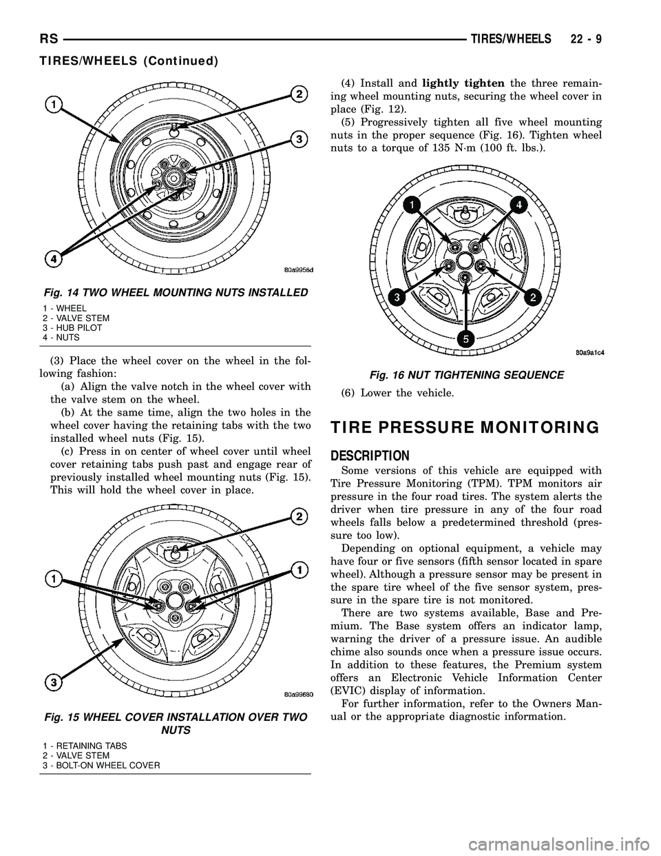
(3) Place the wheel cover on the wheel in the fol-
lowing fashion:
(a) Align the valve notch in the wheel cover with
the valve stem on the wheel.
(b) At the same time, align the two holes in the
wheel cover having the retaining tabs with the two
installed wheel nuts (Fig. 15).
(c) Press in on center of wheel cover until wheel
cover retaining tabs push past and engage rear of
previously installed wheel mounting nuts (Fig. 15).
This will hold the wheel cover in place.(4) Install andlightly tightenthe three remain-
ing wheel mounting nuts, securing the wheel cover in
place (Fig. 12).
(5) Progressively tighten all five wheel mounting
nuts in the proper sequence (Fig. 16). Tighten wheel
nuts to a torque of 135 N´m (100 ft. lbs.).
(6) Lower the vehicle.
TIRE PRESSURE MONITORING
DESCRIPTION
Some versions of this vehicle are equipped with
Tire Pressure Monitoring (TPM). TPM monitors air
pressure in the four road tires. The system alerts the
driver when tire pressure in any of the four road
wheels falls below a predetermined threshold (pres-
sure too low).
Depending on optional equipment, a vehicle may
have four or five sensors (fifth sensor located in spare
wheel). Although a pressure sensor may be present in
the spare tire wheel of the five sensor system, pres-
sure in the spare tire is not monitored.
There are two systems available, Base and Pre-
mium. The Base system offers an indicator lamp,
warning the driver of a pressure issue. An audible
chime also sounds once when a pressure issue occurs.
In addition to these features, the Premium system
offers an Electronic Vehicle Information Center
(EVIC) display of information.
For further information, refer to the Owners Man-
ual or the appropriate diagnostic information.
Fig. 14 TWO WHEEL MOUNTING NUTS INSTALLED
1 - WHEEL
2 - VALVE STEM
3 - HUB PILOT
4 - NUTS
Fig. 15 WHEEL COVER INSTALLATION OVER TWO
NUTS
1 - RETAINING TABS
2 - VALVE STEM
3 - BOLT-ON WHEEL COVER
Fig. 16 NUT TIGHTENING SEQUENCE
RSTIRES/WHEELS22-9
TIRES/WHEELS (Continued)
Page 1767 of 2339
OPERATION
The Tire Pressure Monitoring (TPM) system uses
radio and sensor technology to monitor tire air pres-
sure levels. Sensors, mounted to each road wheel as
part of the valve stem, transmit a low frequency indi-
cating their individual pressure to a receiver located
in the Wireless Control Module (WCM) portion of the
Sentry Key Remote Electronic Entry Module
(SKREEM). These transmissions occur approximately
once every minute at speeds over 20 mph (32 km/h).
The Tire Pressure Monitoring system remains active
even if no tire pressure related message is displayed.
The sensors lay dormant (Park Mode), then wake
and start transmitting (Drive Mode) when the vehicle
first reaches speeds over 20 mph (32 km/h). Once the
wheels stop rotating for a period of approximately 30
minutes, the sensors shut down until again awaken.
Although not transmitting as when in Drive Mode,
while in Park Mode, the sensors still transmit
approximately once every 13 hours to let the receiver
know air pressure status at that time.
The receiver only receives information from the
four rotating tires. A fifth sensor may be located in
the spare tire wheel, depending on vehicle options.
Although this fifth sensor may be present, it does not
broadcast any information because it does not rotate.
When the system detects that a tire is going low,
below the Low Pressure (lamp) ON Threshold (See
following table), the driver is alerted to the situation.
The Base system illuminates an indicator lamp,
warning the driver of a pressure issue and sounds an
audible chime. In equipped with the Premium sys-
tem, the information is also displayed on the Elec-
tronic Vehicle Information Center (EVIC).
Once pressure in the suspect tire raises above the
Low Pressure (lamp) OFF Threshold, the lamp will
go out and the system returns to normal.
TPM THRESHOLD PRESSURES
DESCRIPTION SPECIFICATION
Placard Pressure (Cold) 36 PSI (248 kPa)
Low Pressure OFF Threshold 33 PSI (228 kPa)
Low Pressure ON Threshold 28 PSI (193 kPa)
SENSOR - TPM
DESCRIPTION
On vehicles equipped with Tire Pressure Monitor-
ing, one tire pressure sensor is mounted to each road
wheel (Fig. 18), and depending on factory wheel
options, a sensor may be located in the spare tire
wheel. Both aluminum and steel wheels are used in
this system, although sensors for one type wheel can-
not be used in the other type wheel.Each sensor has an internal battery that lasts up
to 10 years. The battery is not serviceable. At the
time of battery failure, the sensor must be replaced.
The serviceable components of the tire pressure sen-
sor are:
²Sensor-To-Wheel Grommet
²Valve Stem Cap
²Valve Stem Core
Valve stem caps and cores are specifically designed
for the tire pressure monitoring sensors. Although
similar to standard valve stem caps and cores, they
are different.
CAUTION: Do not use a standard valve stem cap or
core in a tire pressure sensor. Always use the orig-
inal equipment style sensor cap and core.
CAUTION: Do not reuse the Sensor-To-Wheel Grom-
met. Always use a new grommet when installing a
pressure sensor and properly torque the sensor
nut.
CAUTION: Do not attempt to install a tire pressure
sensor in an aftermarket wheel. Use only in original
style factory wheels.
OPERATION
The battery operated tire pressure sensors lay dor-
mant (Park Mode), then wake and start transmitting
(Drive Mode) when the vehicle first reaches speeds
over 20 mph (32 km/h). Once the wheels stop rotat-
ing for a period of approximately 30 minutes, the
sensors shut down until again awaken. Although not
transmitting as when in Drive Mode, while in Park
Mode, the sensors still transmit approximately once
every 13 hours to let the receiver know air pressure
status at that time.
Each sensor transmits tire pressure data approxi-
mately once every minute. Each sensor's (transmit-
ter) broadcast is uniquely coded so that the wireless
control module (WCM) can monitor the state of each
of the sensors on the four rotating road wheels. The
WCM (located in the SKREEM) automatically learns
and stores the sensor's ID while driving after a sen-
sor has been replaced. There is no retraining neces-
sary.
The receiver only receives information from the
four rotating tires. A fifth sensor may be located in
the spare tire wheel, depending on vehicle options.
Although this fifth sensor may be present, it does not
broadcast any information because it does not rotate.
For additional information, refer to Appropriate
Diagnostic Information.
22 - 10 TIRES/WHEELSRS
TIRE PRESSURE MONITORING (Continued)
Page 1771 of 2339

Radial-ply tires must always be used in sets of four
and under no circumstances should they be used on
the front only. It is recommended that tires from dif-
ferent manufacturers NOT be mixed. They may be
mixed with a temporary spare tire when necessary. A
maximum speed of 80 km/h (50 mph) is recom-
mended while a temporary spare is in use.
Radial-ply tires have the same load-carrying capac-
ity as other types of tires of the same size. They also
use the same recommended inflation pressures.
DESCRIPTION - REPLACEMENT TIRES
WARNING: FAILURE TO EQUIP THE VEHICLE WITH
TIRES HAVING ADEQUATE SPEED CAPABILITY
CAN RESULT IN SUDDEN TIRE FAILURE.
WARNING: IN ORDER TO MAINTAIN THE SPEED
CAPABILITY OF THE VEHICLE, REPLACEMENT
TIRES MUST HAVE SPEED RATINGS EQUAL TO OR
HIGHER THAN THOSE FITTED TO THE VEHICLE AS
ORIGINAL EQUIPMENT. IF TIRES WITH LOWER
SPEED RATINGS ARE FITTED, THE VEHICLE'S
HANDLING MAY BE AFFECTED AND THE SPEED
CAPABILITY OF THE VEHICLE MAY BE LOWERED
TO THE MAXIMUM SPEED CAPABILITY OF THE
REPLACEMENT TIRES. TO AVOID AN ACCIDENT
RESULTING IN SEVERE OR FATAL INJURY, CON-
SULT THE TIRE MANUFACTURER IN REGARDS TO
MAXIMUM SPEED RATINGS.
It is recommended that tires equivalent to the orig-
inal equipment tires be used when replacement is
needed.
Failure to use equivalent replacement tires may
adversely affect the safety and handling of the vehi-
cle.
The original equipment tires provide a proper com-
bination of many characteristics such as:
²Ride
²Noise
²Handling
²Durability
²Tread life²Traction
²Rolling resistance
²Speed capability
The use of tires smaller than the minimum tire
size approved for the vehicle can result in tire over-
loading and failure.
Use tires that have the approved load rating for
the vehicle and never overload them. Failure to equip
the vehicle with tires having adequate speed capabil-
ity can result in sudden tire failure and loss of vehi-
cle control.
The use of oversize tires may cause interference
with vehicle components. Under extremes of suspen-
sion and steering travel, interference with vehicle
components may cause tire damage.
DESCRIPTION - SPARE TIRE (TEMPORARY)
The temporary (convenience) spare tire is designed
for emergency use only. The original tire should be
repaired and reinstalled, or replaced with a new, at
the first opportunity.
The temporary (convenience) spare tire should be
inflated to the pressure listed on its sidewall. Do not
exceed speeds of 80 km/h (50 mph) when the tempo-
rary spare tire is in use on the vehicle. Refer to the
Owner's Manual for more details.
DIAGNOSIS AND TESTING
DIAGNOSIS AND TESTING - TIRE NOISE
Unusual tire noise can be associated with tire and
wheel vibration or irregular tire wear. For vibration,
(Refer to 22 - TIRES/WHEELS - DIAGNOSIS AND
TESTING). For irregular tire wear, (Refer to 22 -
TIRES/WHEELS/TIRES - DIAGNOSIS AND TEST-
ING).
DIAGNOSIS AND TESTING - TIRE/VEHICLE
LEAD
Use the following Vehicle Lead Diagnosis And Cor-
rection Chart to diagnose and correct a vehicle lead
or drift problem.
22 - 14 TIRES/WHEELSRS
TIRES (Continued)
Page 1861 of 2339
CARPETS - FOLD-IN-FLOOR
REMOVAL
(1) Remove floor mats.
(2) Remove front seats. (Refer to 23 - BODY/
SEATS/SEAT - REMOVAL)
(3) Remove instrument panel lower console. (Refer
to 23 - BODY/INSTRUMENT PANEL/STORAGE
BIN - REMOVAL).
(4) Remove the floor console base tray and discon-
nect wire connector from the base tray.(Refer to 23 -
BODY/INTERIOR/FLOOR CONSOLE BASE TRAY -
REMOVAL)
(5) Remove heel blocker (plastic block below accel-
erator pedal).
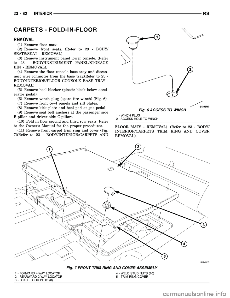
(6) Remove winch plug (spare tire winch) (Fig. 6).
(7) Remove front cowl panels and sill plates.
(8) Remove kick plate and heel pad at gas pedal
(9) Remove seat belt anchors at the passenger side
B-pillar and driver side C-pillars
(10) Fold in floor second and third row seats. Refer
to the Owner's Manual for the proper procedures.
(11) Remove front carpet trim ring and cover (Fig.
7)(Refer to 23 - BODY/INTERIOR/CARPETS ANDFLOOR MATS - REMOVAL). (Refer to 23 - BODY/
INTERIOR/CARPETS TRIM RING AND COVER
REMOVAL).
Fig. 6 ACCESS TO WINCH
1 - WINCH PLUG
2 - ACCESS HOLE TO WINCH
Fig. 7 FRONT TRIM RING AND COVER ASSEMBLY
1 - FORWARD 4-WAY LOCATOR
2 - REARWARD 2-WAY LOCATOR
3 - LOAD FLOOR PLUG (8)4 - WELD STUD NUTS (10)
5 - TRIM RING COVER
23 - 82 INTERIORRS
Page 1863 of 2339
(3) Roll carpet forward under instrument panel
(Fig. 8).
(4) Install push pins fasteners through carpet and
grommet into floor to attach carpet to floor in front
seat area.
(5) Pull wire harnesses through the carpet as
needed.
(6) Smooth out the carpet and allowing weld studs
to go all the way through the carpet.
(7) Install rear push pins fasteners attaching rear
of carpet.
(8) Place third row carpet cover into position and
press clips into position (Fig. 9).
(9) Slide the carpet under the quarter trim panel
into position.
(10) Install lower B-pillar trim covers.
(11) Install sliding door sill plates. (Refer to 23 -
BODY/INTERIOR/SLIDING DOOR SILL PLATE -
INSTALLATION).
(12) Install front carpet trim ring and cover (Fig.
7). (Refer to 23 - BODY/INTERIOR/CARPETS TRIM
RING AND COVER - INSTALLATION)
(13) Install seat belt anchors at the passenger side
B-pillar and driver side C-pillars
(14) Install kick plate and heel pad at the gas
pedal
(15) Install winch plug (spare tire winch) (Fig. 6).
(16) Install front cowl panels and sill plates.
(17) Install heel blocker (plastic block below accel-
erator pedal).
(18) Install the floor console base tray and discon-
nect wire connector from the base tray. (Refer to 23 -
BODY/INTERIOR/FLOOR CONSOLE BASE TRAY -
INSTALLATION).
(19) Install instrument panel lower console. (Refer
to 23 - BODY/INSTRUMENT PANEL/STORAGE
BIN - INSTALLATION).
(20) Install front seats. (Refer to 23 - BODY/
SEATS/SEAT - REMOVAL).
(21) Install floor mats.CARPET TRIM RING AND
COVER - FOLD-IN-FLOOR
REMOVAL
(1) Move front seats to the full forward position.
(2) Fold the second row seats into the floor.
(3) Remove the load floor plugs (Fig. 10).
(4) Remove the ten weld nuts.
(5) Open door covers (Fig. 11).
(6) Remove the four inter weld nuts (Fig. 12).
(7) Raise the front trim ring and cover up off of
the weld studs and remove from vehicle.
INSTALLATION
(1) Place front trim ring and cover assembly into
position.
(2) Open door covers (Fig. 11).
(3) Install the four inter weld nuts (Fig. 12).
(4) Close door covers.
(5) Install the ten weld nuts (Fig. 10).
(6) Install the eight load floor plugs.
(7) Open the second row seats into position.
(8) Move front seats to the position.
23 - 84 INTERIORRS
CARPETS - FOLD-IN-FLOOR (Continued)
Page 1888 of 2339
If any of the remaining OCS components of the
passenger side front seat cushion require replace-
ment, they are serviced only as a factory-calibrated,
assembled, and tamper-evident service replacement
package. This package includes the assembled frame,
springs, pad, bladder, sensor, foam, wiring and a cal-
ibrated OCM. When installing this package, always
replace all of the existing components with the new
components as a unit. Do not attempt to separate or
disconnect any of the new OCS components con-
tained in the service replacement package from each
other, and do not attempt to reuse any of the
replaced components in this or any other vehicle.
Once any of the original factory-installed compo-
nents except the OCM have been replaced with the
service replacement package components, the OCM
can only be serviced by replacing the entire passen-
ger side front seat cushion unit with another com-
plete service replacement package. (Refer to 23 -
BODY/SEATS/SEAT CUSHION - FRONT -
REMOVAL).
WARNING: TO AVOID PERSONAL INJURY OR
DEATH, ON VEHICLES EQUIPPED WITH AIRBAGS,
DISABLE THE SUPPLEMENTAL RESTRAINT SYS-
TEM BEFORE ATTEMPTING ANY STEERING
WHEEL, STEERING COLUMN, AIRBAG, OCCUPANT
CLASSIFICATION SYSTEM, SEAT BELT TEN-
SIONER, IMPACT SENSOR, OR INSTRUMENT
PANEL COMPONENT DIAGNOSIS OR SERVICE.
DISCONNECT AND ISOLATE THE BATTERY NEGA-
TIVE (GROUND) CABLE, THEN WAIT TWO MINUTES
FOR THE SYSTEM CAPACITOR TO DISCHARGE
BEFORE PERFORMING FURTHER DIAGNOSIS OR
SERVICE. THIS IS THE ONLY SURE WAY TO DIS-
ABLE THE SUPPLEMENTAL RESTRAINT SYSTEM.
FAILURE TO TAKE THE PROPER PRECAUTIONS
COULD RESULT IN ACCIDENTAL AIRBAG DEPLOY-
MENT.
WARNING: TO AVOID PERSONAL INJURY OR
DEATH ON VEHICLES EQUIPPED WITH THE OCCU-
PANT CLASSIFICATION SYSTEM (OCS), ONLY THE
OCCUPANT CLASSIFICATION MODULE (OCM) AND
THE SEAT CUSHION TRIM MAY BE SERVICED SEP-
ARATELY. ALL OTHER COMPONENTS OF THE PAS-
SENGER SIDE FRONT SEAT CUSHION ASSEMBLY
MUST BE SERVICED ONLY AS A COMPLETE FAC-
TORY-CALIBRATED, ASSEMBLED AND TAMPER-EV-
IDENT SERVICE REPLACEMENT PACKAGE. THIS
PACKAGE INCLUDES THE FRAME, SPRINGS, PAD,
BLADDER, SENSOR, FOAM, WIRING AND A CALI-
BRATED OCM. WHEN INSTALLING THIS PACKAGE
ALWAYS REPLACE ALL OF THE EXISTING COMPO-
NENTS WITH THE NEW COMPONENTS AS A UNIT.
DO NOT ATTEMPT TO SEPARATE OR DISCONNECTANY OF THE NEW OCS COMPONENTS IN THE SER-
VICE REPLACEMENT PACKAGE FROM EACH
OTHER, AND DO NOT ATTEMPT TO REUSE ANY OF
THE REPLACED COMPONENTS IN THIS OR ANY
OTHER VEHICLE. FAILURE TO TAKE THE PROPER
PRECAUTIONS COULD RESULT IN FAILURE OF
THE PASSENGER AIRBAG TO DEPLOY WHEN
REQUIRED, OR IN PASSENGER AIRBAG DEPLOY-
MENT WHEN NOT REQUIRED.
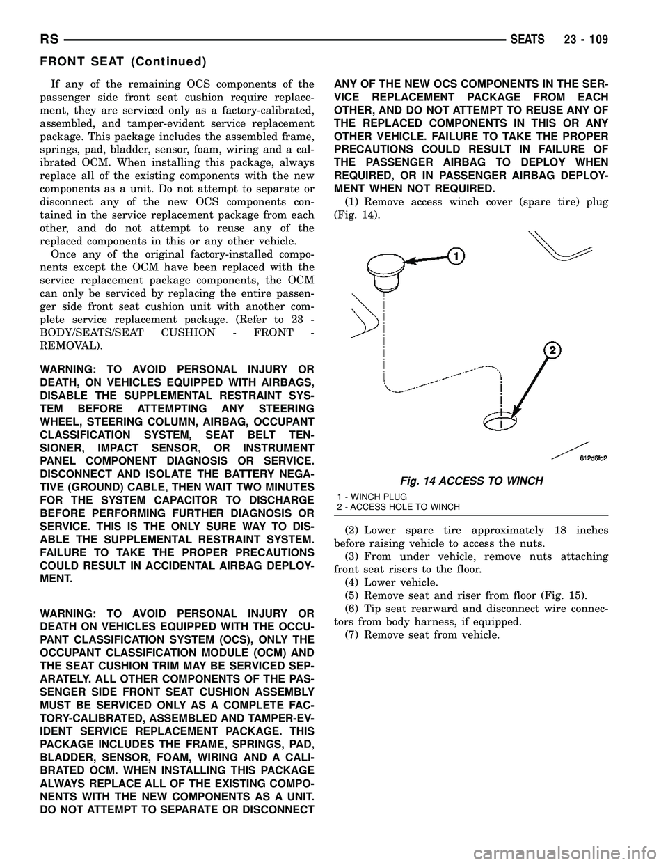
(1) Remove access winch cover (spare tire) plug
(Fig. 14).
(2) Lower spare tire approximately 18 inches
before raising vehicle to access the nuts.
(3) From under vehicle, remove nuts attaching
front seat risers to the floor.
(4) Lower vehicle.
(5) Remove seat and riser from floor (Fig. 15).
(6) Tip seat rearward and disconnect wire connec-
tors from body harness, if equipped.
(7) Remove seat from vehicle.
Fig. 14 ACCESS TO WINCH
1 - WINCH PLUG
2 - ACCESS HOLE TO WINCH
RSSEATS23 - 109
FRONT SEAT (Continued)
Page 1889 of 2339

INSTALLATION
A non-calibrated Occupant Classification Module
(OCM) is the only component of the Occupant Clas-
sification System (OCS) that is available for separate
service replacement, as outlined in the procedures
that follow. The OCS components of the passenger
side front seat cushion including the cushion frame,
springs, pad, occupant detection bladder, pressure
sensor, seat cushion foam and the OCM are a factory-
calibrated and assembled unit. Once this unit is con-
nected to a vehicle electrically, the calibration
settings are uploaded from the OCM and stored in
the memory of the Airbag Control Module (ACM). If
only the OCM is subsequently replaced, the new,
non-calibrated OCM learns the proper calibration
settings from the ACM after it is connected to the
vehicle electrically.
If any of the remaining OCS components of the
passenger side front seat cushion require replace-
ment, they are serviced only as a factory-calibrated,
assembled, and tamper-evident service replacement
package. This package includes the assembled frame,
springs, pad, bladder, sensor, foam, wiring and a cal-
ibrated OCM. When installing this package, always
replace all of the existing components with the new
components as a unit. Do not attempt to separate or
disconnect any of the new OCS components con-
tained in the service replacement package from each
other, and do not attempt to reuse any of the
replaced components in this or any other vehicle.
Once any of the original factory-installed compo-
nents except the OCM have been replaced with the
service replacement package components, the OCM
can only be serviced by replacing the entire passen-
ger side front seat cushion unit with another com-plete service replacement package. (Refer to 23 -
BODY/SEATS/SEAT CUSHION - FRONT -
REMOVAL).
WARNING: TO AVOID PERSONAL INJURY OR DEATH,
ON VEHICLES EQUIPPED WITH AIRBAGS, DISABLE
THE SUPPLEMENTAL RESTRAINT SYSTEM BEFORE
ATTEMPTING ANY STEERING WHEEL, STEERING
COLUMN, AIRBAG, OCCUPANT CLASSIFICATION
SYSTEM, SEAT BELT TENSIONER, IMPACT SENSOR,
OR INSTRUMENT PANEL COMPONENT DIAGNOSIS
OR SERVICE. DISCONNECT AND ISOLATE THE BAT-
TERY NEGATIVE (GROUND) CABLE, THEN WAIT
TWO MINUTES FOR THE SYSTEM CAPACITOR TO
DISCHARGE BEFORE PERFORMING FURTHER DIAG-
NOSIS OR SERVICE. THIS IS THE ONLY SURE WAY
TO DISABLE THE SUPPLEMENTAL RESTRAINT SYS-
TEM. FAILURE TO TAKE THE PROPER PRECAU-
TIONS COULD RESULT IN ACCIDENTAL AIRBAG
DEPLOYMENT.
WARNING: TO AVOID PERSONAL INJURY OR
DEATH ON VEHICLES EQUIPPED WITH THE OCCU-
PANT CLASSIFICATION SYSTEM (OCS), ONLY THE
OCCUPANT CLASSIFICATION MODULE (OCM) AND
THE SEAT CUSHION TRIM MAY BE SERVICED SEP-
ARATELY. ALL OTHER COMPONENTS OF THE PAS-
SENGER SIDE FRONT SEAT CUSHION ASSEMBLY
MUST BE SERVICED ONLY AS A COMPLETE FAC-
TORY-CALIBRATED, ASSEMBLED AND TAMPER-EV-
IDENT SERVICE REPLACEMENT PACKAGE. THIS
PACKAGE INCLUDES THE FRAME, SPRINGS, PAD,
BLADDER, SENSOR, FOAM, WIRING AND A CALI-
BRATED OCM. WHEN INSTALLING THIS PACKAGE
ALWAYS REPLACE ALL OF THE EXISTING COMPO-
NENTS WITH THE NEW COMPONENTS AS A UNIT.
DO NOT ATTEMPT TO SEPARATE OR DISCONNECT
ANY OF THE NEW OCS COMPONENTS IN THE SER-
VICE REPLACEMENT PACKAGE FROM EACH
OTHER, AND DO NOT ATTEMPT TO REUSE ANY OF
THE REPLACED COMPONENTS IN THIS OR ANY
OTHER VEHICLE. FAILURE TO TAKE THE PROPER
PRECAUTIONS COULD RESULT IN FAILURE OF
THE PASSENGER AIRBAG TO DEPLOY WHEN
REQUIRED, OR IN PASSENGER AIRBAG DEPLOY-
MENT WHEN NOT REQUIRED.
(1) Place seat into position (Fig. 15).
(2) Tip seat rearward and connect wire connectors
to body harness, if equipped.
(3) Place seat riser studs into openings in the floor.
(4) From under vehicle, install nuts attaching
front seat risers to the floor. Tighten nuts to 88 N´m
(65 ft. lbs.) torque.
(5) Crank winch to raise spare tire into position,
and install winch plug (Fig. 14).
Fig. 15 FRONT SEAT
1 - FRONT SEAT
2 - CONNECTORS
3 - B-PILLAR
23 - 110 SEATSRS
FRONT SEAT (Continued)
Page 2331 of 2339
SLEEVE - THIRD ROW - FOLD-IN-FLOOR- INSTALLATION, HEADREST ...........23-153
SLEEVE - THIRD ROW - FOLD-IN-FLOOR - REMOVAL, HEADREST ..............23-152
SLIDING DOOR - INSTALLATION .........23-29
SLIDING DOOR - REMOVAL ............23-29
SLIDING DOOR ADJUSTMENT, STANDARD PROCEDURE - POWER ......8N-49
SLIDING DOOR ADJUSTMENTS, ADJUSTMENTS ...................... 23-30
SLIDING DOOR CONTROL MODULE - DESCRIPTION ....................... 8E-18
SLIDING DOOR CONTROL MODULE - OPERATION ......................... 8E-18
SLIDING DOOR CONTROL MODULE, DIAGNOSIS AND TESTING .............8E-18
SLIDING DOOR GLASS - INSTALLATION . . 23-163
SLIDING DOOR GLASS - REMOVAL .....23-163
SLIDING DOOR LEARN CYCLE, STANDARD PROCEDURE - POWER ......8N-48
SLIDING DOOR LOCK MOTOR - INSTALLATION ...................... 8N-25
SLIDING DOOR LOCK MOTOR - REMOVAL .......................... 8N-25
SLIDING DOOR MOTOR - DESCRIPTION . . 8N-51
SLIDING DOOR MOTOR - INSTALLATION . . 8N-51
SLIDING DOOR MOTOR - OPERATION ....8N-51
SLIDING DOOR MOTOR - REMOVAL .....8N-51
SLIDING DOOR SILL PLATE - INSTALLATION ....................... 23-99
SLIDING DOOR SILL PLATE - REMOVAL ....23-98
SLIDING DOOR STOP BUMPER BEZEL - INSTALLATION ....................... 23-25
SLIDING DOOR STOP BUMPER BEZEL - REMOVAL .......................... 23-25
SLIDING DOOR SYSTEM - DESCRIPTION, POWER ............................ 8N-40
SLIDING DOOR SYSTEM - OPERATION, POWER ............................ 8N-41
SLIDING DOOR SYSTEM, DIAGNOSIS AND TESTING - POWER ...............8N-42
SLIDING DOOR WEATHERSTRIP - INSTALLATION ...................... 23-168
SLIDING DOOR WEATHERSTRIP - REMOVAL ......................... 23-168
SOCKET - INSTALLATION, STABILIZER ....23-33
SOCKET - REMOVAL, STABILIZER .......23-33
SOLENOID - DESCRIPTION, EVAP/PURGE . 25-13
SOLENOID - DESCRIPTION, SHIFT INTERLOCK .................. 21-113,21-264
SOLENOID - DIAGNOSIS AND TESTING, BRAKE/TRANSMISSION SHIFT
INTERLOCK .................. 21-115,21-266
SOLENOID - INSTALLATION, EVAP/ PURGE ............................. 25-13
SOLENOID - INSTALLATION, SHIFT INTERLOCK .................. 21-116,21-267
SOLENOID - OPERATION, EVAP/PURGE . . . 25-13
SOLENOID - OPERATION, SHIFT INTERLOCK .................. 21-114,21-265
SOLENOID - REMOVAL, EVAP/PURGE .....25-13
SOLENOID - REMOVAL, SHIFT INTERLOCK .................. 21-115,21-266
SOLENOID/PRESSURE SWITCH ASSY - DESCRIPTION ................ 21-117,21-268
SOLENOID/PRESSURE SWITCH ASSY - INSTALLATION ................ 21-119,21-270
SOLENOID/PRESSURE SWITCH ASSY - OPERATION .................. 21-118,21-268
SOLENOID/PRESSURE SWITCH ASSY - REMOVAL ................... 21-118,21-269
SPARE TIRE (TEMPORARY) - DESCRIPTION ....................... 22-14
SPARK PLUG CABLE - DESCRIPTION .....8I-10
SPARK PLUG CABLE RESISTANCE, SPECIFICATIONS ...................... 8I-2
SPARK PLUG, SPECIFICATIONS ...........8I-2
SPEAKER, DIAGNOSIS AND TESTING .....8A-18
SPEED CONTROL - DESCRIPTION ........8P-1
SPEED CONTROL (4 SPEED EATX ONLY) - OPERATION, INTERACTIVE .............8P-2
SPEED OPERATION - STANDARD PROCEDURE, TIRE PRESSURE FOR
HIGH .............................. 22-17
SPEED SENSOR - AWD - INSTALLATION, REAR WHEEL ........................ 5-92
SPEED SENSOR - AWD - REMOVAL, REAR WHEEL ........................ 5-92SPEED SENSOR - DESCRIPTION, ENGINE . 14-30
SPEED SENSOR - FWD - INSTALLATION,
REAR WHEEL ........................ 5-93
SPEED SENSOR - FWD - REMOVAL, REAR WHEEL ........................ 5-93
SPEED SENSOR - INPUT - DESCRIPTION ................ 21-120,21-271
SPEED SENSOR - INPUT - INSTALLATION ................ 21-121,21-272
SPEED SENSOR - INPUT - OPERATION . . 21-120, 21-271
SPEED SENSOR - INPUT - REMOVAL . . . 21-121, 21-272
SPEED SENSOR - INSTALLATION, FRONT WHEEL ............................. 5-92
SPEED SENSOR - OPERATION, ENGINE . . . 14-30
SPEED SENSOR - OUTPUT - DESCRIPTION ................ 21-122,21-273
SPEED SENSOR - OUTPUT - INSTALLATION ................ 21-123,21-274
SPEED SENSOR - OUTPUT - OPERATION .................. 21-122,21-273
SPEED SENSOR - OUTPUT - REMOVAL . . 21-123, 21-274
SPEED SENSOR - REMOVAL, FRONT WHEEL ............................. 5-91
SPEED SENSOR AIR GAP, SPECIFICATIONS - WHEEL ..............5-91
SPIRAL PLATE BATTERY CHARGING, STANDARD PROCEDURE ...............8F-10
SPLASH SHIELD - INSTALLATION, FRONT WHEELHOUSE .................23-57
SPLASH SHIELD - REMOVAL, FRONT WHEELHOUSE ....................... 23-57
SPLICE INFORMATION - DESCRIPTION, CONNECTOR, GROUND ..............8W-01-7
SPLICING - STANDARD PROCEDURE, WIRE ...........................8W -01-15
SPLIT - INSTALLATION, BENCH SEAT RISER - 50/50 ...................... 23-145
SPLIT - REMOVAL, BENCH SEAT RISER - 50/50 ............................. 23-145
SPLIT, BENCH - INSTALLATION, SEAT BACK HINGE COVERS - QUAD BUCKET,
50/50 ............................. 23-146
SPLIT, BENCH - INSTALLATION, SEAT CUSHION COVER - QUAD BUCKET,
50/50 ............................. 23-144
SPLIT, BENCH - REMOVAL, SEAT BACK HINGE COVERS - QUAD BUCKET, 50/50 . . 23-146
SPLIT, BENCH - REMOVAL, SEAT CUSHION COVER - QUAD BUCKET,
50/50 ............................. 23-144
SPRING - AWD - INSTALLATION ..........2-39
SPRING - AWD - REMOVAL .............2-38
SPRING - CARGO - INSTALLATION ........2-40
SPRING - CARGO - REMOVAL ...........2-40
SPRING - FWD - INSTALLATION ..........2-42
SPRING - FWD - REMOVAL .............2-40
SPRING ASSEMBLY - INSTALLATION, QUAD BUCKET SEAT SIDE SHIELD/CUP
HOLDER - FLAP ..................... 23-151
SPRING ASSEMBLY - REMOVAL, QUAD BUCKET SEAT SIDE SHIELD/CUP
HOLDER - FLAP ..................... 23-151
SPRING FRONT - INSTALLATION, BUSHING - LEAF ...................... 2-30
SPRING FRONT - REMOVAL, BUSHING - LEAF ............................... 2-29
SPRING MOUNTS - FRONT - INSTALLATION ........................ 2-43
SPRING MOUNTS - FRONT - REMOVAL ....2-42
SPRING MOUNTS - REAR - INSTALLATION ........................ 2-43
SPRING MOUNTS - REAR - REMOVAL .....2-43
SPRING SHACKLE - INSTALLATION .......2-44
SPRING SHACKLE - REMOVAL ...........2-44
SPRINGS - DESCRIPTION, VALVE ........9-109
SPRINGS - OPERATION, VALVE .........9-109
SPROCKET - INSTALLATION, CRANKSHAFT ................... 9-160,9-67
SPROCKET - INSTALLATION, TIMING CHAIN AND CAMSHAFT ...............9-160
SPROCKET - REMOVAL, CRANKSHAFT . . . 9-159,
9-66
SPROCKET - REMOVAL, TIMING CHAIN AND CAMSHAFT ..................... 9-159SPROCKETS - INSTALLATION,
CAMSHAFT .......................... 9-67
SPROCKETS - REMOVAL, CAMSHAFT ......9-66
STABILIZER - INSTALLATION ...........23-33
STABILIZER - REMOVAL ...............23-33
STABILIZER BAR - DESCRIPTION .....2-16,2-44
STABILIZER BAR - INSPECTION ..........2-17
STABILIZER BAR - INSTALLATION ........2-17
STABILIZER BAR - OPERATION .......2-16,2-44
STABILIZER BAR - REMOVAL ............2-17
STABILIZER BAR CUSHION - INSTALLATION .........................2-4
STABILIZER BAR CUSHION - REMOVAL .....2-4
STABILIZER SOCKET - INSTALLATION ....23-33
STABILIZER SOCKET - REMOVAL ........23-33
STAKING - STANDARD PROCEDURE, HEAT ............................... 23-9
STANDARD 4 CYLINDER - DESCRIPTION . . . 8I-9
STARTER, SPECIFICATIONS .............8F-37
STARTING - DESCRIPTION .............8F-31
STARTING - OPERATION ...............8F-31
STARTING - STANDARD PROCEDURE, JUMP ............................... 0-25
STARTING SYSTEM TEST - DIAGNOSIS AND TESTING ....................... 8F-31
STATE DISPLAY TEST MODE, OPERATION - DRB III T................ 25-10
STEERING - DIAGNOSIS AND TESTING, SUSPENSION .......................... 2-50
STEERING BELT TENSION - STANDARD PROCEDURE, CHECKING POWER ..........7-8
STEERING COLUMN - DESCRIPTION .....19-10
STEERING COLUMN - DIAGNOSIS AND TESTING ........................... 19-11
STEERING COLUMN COVER - INSTALLATION, LOWER ................23-74
STEERING COLUMN COVER - INSTALLATION, OVER .................23-76
STEERING COLUMN COVER - REMOVAL, LOWER ............................ 23-74
STEERING COLUMN COVER - REMOVAL, OVER .............................. 23-76
STEERING FASTENER TORQUE, SPECIFICATIONS - POWER ..............19-9
STEERING FLUID LEVEL CHECKING - STANDARD PROCEDURE, POWER .......19-44
STEERING GEAR, SPECIAL TOOLS - POWER ............................ 19-34
STEERING KNUCKLE - INSPECTION ........2-9
STEERING KNUCKLE - INSTALLATION ......2-9
STEERING KNUCKLE - REMOVAL ..........2-7
STEERING PUMP INITIAL OPERATION - STANDARD PROCEDURE, POWER .......19-37
STEERING PUMP, SPECIAL TOOLS - POWER ............................ 19-44
STEERING, SPECIAL TOOLS - POWER .....19-9
STEERING SYSTEM - DESCRIPTION, POWER ............................. 19-1
STEERING SYSTEM - OPERATION, POWER ............................. 19-1
STEERING SYSTEM DIAGNOSIS CHARTS - DIAGNOSIS AND TESTING .............19-3
STEERING SYSTEM FLOW AND PRESSURE TEST - DIAGNOSIS AND
TESTING, POWER ..................... 19-1
STEERING WHEEL - INSTALLATION ......19-24
STEERING WHEEL - REMOVAL ..........19-23
STEM SEALS - DESCRIPTION, VALVE .....9-114
STEM SEALS - INSTALLATION, VALVE ....9-115
STEM SEALS - REMOVAL, VALVE ........9-115
STOP BUMPER - INSTALLATION .........23-25
STOP BUMPER - REMOVAL ............23-25
STOP BUMPER BEZEL - INSTALLATION, SLIDING DOOR ...................... 23-25
STOP BUMPER BEZEL - REMOVAL, SLIDING DOOR ...................... 23-25
STOP LAMP - INSTALLATION, CENTER HIGH MOUNTED ...................... 8L-6
STOP LAMP - REMOVAL, CENTER HIGH MOUNTED ........................... 8L-6
STOP LAMP UNIT - INSTALLATION, CENTER HIGH MOUNTED ...............8L-6
STOP LAMP UNIT - REMOVAL, CENTER HIGH MOUNTED ...................... 8L-6
STORAGE BIN - INSTALLATION, UNDER SEAT ............................. 23-149
STORAGE BIN - REMOVAL, UNDER SEAT . 23-149
30 INDEXRS
Description Group-Page Description Group-Page Description Group-Page