CHRYSLER CROSSFIRE 2007 1.G Owners Manual
Manufacturer: CHRYSLER, Model Year: 2007, Model line: CROSSFIRE, Model: CHRYSLER CROSSFIRE 2007 1.GPages: 299, PDF Size: 8.26 MB
Page 91 of 299

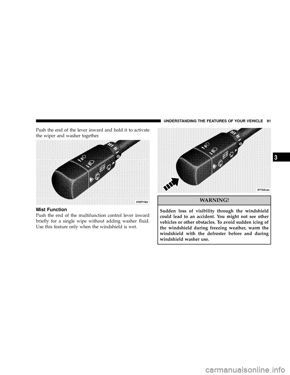
Push the end of the lever inward and hold it to activate
the wiper and washer together.
Mist Function
Push the end of the multifunction control lever inward
briefly for a single wipe without adding washer fluid.
Use this feature only when the windshield is wet.
WARNING!
Sudden loss of visibility through the windshield
could lead to an accident. You might not see other
vehicles or other obstacles. To avoid sudden icing of
the windshield during freezing weather, warm the
windshield with the defroster before and during
windshield washer use.
UNDERSTANDING THE FEATURES OF YOUR VEHICLE 91
3
Page 92 of 299

TELESCOPING STEERING COLUMN
Unlock the steering column by pulling out the handle
located directly below the column. The indicator light
located in the instrument cluster will come on. To
lengthen or shorten the steering column, pull out or push
in the steering wheel. Lock the steering column in
position by pushing the handle in until it engages. The
indicator light in the instrument cluster will go out.WARNING!
Do not adjust the steering wheel while driving. The
telescoping adjustment must be locked while driv-
ing. Adjusting the steering wheel while driving, or
driving without the telescoping adjustment locked
could cause the driver to lose control of the vehicle.
NOTE:If the indicator light in the instrument cluster
does not go out after starting the engine, the telescoping
column is not locked properly. Do not drive the vehicle
until you have properly locked the steering column.
92 UNDERSTANDING THE FEATURES OF YOUR VEHICLE
Page 93 of 299

TIRE PRESSURE MONITOR SYSTEM (if equipped)
Each tire should be checked monthly when cold and
inflated to the inflation pressure recommended by the
vehicle manufacturer on the vehicle placard or tire infla-
tion pressure label. (If your vehicle has tires of a different
size than the size indicated on the vehicle placard or tire
inflation pressure label, you should determine the proper
tire inflation pressure for those tires.)
As an added safety feature, your vehicle has been
equipped with a tire pressure monitoring system (TPMS)
that illuminates a low tire pressure telltale when on ormore of your tires is significantly underÐinflated. Ac-
cordingly, when the low tire pressure telltale illuminates,
you should stop and check your tires as soon as possible,
and inflate them to the proper pressure, Driving on a
significantly under-inflated tire causes the tire to over-
heat and can lead to tire failure. Under-inflation also
reduced fuel efficiency and tire tread life, and may affect
the vehicle's handling and stopping ability.
Please note that the TPMS is not a substitute for proper
tire maintenance, and it is the driver's responsibility to
maintain correct tire pressure, even if under-inflation has
not reached the level to trigger illumination of the TPMS
low tire pressure telltale.
The Tire Pressure Monitor (TPM) system uses wireless
technology to monitor tire pressure levels. Sensors
mounted to each wheel as part of the valve stem transmit
tire pressure readings to a receiver located inside the
vehicle.
NOTE:The TPM system can inform you about a low
tire pressure condition, but it does not replace normal tire
maintenance. The TPM system is not intended to provide
you with notification of rapid tire pressure loss.
UNDERSTANDING THE FEATURES OF YOUR VEHICLE 93
3
Page 94 of 299

CAUTION!
The TPM system is designed to monitor your tire
pressure and will not function as a tire pressure
gauge. After adjusting the air pressure in a tire, there
will be a delay before the system updates the display.The TPM system will cause the indicator lamp in the
instrument cluster to illuminate whenever the pressure in
one tire falls 25% below the recommended pressure
shown on the vehicle's tire label.
NOTE:The pressure in your tires changes with tem-
perature. A significant decrease in temperature could
reduce cold inflation pressure below the TPM setpoint.
For example, tires inflated to the proper cold inflation
pressure on a warm day or in a warm garage could
illuminate the TPM indicator lamp on the following day
if the temperature is very cold.ALWAYScheck the
pressure in your tires if the TPM lamp is illuminated.
94 UNDERSTANDING THE FEATURES OF YOUR VEHICLE
Page 95 of 299

CAUTION!
The TPM system has been optimized for the original
equipment tires and wheels. TPM system pressures
have been established for the tire size equipped on
your vehicle. Undesirable operation or sensor dam-
age may result when using replacement equipment
that is not of the same size, type, and/or style.
Aftermarket wheels can cause sensor damage. Do not
use aftermarket tire sealant or balance beads, as
damage to the sensors may result.
NOTE:The standard TIREFIT system (refer to What To
Do In Emergencies for more information) is specifically
designed to operate in conjunction with the TPM system,
and will not damage the sensors.
If your tire pressure is low, you should correct your tire
inflation pressure as soon as possible and inspect all of
your tires. Low tire pressure will cause the tire pressure
light to illuminate. They will remain on for the rest of the
driving cycle, or until the tire pressure is corrected.
In addition to monitoring tire pressures, the TPM system
also monitors faults within the system. If the TPM light
and alarm continue after the tire pressure has been
corrected, see your authorized dealer.
This device complies with part 15 of FCC rules and with
RSS-210 of Industry Canada. Operation is subject to the
following conditions:
1. This device may not cause harmful interference.
UNDERSTANDING THE FEATURES OF YOUR VEHICLE 95
3
Page 96 of 299

2. This device must accept any interference that may be
received, including interference that may cause undes-
ired operation.
NOTE:Changes and modifications not expressly ap-
proved by the party responsible for compliance could
void the user's authority to operate the equipment.
REAR SPOILER
CAUTION!
Do not push or pull on the spoiler when deployed.
Damage to the spoiler could result.
A rear spoiler enhances vehicle stability. The rear spoiler
deploys automatically when vehicle speed reaches ap-
proximately 62 mph (100 km/h). The spoiler begins to
retract at 39 mph (62 km/h). When retracted, the spoiler
fits between the quarter panels, and aft of the liftgate
window or tonneau cover.The spoiler can also be deployed at lower speeds using
an override switch mounted in the center console.
Once manually deployed, the spoiler will only retract by
pressing the bottom of the spoiler switch. The spoiler will
then retract in steps as long as the switch is depressed. If
the switch is depressed until the spoiler is fully retracted,
a short beep will be heard, and automatic control will be
reestablished.
96 UNDERSTANDING THE FEATURES OF YOUR VEHICLE
Page 97 of 299

The spoiler control also incorporates an emergency stop
feature. If, for any reason, spoiler motion needs to be
stopped, pressing either the top or bottom of the switch
will stop the spoiler motion. Once the deployment speed
is reached, however, the spoiler deploys to its full up
position.
The spoiler will deploy as a safety precaution if the ESP
system detects a large difference in wheel speed between
the front and rear wheels. This could occur as a result of
a speed signal malfunction, or could occur if the vehicle
is attempting to accelerate on a low friction surface
causing the rear wheels to spin. The spoiler will remain
deployed and the warning light in the spoiler switch will
blink until the vehicle is restarted. If the spoiler continues
to deploy in this fashion below the normal deployment
speed, see your authorized dealer.Should a malfunction occur that prevents the spoiler
from deploying automatically, a red warning light will
illuminate in the override switch and an audible warning
will sound.
UNDERSTANDING THE FEATURES OF YOUR VEHICLE 97
3
Page 98 of 299

WARNING!
Do not drive the vehicle at speeds above 62 mph (100
km/h) if the red spoiler warning indicator is illumi-
nated. You could have reduced vehicle stability and
control.
WARNING!
Keep hands and fingers away from the spoiler and
spoiler linkage when the spoiler is deploying or
retracting. The linkage could pinch your fingers and
cause serious injury.
BRAKE ASSIST SYSTEM (BAS)
WARNING!
BAS cannot prevent the natural laws of physics from
acting on the vehicle, nor can it increase braking
efficiency beyond that afforded by the condition of
the vehicle brakes and tires or the traction afforded.
The BAS cannot prevent accidents, including those
resulting from excessive speed in turns, following
another vehicle too closely, or hydroplaning. Only a
safe, attentive, and skillful driver can prevent acci-
dents. The capabilities of a BAS-equipped vehicle
must never be exploited in a reckless or dangerous
manner which could jeopardize the user's safety or
the safety of others.
The BAS is designed to maximize the vehicle's braking
capability during emergency braking maneuvers. The
system applies maximum power boost to the brakes
more quickly in emergency braking conditions than
might otherwise be afforded solely by the driver's brak-
ing style. This can help reduce braking distances. The
98 UNDERSTANDING THE FEATURES OF YOUR VEHICLE
Page 99 of 299

BAS complements the antilock brake system (ABS). Ap-
plying the brakes very quickly results in maximum BAS
assistance. To receive the benefit of the system, you must
apply continuous full braking power during the stopping
sequence. Do not reduce brake pedal pressure.
Once the brake pedal is released, the BAS is deactivated.
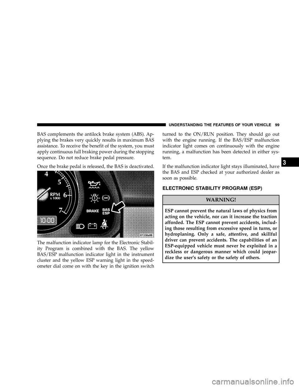
The malfunction indicator lamp for the Electronic Stabil-
ity Program is combined with the BAS. The yellow
BAS/ESP malfunction indicator light in the instrument
cluster and the yellow ESP warning light in the speed-
ometer dial come on with the key in the ignition switchturned to the ON/RUN position. They should go out
with the engine running. If the BAS/ESP malfunction
indicator light comes on continuously with the engine
running, a malfunction has been detected in either sys-
tem.
If the malfunction indicator light stays illuminated, have
the BAS and ESP checked at your authorized dealer as
soon as possible.
ELECTRONIC STABILITY PROGRAM (ESP)
WARNING!
ESP cannot prevent the natural laws of physics from
acting on the vehicle, nor can it increase the traction
afforded. The ESP cannot prevent accidents, includ-
ing those resulting from excessive speed in turns, or
hydroplaning. Only a safe, attentive, and skillful
driver can prevent accidents. The capabilities of an
ESP-equipped vehicle must never be exploited in a
reckless or dangerous manner which could jeopar-
dize the user's safety or the safety of others.
UNDERSTANDING THE FEATURES OF YOUR VEHICLE 99
3
Page 100 of 299

The ESP enhances directional control and reduces driving
wheel spin of the vehicle under various driving condi-
tions.
The ESP system corrects for over/understeering of the
vehicle by applying brakes to the appropriate wheel.
Engine torque is also limited. The ESP warning light,
located in the instrument cluster, starts to flash as soon as
the tires lose traction and the wheels begin to spin.To improve the vehicle's traction when driving with
snow chains, or starting off in deep snow, sand or gravel,
switch off the ESP system by pressing the upper half of
the ESP switch.
With the ESP system switched off, the engine torque
reduction feature is cancelled. Therefore, the enhanced
vehicle stability offered by ESP is unavailable. ESP al-
ways operates under braking, even with the switch in the
OFF position. If one drive wheel loses traction and begins
to spin, the brake is applied by the ESP system until the
100 UNDERSTANDING THE FEATURES OF YOUR VEHICLE