service CHRYSLER CROSSFIRE 2007 1.G User Guide
[x] Cancel search | Manufacturer: CHRYSLER, Model Year: 2007, Model line: CROSSFIRE, Model: CHRYSLER CROSSFIRE 2007 1.GPages: 299, PDF Size: 8.26 MB
Page 121 of 299

To reset the trip odometer, press the knob/button once
with the key in the ON/RUN position. Press the knob/
button twice with the key removed or in the OFF/LOCK
or ACC position.
The FSS permits a flexible service schedule that is directly
related to the operating conditions of the vehicle.
There are two symbols which will appear in the
main odometer display field prior to the next
suggested service. This symbol represents Ser-
vice A.
This second symbol represents Service B.
Depending on operating conditions through-
out the year, the next service is calculated and
displayed next to this symbol in days remain-
ing before the next service is required.
Likewise, the next service may be calculated
and displayed next to this symbol as distance
remaining before the next service is required.The counter can also be reset by any individual after the
indicated service has been performed. To do so:
1. Turn key to the ON/RUN position.
2. Within one second press the knob/button twice.
3. The present status for days or distance is dis-
played. Within 10 seconds turn the key to OFF/
LOCK.
4. Press and hold the knob/button, while turning
the key to ON/RUN again. The present status for
days or distance is displayed once more. Continue
to hold the knob/button.
After approximately 10 seconds, a signal sounds and
the display shows 7,000 miles (Canada: 11,000 km) for
approximately 10 seconds.
5. Release the knob/button.
If the FSS counter was inadvertently reset, have an
authorized dealer correct it.
The message is displayed for approximately 10 sec-
onds when turning the key to the ON/RUN position,
UNDERSTANDING YOUR INSTRUMENT PANEL 121
4
Page 122 of 299

or while driving when reaching the service warning
threshold. It can be canceled manually by pressing the
knob/button.
Once the suggested term has passed, the message plus
either the symbol for Service A or the symbol for
Service B preceded by a ± (minus symbol) blinks for
approximately 30 seconds and a signal sounds every
time when turning the key to the ON/RUN position.
The FSS display can also be called up for approxi-
mately 10 seconds with the display illuminated by
pressing the knob/button twice within one second.
Following a completed A or B service your authorized
dealer sets the counter to 7,000 miles (Canada: 11,000
km).
NOTE:When disconnecting vehicle battery for one or
more days at a time, such days will not be counted. Any
such days not counted by FSS can be added by your
authorized dealer.
The interval between services is determined by the type
of vehicle operation. Driving at extreme speeds, and coldstarts combined with short distance driving in which the
engine does not reach normal operating temperature,
reduce the interval between services.
However you choose to set your reference numbers, the
scheduled services as posted in the Service Booklet must
be followed to properly care for your vehicle.
23. Outside Temperature Display
The temperature display is located on the left side of the
instrument cluster, below the fuel and engine tempera-
ture gauges.
The sensor for the outside temperature indicator is
located in the front fascia area. Due to its location, the
sensor can be affected by road or engine heat during
idling or slow driving. This means that the accuracy of
the displayed temperature can only be verified by com-
parison to a thermometer placed next to the sensor, not
by comparison to external displays (e.g., bank signs, etc.).
Adaptation to ambient temperature takes place in steps
and depends on the prevailing driving conditions (stop-
and- go or moderate, constant driving) and amount of
temperature change.
122 UNDERSTANDING YOUR INSTRUMENT PANEL
Page 124 of 299

WARNING!
Do not drive the vehicle until you have properly
locked the steering column.
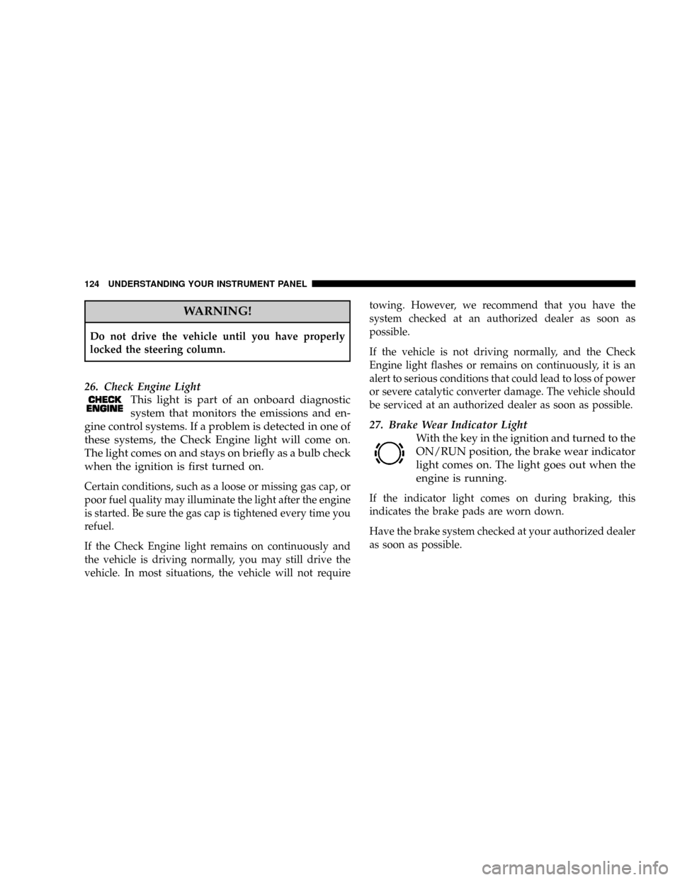
26. Check Engine Light
This light is part of an onboard diagnostic
system that monitors the emissions and en-
gine control systems. If a problem is detected in one of
these systems, the Check Engine light will come on.
The light comes on and stays on briefly as a bulb check
when the ignition is first turned on.
Certain conditions, such as a loose or missing gas cap, or
poor fuel quality may illuminate the light after the engine
is started. Be sure the gas cap is tightened every time you
refuel.
If the Check Engine light remains on continuously and
the vehicle is driving normally, you may still drive the
vehicle. In most situations, the vehicle will not requiretowing. However, we recommend that you have the
system checked at an authorized dealer as soon as
possible.
If the vehicle is not driving normally, and the Check
Engine light flashes or remains on continuously, it is an
alert to serious conditions that could lead to loss of power
or severe catalytic converter damage. The vehicle should
be serviced at an authorized dealer as soon as possible.
27. Brake Wear Indicator Light
With the key in the ignition and turned to the
ON/RUN position, the brake wear indicator
light comes on. The light goes out when the
engine is running.
If the indicator light comes on during braking, this
indicates the brake pads are worn down.
Have the brake system checked at your authorized dealer
as soon as possible.
124 UNDERSTANDING YOUR INSTRUMENT PANEL
Page 125 of 299

28. Oil Level Indicator Light
With the key in the ignition switch turned to
the ON/RUN position, the oil level indicator
light comes on. It should go out immediately
when the engine is running. If the light does
not go out, or comes on while driving, the engine oil
level has dropped to approximately the minimum
mark on the dipstick.
CHECKING ENGINE OIL LEVEL
A sensor in the oil pan allows oil level to be checked
without opening the hood. It provides an accurate mea-
surement of oil level, whereas the low engine oil level
indicator warns that oil level is definitely too low. With
the vehicle parked on a level surface, the engine is
warmed up and shut off for approximately five minutes.
When the ignition switch is turned to the ON/RUN
position, press the knob to the left of the speedometer
once and wait 7 seconds. An ISO oil level icon appears in
the trip odometer window and a ªclockº icon in the
cumulative odometer display. Pressing the knob to the
left of the speedometer twice within one second displays
one of the following messages:²OK
²-1.0 Q (-1.0L)
²-1.5 Q (-1.5L)
²-2.0 Q (-2.0L)
²HI
The indicated amount of oil must be added to the engine
if the message -2.0 Q (-2.0L) blinks and a signal sounds.
The HI message indicates that the excess oil must be
removed from the pan to avoid possible engine or
catalytic converter damage. If the ISO oil level icon and
ªclockº icon remain on when attempting to check oil
level and no message follows, or if the low engine oil
level warning lamp comes on, a malfunction in the
engine oil level system is indicated. A conveniently
located dipstick allows manual checking of the oil level.
If no leaks are noted, continue to drive to the nearest
service station where the engine oil should be topped to
the ªfullº mark on the dipstick with an approved oil.
29. Low Fuel Warning Light
When the fuel level drops to about 2 gallons (7.5
liters), this symbol will light and remains lit until
fuel is added.
UNDERSTANDING YOUR INSTRUMENT PANEL 125
4
Page 129 of 299

currently available PTY by turning the right rotary
control/push button and the program type scan search
begins.
Press the button again to keep the received program. If
the selected station does not transmit a PTY identifica-
tion, the display will show NO PTY. If all criteria for
evaluating RDS are not met, the unit will only display the
frequency.
The following are examples of program types displayed:
²NEWS ± News Service
²SOFT ± Soft Music
²INFORM ± Information Programs
²NOSTALGA ± Nostalgia
²SPORTS ± Sports Reports
²JAZZ ± Jazz Music
²TALK ± Talk Programs
²CLASSICL ± Classical
²ROCK ± Rock Music
²RB±R&B
²CLS ROCK ± Classic Rock
²SOFTRB±Soft R&B
²ADLT HIT ± Adult Hits
²LANGUAGE ± Language Program
²SOFT RCK ± Soft Rock
²REL MUSC ± Religious Music
²TOP 40 ± Top 40
²REL TALK ± Religious Talk
²COUNTRY ± Country Music
²PERSNLTY ± Personality
²OLDIES ± Oldies Format
²PUBLIC ± Public Radio
²WEATHER ± Weather Forecast
²PTY 24-28 ± Not Specified
²NO PTY ± No Program Type
UNDERSTANDING YOUR INSTRUMENT PANEL 129
4
Page 131 of 299

CAUTION!
Before inserting a CD, assure that a CD is not already
in the player. Press the CD button; if the display
shows NO CDS, a new CD can be inserted. If a CD is
already loaded, press and release the EJT button and
allow time for the current CD to be ejected. Loading
a new CD into the player while another CD is already
loaded can result in a jammed mechanism which may
require service at an authorized dealer.
Insert the CD into the slot with the printed side up. The
unit will display the number of tracks and total playback
time. After the last track has been played back, the unit
automatically begins to play the first track again.
To eject a disc, briefly press and release the
EJT button.
If the power is turned off, the disc will remain in the CD
slot for protection.Features of the CD player:²Skipping Tracks
Turn the right rotary control/push button. Turn fur-
ther to the left or right to skip multiple tracks. If a track
was played for less than eight seconds, the system will
skip to the next track.
²Scan Tracks (SC)
Push the right rotary control/push button until the
display shows SC. All tracks are played back for eight
seconds each. Press the button again to cancel this
feature.
²Fast Forward/Rewind (<<, >>)
Press and hold the multifunction button >> for audible
fast forward play. Press and hold the multifunction
button << for audible fast rewind play. The relative
time is displayed during this operation and continues
for an additional eight seconds after releasing the
function button.
UNDERSTANDING YOUR INSTRUMENT PANEL 131
4
Page 156 of 299

Have the transmission checked at your authorized dealer
as soon as possible.
PARKING BRAKE
When you apply the parking brake with engine
running, the brake system warning light in the
instrument cluster will come on.
NOTE:This light, when illuminated with parking brake
application, shows only that the parking brake is on. It
does not show the degree of brake application.
NOTE:If the light remains on with the parking brake
released, a brake system malfunction is indicated. Have
the brake system serviced by an authorized dealer im-
mediately.
Before leaving the vehicle, make sure that the parking
brake is fully applied. For manual transmission vehicles,
place the gear selector in REVERSE. For vehicles
equipped with automatic transmissions, place the gear
selector in the PARK position.To release the parking brake, slightly pull up the handle
while pushing the lock button, and guide the lever
downward to its stop. The brake warning light in the
instrument cluster should go out.
A warning sounds if you start to drive without having
released the parking brake.
When parking on a hill, you must set the parking brake
beforeplacing the gear selector in PARK. If you don't, the
load on the transmission locking mechanism may make it
difficult to move the selector out of PARK. As an added
156 STARTING AND OPERATING
Page 161 of 299

Synchronizing ESP
If the power supply was interrupted (battery discon-
nected or discharged), the BAS/ESP malfunction indica-
tor light may be illuminated with the engine running. To
re-synchronize the ESP, and cancel the malfunction indi-
cator light, the steering angle sensor will need to be
recalibrated.
1. Turn the ignition switch to the ON/RUN position.
2. Rotate the steering wheel to the center position.
3. Rotate the steering wheel completely to the left, and
then rotate the steering wheel completely to the right.
4. Bring the steering wheel back to the center position.
5. The BAS/ESP malfunction indicator light will go out.
If the BAS/ESP malfunction indicator light is still illumi-
nated, the vehicle should be serviced at an authorized
dealer.
ESP Control switch
The ESP control switch is located in the center console.
When the ESP is switched off, the warning light in the
instrument cluster comes on. When the ESP is switched
on, the warning light goes out.
To improve the vehicle's traction when driving with
snow chains, or starting off in deep snow, sand, or gravel,
switch off the ESP by pressing the upper half of the ESP
switch. The ESP warning light will then be continuously
STARTING AND OPERATING 161
5
Page 166 of 299

Brake Pad Break-In
The brakes on your vehicle do not require a long break-in
period, but avoid repeated hard brake applications from
high speeds during initial break-in. Also avoid severe
brake loading such as may be encountered when de-
scending long mountain grades.
POWER STEERING
The standard power steering system will give you good
vehicle response and increased ease of maneuverability
in tight spaces. The system will provide mechanical
steering capability if power assist is lost.
If for some reason, the power assist is interrupted, it will
still be possible to steer your vehicle. Under these condi-
tions you will observe a substantial increase in steering
effort, especially at very low vehicle speeds and during
parking maneuvers.
NOTE:Increased noise levels at the end of the steering
wheel travel are considered normal and does not indicate
that there is a problem with the power steering system.
Upon initial start-up in cold weather, the power
steering pump may make noise for a short period of
time. This is due to the cold, thick fluid in the steering
system. This noise should be considered normal, and
does not in any way damage the steering system.
WARNING!
Continued operation with reduced power steering
assist could pose a safety risk to yourself and others.
Service should be obtained as soon as possible.
CAUTION!
Prolong operation of the steering system at the end of
the steering wheel travel will increase the steering
fluid temperature and should be avoided when pos-
sible. Damage to the power steering pump may occur.
166 STARTING AND OPERATING
Page 169 of 299

Service Description:
95= Load Index
ÐA numerical code associated with the maximum load a tire can carry.
H= Speed Symbol
ÐA symbol indicating the range of speeds at which a tire can carry a load corresponding to its load
index under certain operating conditions.
ÐThe maximum speed corresponding to the Speed Symbol should only be achieved under specified
operating conditions. i.e. tire pressure, vehicle loading, road conditions and posted speed limits.)
Load Identification:
(...blank...(= Absence of any text on sidewall of the tire indicates a Standard Load (SL) Tire
Extra Load (XL)= Extra Load (or Reinforced) Tire
Light Load= Light Load Tire
C,D,E= Load range associated with the maximum load a tire can carry at a specified pressure
Maximum LoadÐ Maximum Load indicates the maximum load this tire is designed to carry.
Maximum PressureÐ Maximum Pressure indicates the maximum permissible cold tire inflation pressure for this
tire.
STARTING AND OPERATING 169
5