wheel torque CHRYSLER PACIFICA 2018 Owners Manual
[x] Cancel search | Manufacturer: CHRYSLER, Model Year: 2018, Model line: PACIFICA, Model: CHRYSLER PACIFICA 2018Pages: 696, PDF Size: 8.48 MB
Page 217 of 696
WARNING!(Continued)
•The capabilities of an ABS equipped vehicle must
never be exploited in a reckless or dangerous manner
that could jeopardize the user ’s safety or the safety of
others.
ABS is designed to function with the OEM tires. Modifica-
tion may result in degraded ABS performance.
Anti-Lock Brake Warning Light
The yellow “Anti-Lock Brake Warning Light” will turn on
when the ignition is turned to the ON/RUN mode and
may stay on for as long as four seconds.
If the “Anti-Lock Brake Warning Light” remains on or
comes on while driving, it indicates that the anti-lock
portion of the brake system is not functioning and that
service is required. However, the conventional brake sys-
tem will continue to operate normally if the “Anti-Lock
Brake Warning Light” is on.
If the “Anti-Lock Brake Warning Light” is on, the brake
system should be serviced as soon as possible to restore the
benefits of anti-lock brakes. If the “Anti-Lock Brake Warning
Light” does not come on when the ignition is turned to the
ON/RUN mode, have the light repaired as soon as possible.
Electronic Brake Control System
Your vehicle is equipped with an advanced Electronic
Brake Control system (EBC). This system includes Elec-
tronic Brake Force Distribution (EBD), Anti-Lock Brake
System (ABS), Brake Assist System (BAS), Hill Start Assist
(HSA), Traction Control System (TCS), Electronic Stability
Control (ESC), and Electronic Roll Mitigation (ERM). These
systems work together to enhance both vehicle stability
and control in various driving conditions.
Your vehicle may also be equipped with Ready Alert
Braking (RAB), Rain Brake Support (RBS), Trailer Sway
Control (TSC), and Dynamic Steering Torque (DST).
Traction Control System (TCS)
This system monitors the amount of wheel spin of each of
the driven wheels. If wheel spin is detected, the TCS may
apply brake pressure to the spinning wheel(s) and/or
reduce vehicle power to provide enhanced acceleration
and stability. A feature of the TCS, Brake Limited Differen-
tial (BLD), functions similar to a limited slip differential
and controls the wheel spin across a driven axle. If one
wheel on a driven axle is spinning faster than the other, the
system will apply the brake of the spinning wheel. This
5
SAFETY 215
Page 218 of 696
will allow more vehicle torque to be applied to the wheel
that is not spinning. BLD may remain enabled even if TCS
and ESC are in a reduced mode.
Brake Assist System (BAS)
The BAS is designed to optimize the vehicle’s braking
capability during emergency braking maneuvers. The sys-
tem detects an emergency braking situation by sensing the
rate and amount of brake application and then applies
optimum pressure to the brakes. This can help reduce
braking distances. The BAS complements the anti-lock
brake system (ABS). Applying the brakes very quickly
results in the best BAS assistance. To receive the benefit of
the system, you must apply continuous braking pressure
during the stopping sequence, (do not “pump” the brakes).
Do not reduce brake pedal pressure unless braking is no
longer desired. Once the brake pedal is released, the BAS is
deactivated.
WARNING!
The Brake Assist System (BAS) cannot prevent the
natural laws of physics from acting on the vehicle, nor
can it increase the traction afforded by prevailing road
(Continued)
WARNING!(Continued)
conditions. BAS cannot prevent collisions, including
those resulting from excessive speed in turns, driving
on very slippery surfaces, or hydroplaning. The capa-
bilities of a BAS-equipped vehicle must never be
exploited in a reckless or dangerous manner, which
could jeopardize the user’s safety or the safety of
others.
Brake System Warning Light
The red “Brake System Warning Light” will turn on when
the ignition is turned to the ON/RUN mode and may stay
on for as long as four seconds.
If the “Brake System Warning Light” remains on or comes
on while driving, it indicates that the brake system is not
functioning properly and that immediate service is re-
quired. If the “Brake System Warning Light” does not come
on when the ignition is turned to the ON/RUN mode, have
the light repaired as soon as possible.
Dynamic Steering Torque (DST)
Dynamic Steering Torque is a feature of the ESC and
Electric Power Steering (EPS) modules that provides
torque at the steering wheel for certain driving conditions
216 SAFETY
Page 219 of 696
in which the ESC module is detecting vehicle instability.
The torque that the steering wheel receives is only meant to
help the driver realize optimal steering behavior in order to
reach/maintain vehicle stability. The only notification the
driver receives that the feature is active is the torque
applied to the steering wheel.
NOTE:The DST feature is only meant to help the driver
realize the correct course of action through small torques
on the steering wheel, which means the effectiveness of the
DST feature is highly dependent on the driver ’s sensitivity
and overall reaction to the applied torque. It is very
important to realize that this feature will not steer the
vehicle, meaning the driver is still responsible for steering
the vehicle.
Electronic Brake Force Distribution (EBD)
This function manages the distribution of the braking
torque between the front and rear axles by limiting braking
pressure to the rear axle. This is done to prevent overslip of
the rear wheels to avoid vehicle instability, and to prevent
the rear axle from entering ABS before the front axle.
Electronic Roll Mitigation (ERM)
This system anticipates the potential for wheel lift by
monitoring the driver ’s steering wheel input and the speed
of the vehicle. When ERM determines that the rate of
change of the steering wheel angle and vehicle’s speed are
sufficient to potentially cause wheel lift, it then applies the
appropriate brake and may also reduce engine power to
lessen the chance that wheel lift will occur. ERM can only
reduce the chance of wheel lift occurring during severe or
evasive driving maneuvers; it cannot prevent wheel lift
due to other factors, such as road conditions, leaving the
roadway, or striking objects or other vehicles.
WARNING!
Many factors, such as vehicle loading, road conditions
and driving conditions, influence the chance that
wheel lift or rollover may occur. ERM cannot prevent
all wheel lift or roll overs, especially those that involve
leaving the roadway or striking objects or other ve-
hicles. The capabilities of an ERM-equipped vehicle
must never be exploited in a reckless or dangerous
manner which could jeopardize the user’s safety or the
safety of others.
5
SAFETY 217
Page 396 of 696
CAUTION!
•The ParkSense Active Park Assist system is only a
parking aid and it is unable to recognize every
obstacle, including small obstacles. Parking curbs
might be temporarily detected or not detected at all.
Obstacles located above or below the sensors will
not be detected when they are in close proximity.
• The vehicle must be driven slowly when using the
ParkSense Active Park Assist system in order to be
able to stop in time when an obstacle is detected. It is
recommended that the driver looks over his/her
shoulder when using the ParkSense Active Park
Assist system.
LANESENSE — IF EQUIPPED
LaneSense Operation
The LaneSense system is operational at speeds above
37 mph (60 km/h) and below 112 mph (180 km/h). It uses
a forward looking camera to detect lane markings and
measure vehicle position within the lane boundaries.
When both lane markings are detected and the driver
unintentionally drifts out of the lane (no turn signal
applied), the LaneSense system provides a haptic warning in the form of torque applied to the steering wheel to
prompt the driver to remain within the lane boundaries.
The LaneSense system will also provide a visual warning
through the instrument cluster display to prompt the
driver to remain within the lane boundaries.
The driver may manually override the haptic warning by
applying torque into the steering wheel at any time.
When only a single lane marking is detected and the driver
unintentionally drifts across that lane marking (no turn
signal applied), the LaneSense system provides a visual
warning through the instrument cluster display to prompt
the driver to remain within the lane. When only a single
lane marking is detected, a haptic (torque) warning will not
be provided.
NOTE:
When operating conditions have been met, the
LaneSense system will monitor if the driver ’s hands are on
the steering wheel and provides an audible and visual
warning to the driver when the driver ’s hands are not
detected on the steering wheel. The system will cancel if
the driver does not return their hands to the wheel.
394 STARTING AND OPERATING
Page 399 of 696
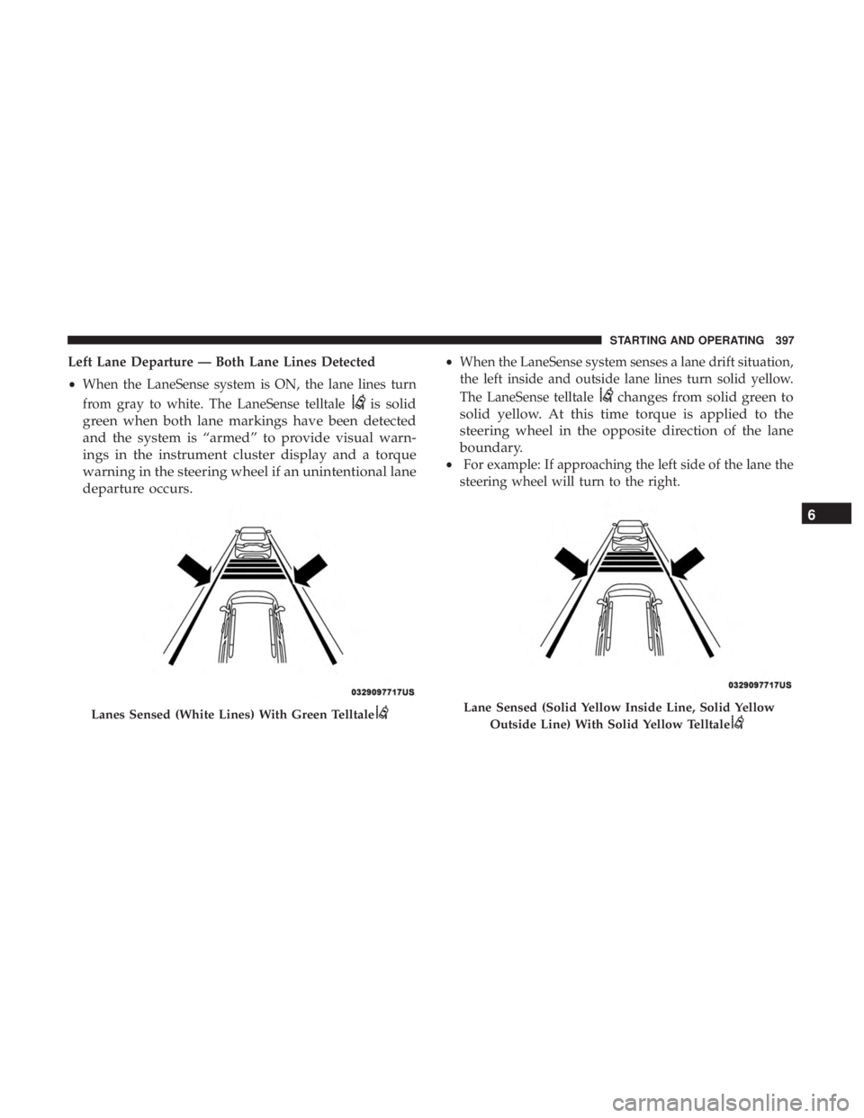
Left Lane Departure — Both Lane Lines Detected
•When the LaneSense system is ON, the lane lines turn
from gray to white. The LaneSense telltale
is solid
green when both lane markings have been detected
and the system is “armed” to provide visual warn-
ings in the instrument cluster display and a torque
warning in the steering wheel if an unintentional lane
departure occurs.
• When the LaneSense system senses a lane drift situation,
the left inside and outside lane lines turn solid yellow.
The LaneSense telltale
changes from solid green to
solid yellow. At this time torque is applied to the
steering wheel in the opposite direction of the lane
boundary.
• For example: If approaching the left side of the lane the
steering wheel will turn to the right.
Lanes Sensed (White Lines) With Green TelltaleLane Sensed (Solid Yellow Inside Line, Solid Yellow
Outside Line) With Solid Yellow Telltale
6
STARTING AND OPERATING 397
Page 400 of 696
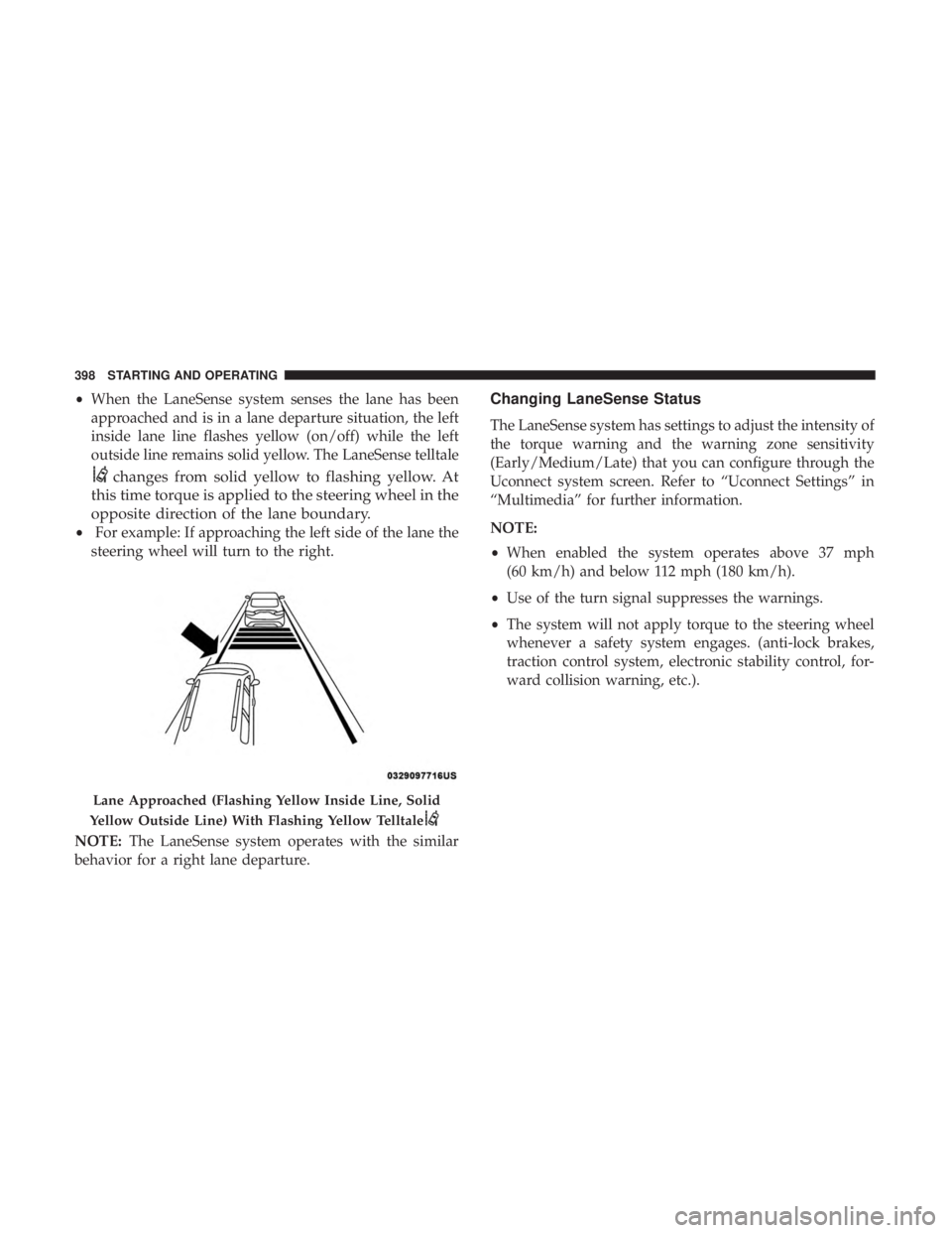
•When the LaneSense system senses the lane has been
approached and is in a lane departure situation, the left
inside lane line flashes yellow (on/off) while the left
outside line remains solid yellow. The LaneSense telltale
changes from solid yellow to flashing yellow. At
this time torque is applied to the steering wheel in the
opposite direction of the lane boundary.
• For example: If approaching the left side of the lane the
steering wheel will turn to the right.
NOTE: The LaneSense system operates with the similar
behavior for a right lane departure.
Changing LaneSense Status
The LaneSense system has settings to adjust the intensity of
the torque warning and the warning zone sensitivity
(Early/Medium/Late) that you can configure through the
Uconnect system screen. Refer to “Uconnect Settings” in
“Multimedia” for further information.
NOTE:
• When enabled the system operates above 37 mph
(60 km/h) and below 112 mph (180 km/h).
• Use of the turn signal suppresses the warnings.
• The system will not apply torque to the steering wheel
whenever a safety system engages. (anti-lock brakes,
traction control system, electronic stability control, for-
ward collision warning, etc.).
Lane Approached (Flashing Yellow Inside Line, Solid
Yellow Outside Line) With Flashing Yellow Telltale
398 STARTING AND OPERATING
Page 455 of 696
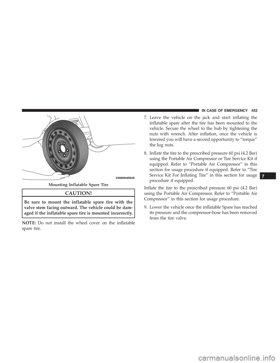
CAUTION!
Be sure to mount the inflatable spare tire with the
valve stem facing outward. The vehicle could be dam-
aged if the inflatable spare tire is mounted incorrectly.
NOTE: Do not install the wheel cover on the inflatable
spare tire. 7. Leave the vehicle on the jack and start inflating the
inflatable spare after the tire has been mounted to the
vehicle. Secure the wheel to the hub by tightening the
nuts with wrench. After inflation, once the vehicle is
lowered you will have a second opportunity to “torque”
the lug nuts.
8. Inflate the tire to the prescribed pressure 60 psi (4.2 Bar) using the Portable Air Compressor or Tire Service Kit if
equipped. Refer to “Portable Air Compressor” in this
section for usage procedure if equipped. Refer to “Tire
Service Kit For Inflating Tire” in this section for usage
procedure if equipped.
Inflate the tire to the prescribed pressure 60 psi (4.2 Bar)
using the Portable Air Compressor. Refer to “Portable Air
Compressor” in this section for usage procedure.
9. Lower the vehicle once the inflatable Spare has reached its pressure and the compressor-hose has been removed
from the tire valve.
Mounting Inflatable Spare Tire
7
IN CASE OF EMERGENCY 453
Page 456 of 696
10. Finish tightening the lug nuts. Push down on thewrench while at the end of the handle for increased
leverage. Tighten the lug nuts in a star pattern until
each nut has been tightened twice. Refer to “Torque
Specifications” in “Technical Specifications” for proper
wheel lug nut torque. If in doubt about the correct
tightness, have them checked with a torque wrench by
your authorized dealer or at a service station.
11. Lower the jack to its fully-closed position.
WARNING!
A loose tire or jack thrown forward in a collision or
hard stop could endanger the occupants of the vehicle.
Always stow the jack parts and the spare tire in the
places provided. Have the deflated (flat) tire repaired
or replaced immediately.
12. Place the deflated (flat) tire and foam tray cover assembly in the rear cargo area. Do not stow the
deflated tire in the inflatable spare tire location. Have
the full-sized tire repaired or replaced, as soon as
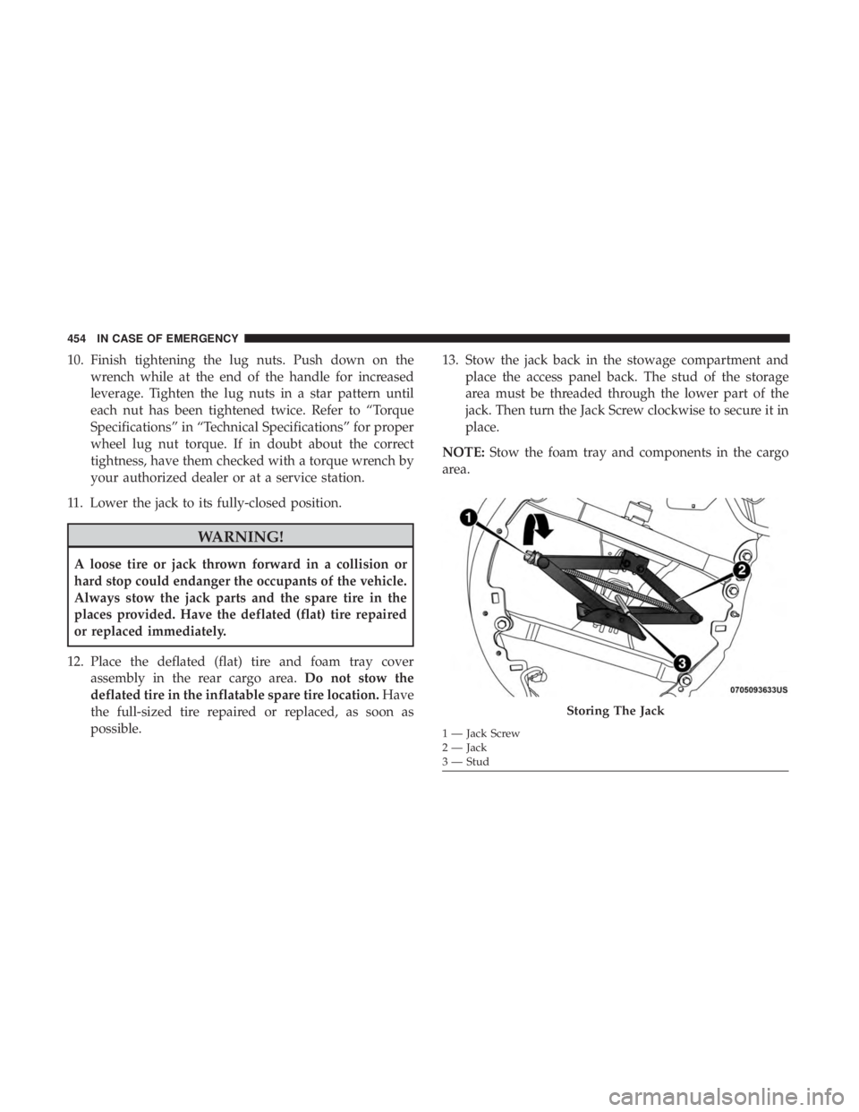
possible. 13. Stow the jack back in the stowage compartment and
place the access panel back. The stud of the storage
area must be threaded through the lower part of the
jack. Then turn the Jack Screw clockwise to secure it in
place.
NOTE: Stow the foam tray and components in the cargo
area.
Storing The Jack
1 — Jack Screw
2 — Jack
3 — Stud
454 IN CASE OF EMERGENCY
Page 457 of 696
Road Tire Installation
Vehicles Equipped With Wheel Covers
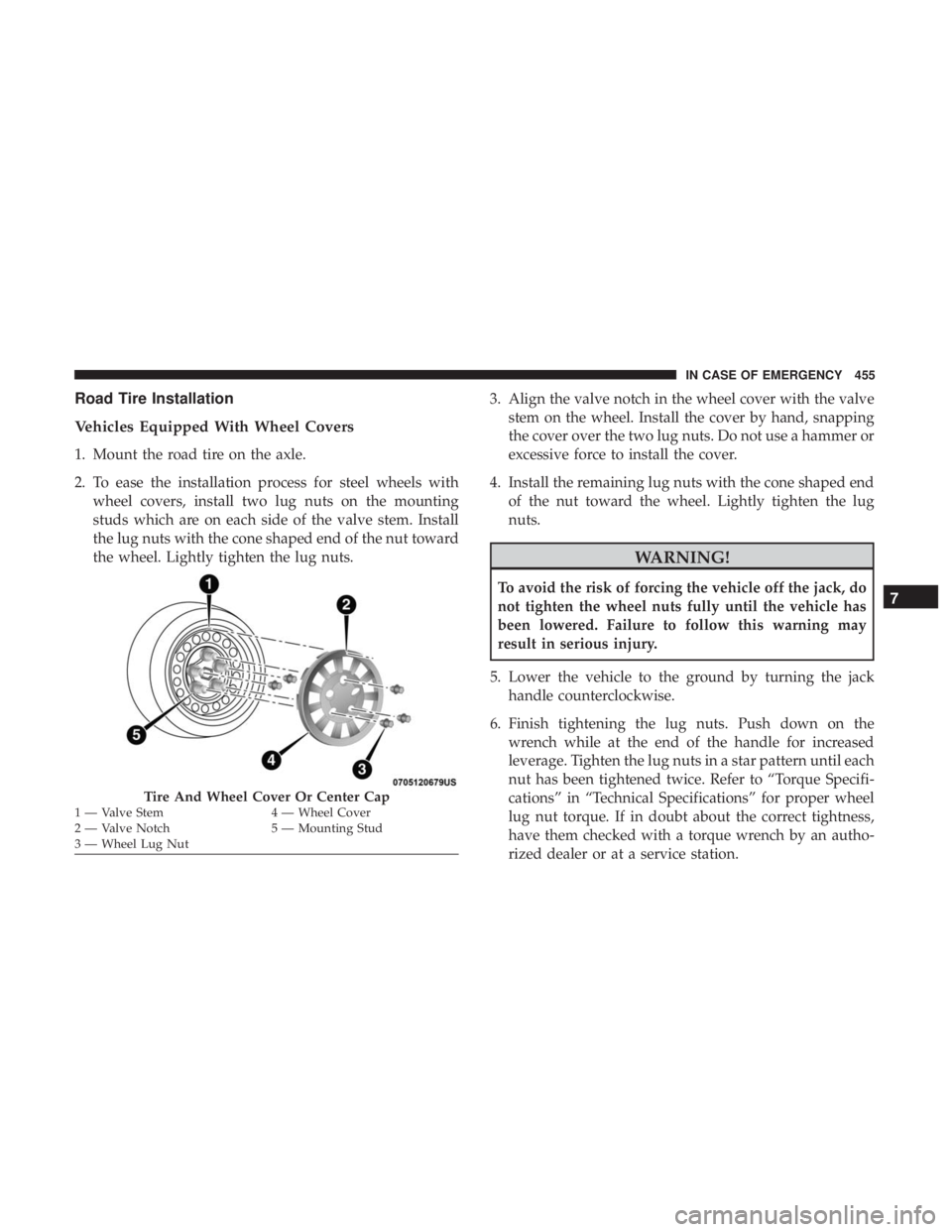
1. Mount the road tire on the axle.
2. To ease the installation process for steel wheels withwheel covers, install two lug nuts on the mounting
studs which are on each side of the valve stem. Install
the lug nuts with the cone shaped end of the nut toward
the wheel. Lightly tighten the lug nuts. 3. Align the valve notch in the wheel cover with the valve
stem on the wheel. Install the cover by hand, snapping
the cover over the two lug nuts. Do not use a hammer or
excessive force to install the cover.
4. Install the remaining lug nuts with the cone shaped end of the nut toward the wheel. Lightly tighten the lug
nuts.
WARNING!
To avoid the risk of forcing the vehicle off the jack, do
not tighten the wheel nuts fully until the vehicle has
been lowered. Failure to follow this warning may
result in serious injury.
5. Lower the vehicle to the ground by turning the jack handle counterclockwise.
6. Finish tightening the lug nuts. Push down on the wrench while at the end of the handle for increased
leverage. Tighten the lug nuts in a star pattern until each
nut has been tightened twice. Refer to “Torque Specifi-
cations” in “Technical Specifications” for proper wheel
lug nut torque. If in doubt about the correct tightness,
have them checked with a torque wrench by an autho-
rized dealer or at a service station.
Tire And Wheel Cover Or Center Cap1 — Valve Stem 4 — Wheel Cover
2 — Valve Notch 5 — Mounting Stud
3 — Wheel Lug Nut
7
IN CASE OF EMERGENCY 455
Page 458 of 696
7. After 25 miles (40 km) check the lug nut torque with atorque wrench to ensure that all lug nuts are properly
seated against the wheel.
Vehicles Without Wheel Covers
1. Mount the road tire on the axle.
2. Install the remaining lug nuts with the cone shaped endof the nut toward the wheel. Lightly tighten the lug
nuts.
WARNING!
To avoid the risk of forcing the vehicle off the jack, do
not tighten the wheel nuts fully until the vehicle has
been lowered. Failure to follow this warning may
result in serious injury. 3. Lower the vehicle to the ground by turning the jack
handle counterclockwise.
4. Finish tightening the lug nuts. Push down on the wrench while at the end of the handle for increased
leverage. Tighten the lug nuts in a star pattern until each
nut has been tightened twice. Refer to “Torque Specifi-
cations” in the “Technical Specifications” section for
proper wheel lug nut torque. If in doubt about the
correct tightness, have them checked with a torque
wrench by your authorized dealer or at a service station.
5. After 25 miles (40 km) check the lug nut torque with a torque wrench to ensure that all lug nuts are properly
seated against the wheel.
456 IN CASE OF EMERGENCY