Power outlet CHRYSLER PACIFICA 2019 User Guide
[x] Cancel search | Manufacturer: CHRYSLER, Model Year: 2019, Model line: PACIFICA, Model: CHRYSLER PACIFICA 2019Pages: 718, PDF Size: 8.6 MB
Page 492 of 718
NOTE:Sealant may leak out through the puncture in the
tire.
If the sealant (white fluid) does not flow within0–10
seconds through the Sealant Hose:
1. Push the Power Button to turn the Tire Service Kit off. Disconnect the Sealant Hose from the valve stem. Make
sure the valve stem is free of debris. Reconnect the
Sealant Hose to the valve stem. Check that the Mode
Select Knob is in the Sealant Mode position and not Air
Mode. Push the Power Button to turn the Tire Service
Kit on.
2. Connect the Power Plug to a different 12 Volt power outlet in your vehicle or another vehicle, if available.
Make sure the vehicle is running before turning the Tire
Service Kit on.
3. The Sealant Bottle may be empty due to previous use. Call for assistance. If the sealant (white fluid) does flow through the Sealant
Hose:
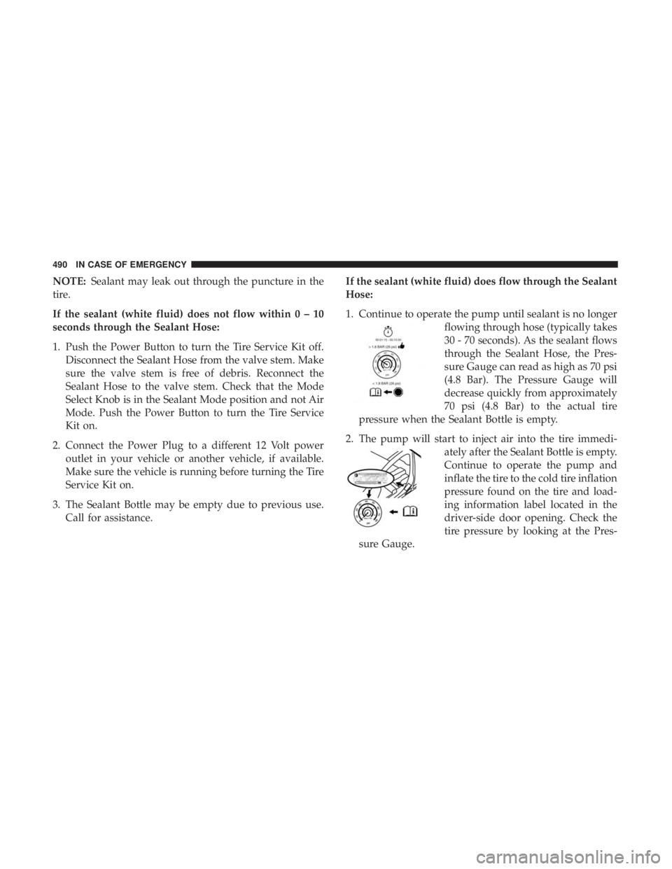
1. Continue to operate the pump until sealant is no longer
flowing through hose (typically takes
30 - 70 seconds). As the sealant flows
through the Sealant Hose, the Pres-
sure Gauge can read as high as 70 psi
(4.8 Bar). The Pressure Gauge will
decrease quickly from approximately
70 psi (4.8 Bar) to the actual tire
pressure when the Sealant Bottle is empty.
2. The pump will start to inject air into the tire immedi- ately after the Sealant Bottle is empty.
Continue to operate the pump and
inflate the tire to the cold tire inflation
pressure found on the tire and load-
ing information label located in the
driver-side door opening. Check the
tire pressure by looking at the Pres-
sure Gauge.
490 IN CASE OF EMERGENCY
Page 494 of 718
After Driving:
Pull over to a safe location. Refer to “Whenever You Stop
To Use Tire Service Kit” in this section before continuing.
1. Uncoil the Sealant Hose, and then remove the cap fromthe fitting at the end of the hose.
2. Place the Tire Service Kit flat on the ground next to the deflated tire.
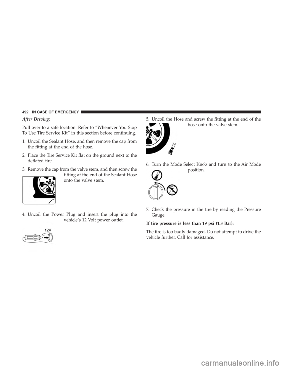
3. Remove the cap from the valve stem, and then screw the fitting at the end of the Sealant Hose
onto the valve stem.
4. Uncoil the Power Plug and insert the plug into the vehicle’s 12 Volt power outlet. 5. Uncoil the Hose and screw the fitting at the end of the
hose onto the valve stem.
6. Turn the Mode Select Knob and turn to the Air Mode position.
7. Check the pressure in the tire by reading the Pressure Gauge.
If tire pressure is less than 19 psi (1.3 Bar):
The tire is too badly damaged. Do not attempt to drive the
vehicle further. Call for assistance.
492 IN CASE OF EMERGENCY
Page 495 of 718
If the tire pressure is 19 psi (1.3 Bar) or higher:
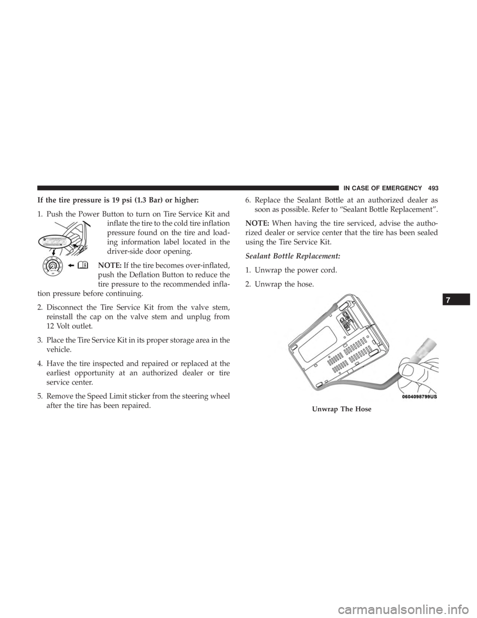
1. Push the Power Button to turn on Tire Service Kit andinflate the tire to the cold tire inflation
pressure found on the tire and load-
ing information label located in the
driver-side door opening.
NOTE: If the tire becomes over-inflated,
push the Deflation Button to reduce the
tire pressure to the recommended infla-
tion pressure before continuing.
2. Disconnect the Tire Service Kit from the valve stem, reinstall the cap on the valve stem and unplug from
12 Volt outlet.
3. Place the Tire Service Kit in its proper storage area in the vehicle.
4. Have the tire inspected and repaired or replaced at the earliest opportunity at an authorized dealer or tire
service center.
5. Remove the Speed Limit sticker from the steering wheel after the tire has been repaired. 6. Replace the Sealant Bottle at an authorized dealer as
soon as possible. Refer to “Sealant Bottle Replacement”.
NOTE: When having the tire serviced, advise the autho-
rized dealer or service center that the tire has been sealed
using the Tire Service Kit.
Sealant Bottle Replacement:
1. Unwrap the power cord.
2. Unwrap the hose.
Unwrap The Hose
7
IN CASE OF EMERGENCY 493
Page 500 of 718
4. Connect the opposite end of the negative(-)jumper
cable to the negative post near the windshield cowl
(exposed metal part of the discharged vehicle’s engine).
WARNING!
Do not connect the jumper cable to the negative (-) post
of the discharged battery. The resulting electrical spark
could cause the battery to explode and could result in
personal injury. Only use the specific ground point, do
not use any other exposed metal parts.
5. Start the engine in the vehicle that has the booster battery, let the engine idle a few minutes, and then start
the engine in the vehicle with the discharged battery.
6. Once the engine is started, remove the jumper cables in the reverse sequence:
Disconnecting The Jumper Cables
1. Disconnect the negative (-)end of the jumper cable from
the engine ground of the vehicle with the discharged
battery.
2. Disconnect the opposite end of the negative (-)jumper
cable from the negative (-)post of the booster battery. 3. Disconnect the positive
(+)end of the jumper cable from
the positive (+)post of the booster battery.
4. Disconnect the opposite end of the positive (+)jumper
cable from the positive (+)post of the vehicle with the
discharged battery.
If frequent jump starting is required to start your vehicle
you should have the battery and charging system in-
spected at an authorized dealer.
CAUTION!
Accessories plugged into the vehicle power outlets
draw power from the vehicle’s battery, even when not
in use (i.e., cellular devices, etc.). Eventually, if plugged
in long enough without engine operation, the vehicle’s
battery will discharge sufficiently to degrade battery
life and/or prevent the engine from starting.
498 IN CASE OF EMERGENCY
Page 607 of 718
Setting NameSelectable Options
NOTE:
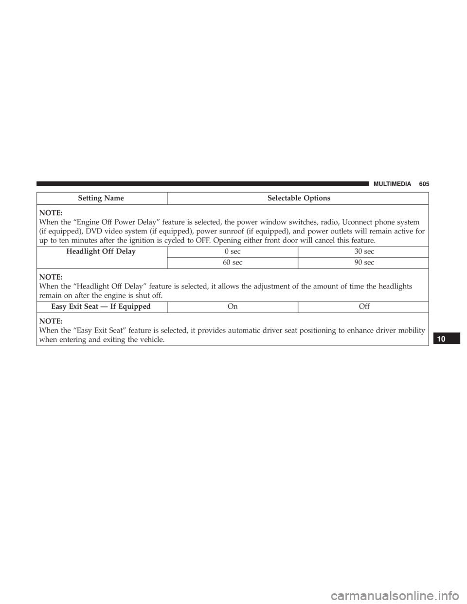
When the “Engine Off Power Delay” feature is selected, the power window switches, radio, Uconnect phone system
(if equipped), DVD video system (if equipped), power sunroof (if equipped), and power outlets will remain active for
up to ten minutes after the ignition is cycled to OFF. Opening either front door will cancel this feature. Headlight Off Delay 0 sec30 sec
60 sec 90 sec
NOTE:
When the “Headlight Off Delay” feature is selected, it allows the adjustment of the amount of time the headlights
remain on after the engine is shut off. Easy Exit Seat — If Equipped OnOff
NOTE:
When the “Easy Exit Seat” feature is selected, it provides automatic driver seat positioning to enhance driver mobility
when entering and exiting the vehicle.
10
MULTIMEDIA 605
Page 635 of 718
Setting NameSelectable Options
NOTE:
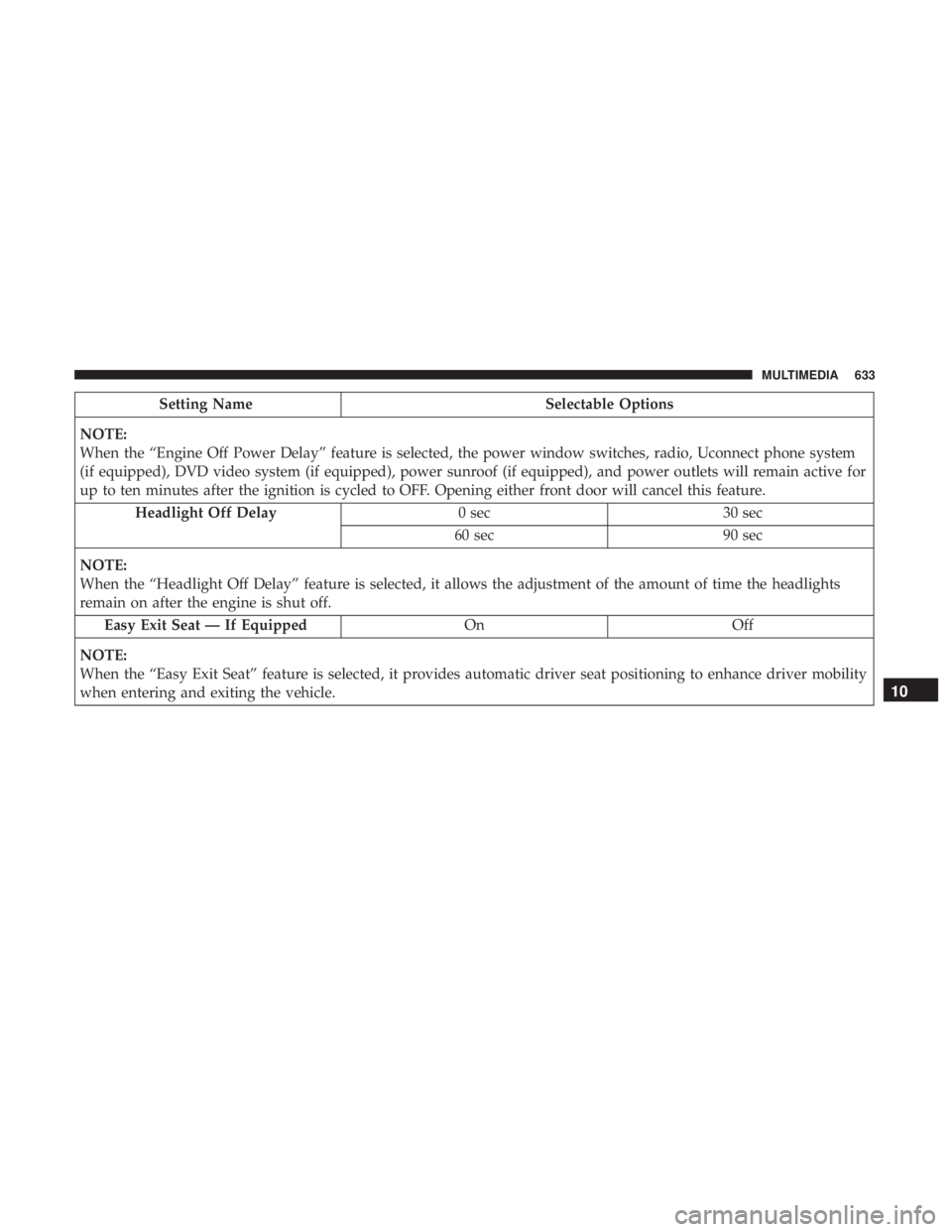
When the “Engine Off Power Delay” feature is selected, the power window switches, radio, Uconnect phone system
(if equipped), DVD video system (if equipped), power sunroof (if equipped), and power outlets will remain active for
up to ten minutes after the ignition is cycled to OFF. Opening either front door will cancel this feature. Headlight Off Delay 0 sec30 sec
60 sec 90 sec
NOTE:
When the “Headlight Off Delay” feature is selected, it allows the adjustment of the amount of time the headlights
remain on after the engine is shut off. Easy Exit Seat — If Equipped OnOff
NOTE:
When the “Easy Exit Seat” feature is selected, it provides automatic driver seat positioning to enhance driver mobility
when entering and exiting the vehicle.
10
MULTIMEDIA 633
Page 643 of 718
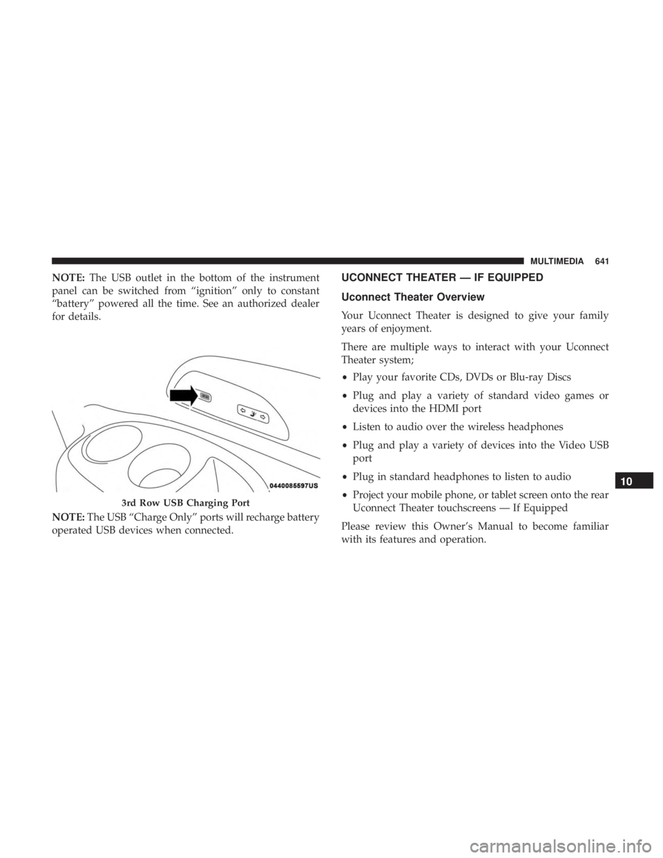
NOTE:The USB outlet in the bottom of the instrument
panel can be switched from “ignition” only to constant
“battery” powered all the time. See an authorized dealer
for details.
NOTE: The USB “Charge Only” ports will recharge battery
operated USB devices when connected.UCONNECT THEATER — IF EQUIPPED
Uconnect Theater Overview
Your Uconnect Theater is designed to give your family
years of enjoyment.
There are multiple ways to interact with your Uconnect
Theater system;
• Play your favorite CDs, DVDs or Blu-ray Discs
• Plug and play a variety of standard video games or
devices into the HDMI port
• Listen to audio over the wireless headphones
• Plug and play a variety of devices into the Video USB
port
• Plug in standard headphones to listen to audio
• Project your mobile phone, or tablet screen onto the rear
Uconnect Theater touchscreens — If Equipped
Please review this Owner’s Manual to become familiar
with its features and operation.
3rd Row USB Charging Port
10
MULTIMEDIA 641
Page 675 of 718
is no guarantee that interference will not occur in a
particular installation. If this equipment does cause harm-
ful interference to radio or television reception, which can
be determined by turning the equipment off and on, the
user is encouraged to try to correct the interference by one
or more of the following measures:
•Reorient or relocate the receiving antenna.
• Increase the separation between the equipment and
receiver.
• Connect the equipment into an outlet on a circuit
different from that to which the receiver is connected.
• Consult the dealer or an experienced radio/TV techni-
cian for help.
CAN ICES-3 (B) / NMB-3 (B)
This Class B digital apparatus complies with Canadian
ICES-003.
RADIO OPERATION AND MOBILE PHONES
Under certain conditions, the mobile phone being on in
your vehicle can cause erratic or noisy performance from
your radio. This condition may be lessened or eliminated
by relocating the mobile phone antenna. This condition is
not harmful to the radio. If your radio performance does not satisfactorily “clear” by the repositioning of the an-
tenna, it is recommended that the radio volume be turned
down or off during mobile phone operation when not
using Uconnect (if equipped).
Regulatory And Safety Information
USA/CANADA
Exposure to Radio Frequency Radiation
The radiated output power of the internal wireless radio is
far below the FCC and IC radio frequency exposure limits.
Nevertheless, the wireless radio will be used in such a
manner that the radio is 8 in (20 cm) or further from the
human body.
The internal wireless radio operates within guidelines
found in radio frequency safety standards and recommen-
dations, which reflect the consensus of the scientific com-
munity.
The radio manufacturer believes the internal wireless radio
is safe for use by consumers. The level of energy emitted is
far less than the electromagnetic energy emitted by wire-
less devices such as mobile phones. However, the use of
wireless radios may be restricted in some situations or
10
MULTIMEDIA 673
Page 703 of 718
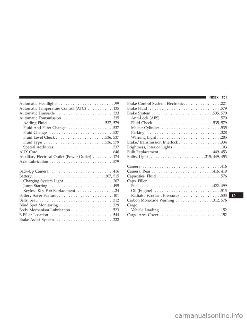
Automatic Headlights........................99
Automatic Temperature Control (ATC) ...........135
Automatic Transaxle ....................... .333
Automatic Transmission ..................... .335
Adding Fluid ....................... .537, 579
Fluid And Filter Change ...................537
Fluid Change .......................... .537
Fluid Level Check .....................536, 537
Fluid Type ......................... .536, 579
Special Additives ........................ .537
AUXCord .............................. .640
Auxiliary Electrical Outlet (Power Outlet) .........174
Axle Lubrication .......................... .579
Back-Up Camera .......................... .416
Battery .............................. .207, 515
Charging System Light ....................207
Jump Starting .......................... .495
Keyless Key Fob Replacement ................24
Battery Saver Feature ....................... .101
Belts, Seat ............................... .312
Blind Spot Monitoring ...................... .229
Body Mechanism Lubrication ..................523
B-Pillar Location .......................... .544
Brake Assist System ........................ .222Brake Control System, Electronic
................221
Brake Fluid .............................. .579
Brake System ......................... .535, 570
Anti-Lock (ABS) ........................ .570
Fluid Check ........................ .535, 579
Master Cylinder ........................ .535
Parking .............................. .328
Warning Light .......................... .205
Brake/Transmission Interlock ..................334
Brightness, Interior Lights ....................103
Bulb Replacement ...................... .449, 453
Bulbs,
Light ....................... .315, 449, 453
Camera ................................ .416
Camera, Rear ......................... .416, 419
Capacities, Fluid .......................... .576
Caps, Filler Fuel .............................. .422, 499
Oil (Engine) ........................... .513
Radiator (Coolant Pressure) .................533
Carbon Monoxide Warning ................312, 576
Cargo Vehicle Loading ......................... .152
Cargo Area Cover ......................... .152
12
INDEX 701
Page 711 of 718
ParkSense System, Rear...................368, 378
Personalized Main Menu .....................584
Pets ....................................311
Placard, Tire And Loading Information ...........544
Power Brakes ............................... .570
Inverter .............................. .177
Mirrors ................................94
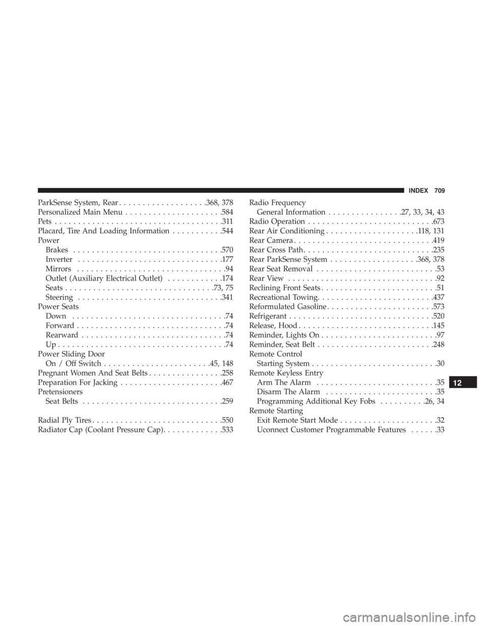
Outlet (Auxiliary Electrical Outlet) ............174
Seats ............................... .73, 75
Steering .............................. .341
Power Seats Down .................................74
Forward ................................74
Rearward ...............................74
Up....................................74
Power Sliding Door On / Off Switch ...................... .45, 148
Pregnant Women And Seat Belts ................258
Preparation For Jacking ..................... .467
Pretensioners Seat Belts ............................. .259
Radial Ply Tires ........................... .550
Radiator Cap (Coolant Pressure Cap) .............533Radio Frequency
General Information ................27, 33, 34, 43
Radio Operation .......................... .673
Rear Air Conditioning ....................118,131
Rear Camera ............................. .419
Rear Cross Path ........................... .235
Rear ParkSense System ...................368, 378
Rear Seat Removal ..........................53
Rear View ................................92
Reclining Front Seats .........................51
Recreational Towing ........................ .437
Reformulated Gasoline ...................... .573
Refrigerant .............................. .520
Release, Hood ............................ .145
Reminder, Lights On .........................97
Reminder, Seat Belt ........................ .248
Remote Control Starting System ...........................30
Remote Keyless Entry Arm
The Alarm ..........................35
Disarm The Alarm ........................35
Programming Additional Key Fobs ..........26, 34
Remote Starting Exit Remote Start Mode .....................32
Uconnect Customer Programmable Features ......33
12
INDEX 709