12 volt outlet CHRYSLER PACIFICA 2019 Owners Manual
[x] Cancel search | Manufacturer: CHRYSLER, Model Year: 2019, Model line: PACIFICA, Model: CHRYSLER PACIFICA 2019Pages: 718, PDF Size: 8.6 MB
Page 176 of 718
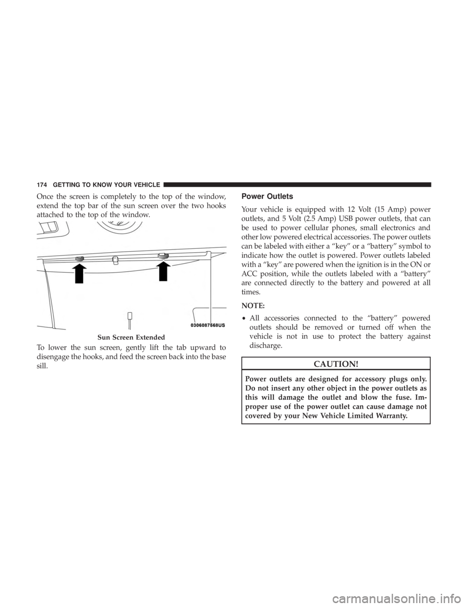
Once the screen is completely to the top of the window,
extend the top bar of the sun screen over the two hooks
attached to the top of the window.
To lower the sun screen, gently lift the tab upward to
disengage the hooks, and feed the screen back into the base
sill.Power Outlets
Your vehicle is equipped with 12 Volt (15 Amp) power
outlets, and 5 Volt (2.5 Amp) USB power outlets, that can
be used to power cellular phones, small electronics and
other low powered electrical accessories. The power outlets
can be labeled with either a “key” or a “battery” symbol to
indicate how the outlet is powered. Power outlets labeled
with a “key” are powered when the ignition is in the ON or
ACC position, while the outlets labeled with a “battery”
are connected directly to the battery and powered at all
times.
NOTE:
•All accessories connected to the “battery” powered
outlets should be removed or turned off when the
vehicle is not in use to protect the battery against
discharge.
CAUTION!
Power outlets are designed for accessory plugs only.
Do not insert any other object in the power outlets as
this will damage the outlet and blow the fuse. Im-
proper use of the power outlet can cause damage not
covered by your New Vehicle Limited Warranty.
Sun Screen Extended
174 GETTING TO KNOW YOUR VEHICLE
Page 177 of 718
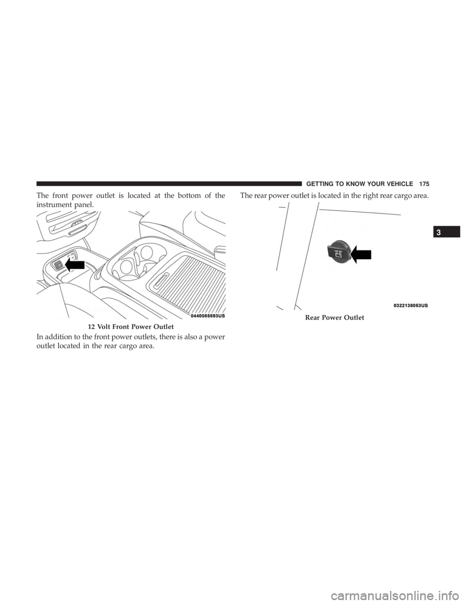
The front power outlet is located at the bottom of the
instrument panel.
In addition to the front power outlets, there is also a power
outlet located in the rear cargo area.The rear power outlet is located in the right rear cargo area.
12 Volt Front Power Outlet
Rear Power Outlet
3
GETTING TO KNOW YOUR VEHICLE 175
Page 178 of 718
WARNING!
To avoid serious injury or death:
•Only devices designed for use in this type of outlet
should be inserted into any 12 Volt outlet.
• Do not touch with wet hands.
(Continued)
WARNING! (Continued)
•Close the lid when not in use and while driving the
vehicle.
• If this outlet is mishandled, it may cause an electric
shock and failure.
CAUTION!
• Many accessories that can be plugged in draw power
from the vehicle’s battery, even when not in use (i.e.,
cellular phones, etc.). Eventually, if plugged in long
enough, the vehicle’s battery will discharge suffi-
ciently to degrade battery life and/or prevent the
engine from starting.
• Accessories that draw higher power (i.e., coolers,
vacuum cleaners, lights, etc.) will degrade the battery
even more quickly. Only use these intermittently and
with greater caution.
• After the use of high power draw accessories, or long
periods of the vehicle not being started (with acces-
sories still plugged in), the vehicle must be driven a
sufficient length of time to allow the generator to
recharge the vehicle’s battery.
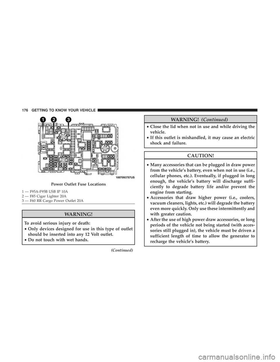
Power Outlet Fuse Locations
1 — F95A-F95B USB IP 10A
2 — F85 Cigar Lighter 20A
3 — F60 RR Cargo Power Outlet 20A 176 GETTING TO KNOW YOUR VEHICLE
Page 179 of 718
Power Inverter — If Equipped
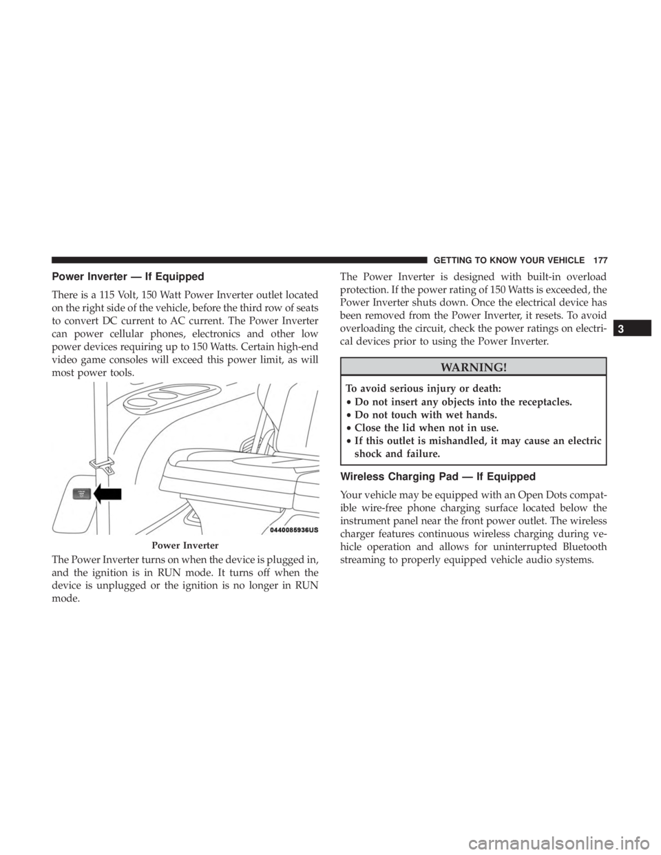
There is a 115 Volt, 150 Watt Power Inverter outlet located
on the right side of the vehicle, before the third row of seats
to convert DC current to AC current. The Power Inverter
can power cellular phones, electronics and other low
power devices requiring up to 150 Watts. Certain high-end
video game consoles will exceed this power limit, as will
most power tools.
The Power Inverter turns on when the device is plugged in,
and the ignition is in RUN mode. It turns off when the
device is unplugged or the ignition is no longer in RUN
mode.The Power Inverter is designed with built-in overload
protection. If the power rating of 150 Watts is exceeded, the
Power Inverter shuts down. Once the electrical device has
been removed from the Power Inverter, it resets. To avoid
overloading the circuit, check the power ratings on electri-
cal devices prior to using the Power Inverter.
WARNING!
To avoid serious injury or death:
•
Do not insert any objects into the receptacles.
• Do not touch with wet hands.
• Close the lid when not in use.
• If this outlet is mishandled, it may cause an electric
shock and failure.
Wireless Charging Pad — If Equipped
Your vehicle may be equipped with an Open Dots compat-
ible wire-free phone charging surface located below the
instrument panel near the front power outlet. The wireless
charger features continuous wireless charging during ve-
hicle operation and allows for uninterrupted Bluetooth
streaming to properly equipped vehicle audio systems.
Power Inverter
3
GETTING TO KNOW YOUR VEHICLE 177
Page 329 of 718
2. The ignition switch will return to the OFF position.
3. If the gear selector is not in PARK, the ENGINE START/STOP button must be held for two seconds or three short
pushes in a row with the vehicle speed above 5 mph
(8 km/h) before the engine will shut off. The ignition
switch position will remain in the ACC position until the
gear selector is in PARK and the button is pushed twice
to the OFF position. If the gear selector is not in PARK
and the ENGINE START/STOP button is pushed once,
the instrument cluster will display a “Vehicle Not In
Park” message and the engine will remain running.
Never leave a vehicle out of the PARK position, or it
could roll.
NOTE: If the ignition switch is left in the ACC or RUN
(engine not running) position and the transmission is in
PARK, the system will automatically time out after 30
minutes of inactivity and the ignition will switch to the
OFF position.
ENGINE BLOCK HEATER — IF EQUIPPED
The engine block heater warms the engine and permits
quicker starts in cold weather.
Connect the cord to a 110-115 Volt AC electrical outlet with
a grounded, three-wire extension cord. For ambient temperatures below 0°F (-18°C), the engine
block heater is recommended. For ambient temperatures
below -20°F (-29°C), the engine block heater is required.
The engine block heater cord is routed under the hood,
behind to the passenger ’s side headlamp. Follow the steps
below to properly use the engine block heater:
1. Locate the engine block heater cord (behind the passen-
ger ’s side headlamp).
2. Undo the hook-and-loop strap that secures the heater cord in place.
3. Pull the cord to the front of the vehicle and plug it into a grounded, three-wire extension cord.
4. After the vehicle is running, reattach the cord to the hook-and-loop strap and properly stow away behind
the passenger ’s side headlamp.
NOTE:
• The engine block heater cord is a factory installed
option. If your vehicle is not equipped, heater cords are
available from your authorized Mopar dealer.
• The engine block heater will require 110 Volts AC and
6.5 Amps to activate the heater element.
6
STARTING AND OPERATING 327
Page 480 of 718
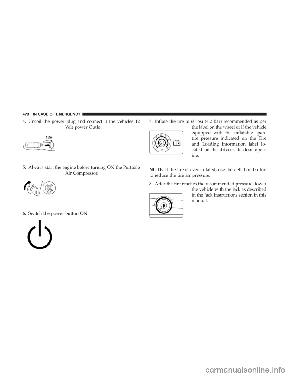
4. Uncoil the power plug and connect it the vehicles 12Volt power Outlet.
5. Always start the engine before turning ON the Portable Air Compressor.
6. Switch the power button ON. 7. Inflate the tire to 60 psi (4.2 Bar) recommended as per
the label on the wheel or if the vehicle
equipped with the inflatable spare
tire pressure indicated on the Tire
and Loading information label lo-
cated on the driver-side door open-
ing.
NOTE: If the tire is over inflated, use the deflation button
to reduce the tire air pressure.
8. After the tire reaches the recommended pressure, lower the vehicle with the jack as described
in the Jack Instructions section in this
manual.
478 IN CASE OF EMERGENCY
Page 484 of 718
Whenever You Stop To Use Tire Service Kit:
1. Pull over to a safe location and turn on the vehicle’sHazard Warning flashers.
2. Verify that the valve stem (on the wheel with the deflated tire) is in a position that is near to the ground.
This will allow the Tire Service Kit Hose to reach the
valve stem and keep the Tire Service Kit flat on the
ground. This will provide the best positioning of the kit
when running the air pump. Move the vehicle as
necessary to place the valve stem in this position before
proceeding.
3. Place the transmission in PARK and cycle the ignition in the OFF position.
4. Ensure the park brake is engaged. Setting Up To Use Tire Service Kit:
1. Remove the Tire Service Kit from the storage location.
2. Uncoil the Sealant/Air Hose. Remove the cap from the
valve stem and then screw the fitting
in at the end of the Sealant/Air Hose
clockwise onto the valve stem.
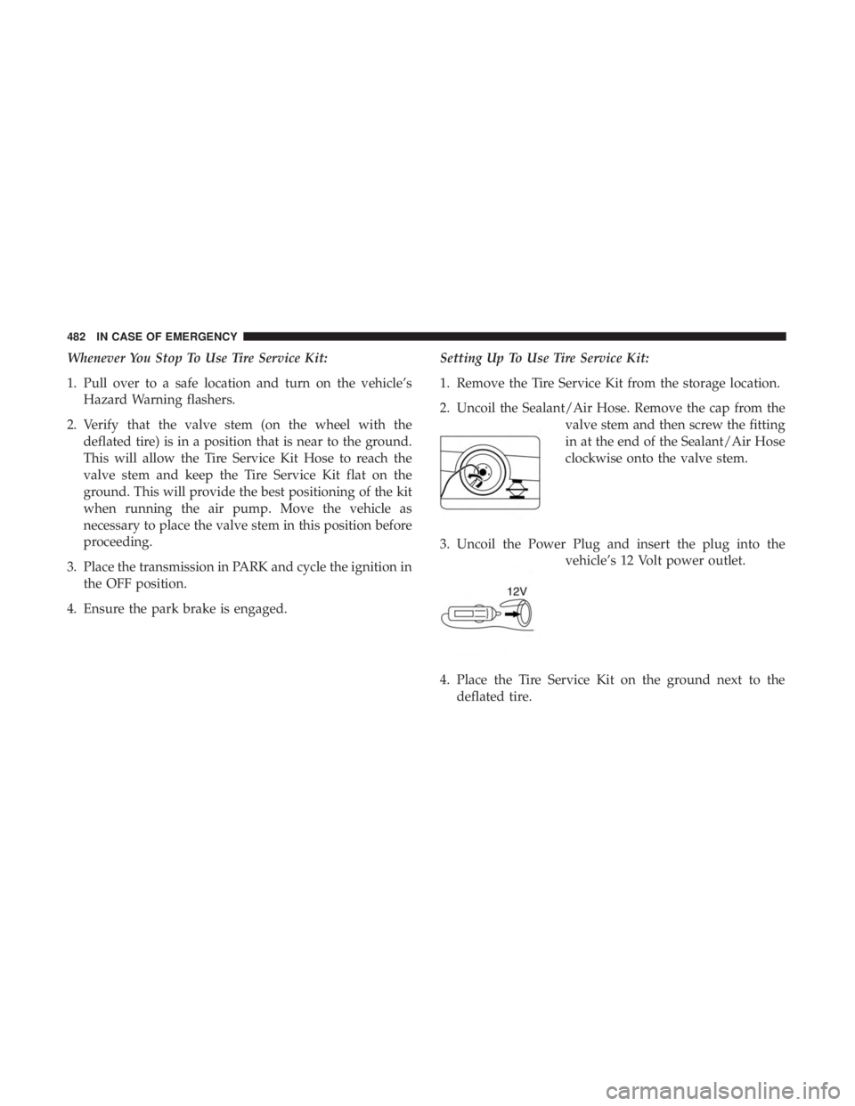
3. Uncoil the Power Plug and insert the plug into the vehicle’s 12 Volt power outlet.
4. Place the Tire Service Kit on the ground next to the deflated tire.
482 IN CASE OF EMERGENCY
Page 491 of 718
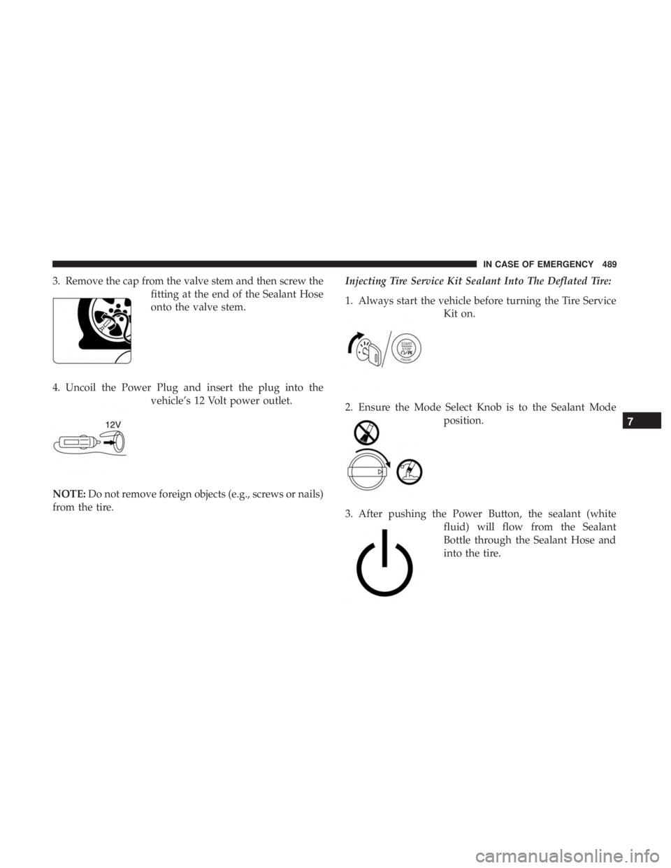
3. Remove the cap from the valve stem and then screw thefitting at the end of the Sealant Hose
onto the valve stem.
4. Uncoil the Power Plug and insert the plug into the vehicle’s 12 Volt power outlet.
NOTE: Do not remove foreign objects (e.g., screws or nails)
from the tire. Injecting Tire Service Kit Sealant Into The Deflated Tire:
1. Always start the vehicle before turning the Tire Service
Kit on.
2. Ensure the Mode Select Knob is to the Sealant Mode position.
3. After pushing the Power Button, the sealant (white fluid) will flow from the Sealant
Bottle through the Sealant Hose and
into the tire.
7
IN CASE OF EMERGENCY 489
Page 492 of 718
NOTE:Sealant may leak out through the puncture in the
tire.
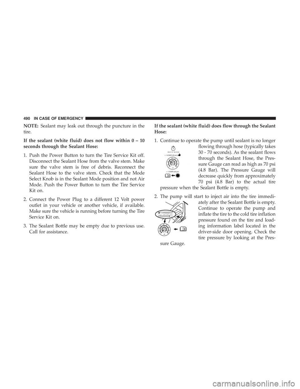
If the sealant (white fluid) does not flow within0–10
seconds through the Sealant Hose:
1. Push the Power Button to turn the Tire Service Kit off. Disconnect the Sealant Hose from the valve stem. Make
sure the valve stem is free of debris. Reconnect the
Sealant Hose to the valve stem. Check that the Mode
Select Knob is in the Sealant Mode position and not Air
Mode. Push the Power Button to turn the Tire Service
Kit on.
2. Connect the Power Plug to a different 12 Volt power outlet in your vehicle or another vehicle, if available.
Make sure the vehicle is running before turning the Tire
Service Kit on.
3. The Sealant Bottle may be empty due to previous use. Call for assistance. If the sealant (white fluid) does flow through the Sealant
Hose:
1. Continue to operate the pump until sealant is no longer
flowing through hose (typically takes
30 - 70 seconds). As the sealant flows
through the Sealant Hose, the Pres-
sure Gauge can read as high as 70 psi
(4.8 Bar). The Pressure Gauge will
decrease quickly from approximately
70 psi (4.8 Bar) to the actual tire
pressure when the Sealant Bottle is empty.
2. The pump will start to inject air into the tire immedi- ately after the Sealant Bottle is empty.
Continue to operate the pump and
inflate the tire to the cold tire inflation
pressure found on the tire and load-
ing information label located in the
driver-side door opening. Check the
tire pressure by looking at the Pres-
sure Gauge.
490 IN CASE OF EMERGENCY
Page 494 of 718
After Driving:
Pull over to a safe location. Refer to “Whenever You Stop
To Use Tire Service Kit” in this section before continuing.
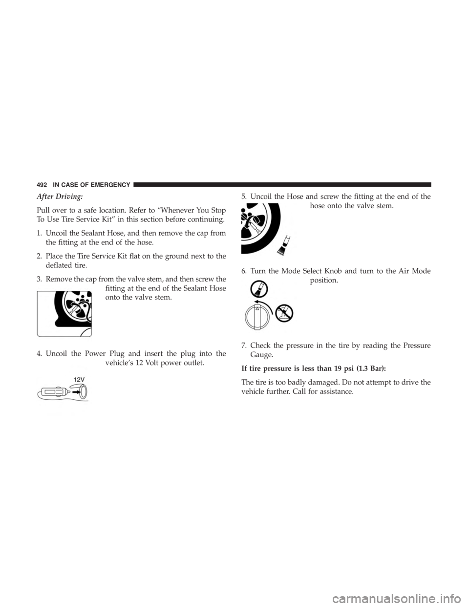
1. Uncoil the Sealant Hose, and then remove the cap fromthe fitting at the end of the hose.
2. Place the Tire Service Kit flat on the ground next to the deflated tire.
3. Remove the cap from the valve stem, and then screw the fitting at the end of the Sealant Hose
onto the valve stem.
4. Uncoil the Power Plug and insert the plug into the vehicle’s 12 Volt power outlet. 5. Uncoil the Hose and screw the fitting at the end of the
hose onto the valve stem.
6. Turn the Mode Select Knob and turn to the Air Mode position.
7. Check the pressure in the tire by reading the Pressure Gauge.
If tire pressure is less than 19 psi (1.3 Bar):
The tire is too badly damaged. Do not attempt to drive the
vehicle further. Call for assistance.
492 IN CASE OF EMERGENCY