Egr CHRYSLER PACIFICA 2019 Owners Manual
[x] Cancel search | Manufacturer: CHRYSLER, Model Year: 2019, Model line: PACIFICA, Model: CHRYSLER PACIFICA 2019Pages: 718, PDF Size: 8.6 MB
Page 26 of 718
To Lock The Doors And Liftgate
Push and release the lock button on the key fob to lock all
doors and liftgate. The hazard lights will flash once and the
horn will chirp once to acknowledge the signal. Settings in
radio can change to lights only, chirp only, or both.
Refer to “Keyless Enter-N-Go — Passive Entry” in “Getting
To Know Your Vehicle” for further information.
Key Fob With Remote Control And Integrated Vehicle
Key
If one or more doors are open or the liftgate is open, the
doors can be locked. This is signaled by a quick flash of the
turn signals.
Vehicles Equipped With Keyless Enter-N-Go — Passive
Entry
If one or more doors are open, or the liftgate is open, the
doors can be locked. The doors will unlock again only if the
key is inside the passenger compartment.
Key Fob Battery Replacement
The recommended replacement battery is one CR2032
battery.
NOTE:
•Batteries contain harmful chemicals. Dispose old batter-
ies by placing them in correct containers according to the
law or by taking them to a dealership, where they will be
handled appropriately.
• Perchlorate Material — special handling may apply. See
www.dtsc.ca.gov/hazardouswaste/perchlorate
• Do not touch the battery terminals that are on the back
housing or the printed circuit board.
1. Remove the emergency key by pushing the mechanical release button on the side of the key fob with your
thumb and then pull the key out with your other hand.
24 GETTING TO KNOW YOUR VEHICLE
Page 154 of 718
Gas props support the liftgate in the open position. How-
ever, because the gas pressure drops with temperature, it
may be necessary to assist the props when opening the
liftgate in cold weather.
NOTE:Allow the power system to open the liftgate.
Manually pushing or pulling the liftgate may activate the
liftgate obstacle detection feature and stop the power
operation or reverse its direction.
WARNING!
During power operation, personal injury or cargo
damage may occur. Ensure the liftgate travel path is
clear. Make sure the liftgate is closed and latched
before driving away.
Cargo Area Features
Cargo Area Storage
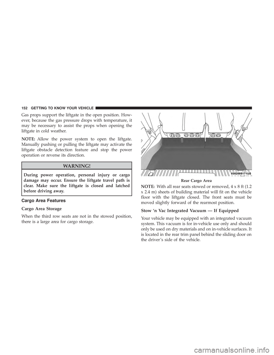
When the third row seats are not in the stowed position,
there is a large area for cargo storage. NOTE:
With all rear seats stowed or removed,4x8ft(1.2
x 2.4 m) sheets of building material will fit on the vehicle
floor with the liftgate closed. The front seats must be
moved slightly forward of the rearmost position.
Stow ‘n Vac Integrated Vacuum — If Equipped
Your vehicle may be equipped with an integrated vacuum
system. This vacuum is for in-vehicle use only and should
only be used on dry materials and on in-vehicle surfaces. It
is located in the rear trim panel behind the sliding door on
the driver ’s side of the vehicle.
Rear Cargo Area
152 GETTING TO KNOW YOUR VEHICLE
Page 178 of 718
WARNING!
To avoid serious injury or death:
•Only devices designed for use in this type of outlet
should be inserted into any 12 Volt outlet.
• Do not touch with wet hands.
(Continued)
WARNING! (Continued)
•Close the lid when not in use and while driving the
vehicle.
• If this outlet is mishandled, it may cause an electric
shock and failure.
CAUTION!
• Many accessories that can be plugged in draw power
from the vehicle’s battery, even when not in use (i.e.,
cellular phones, etc.). Eventually, if plugged in long
enough, the vehicle’s battery will discharge suffi-
ciently to degrade battery life and/or prevent the
engine from starting.
• Accessories that draw higher power (i.e., coolers,
vacuum cleaners, lights, etc.) will degrade the battery
even more quickly. Only use these intermittently and
with greater caution.
• After the use of high power draw accessories, or long
periods of the vehicle not being started (with acces-
sories still plugged in), the vehicle must be driven a
sufficient length of time to allow the generator to
recharge the vehicle’s battery.
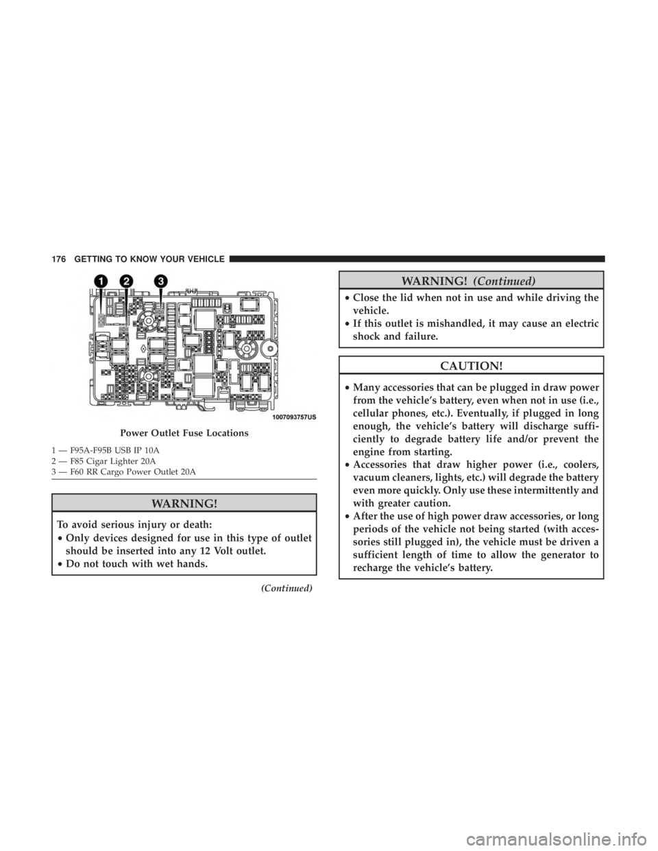
Power Outlet Fuse Locations
1 — F95A-F95B USB IP 10A
2 — F85 Cigar Lighter 20A
3 — F60 RR Cargo Power Outlet 20A 176 GETTING TO KNOW YOUR VEHICLE
Page 208 of 718
NOTE:The light may flash momentarily during sharp
cornering maneuvers, which change fluid level conditions.
The vehicle should have service performed, and the brake
fluid level checked.
If brake failure is indicated, immediate repair is necessary.
WARNING!
Driving a vehicle with the red brake light on is
dangerous. Part of the brake system may have failed. It
will take longer to stop the vehicle. You could have a
collision. Have the vehicle checked immediately.
Vehicles equipped with the Anti-Lock Brake System (ABS)
are also equipped with Electronic Brake Force Distribution
(EBD). In the event of an EBD failure, the Brake Warning
Light will turn on along with the ABS Light. Immediate
repair to the ABS system is required.
Operation of the Brake Warning Light can be checked by
turning the ignition switch from the OFF position to the
ON/RUN position. The light should illuminate for ap-
proximately two seconds. The light should then turn off
unless the parking brake is applied or a brake fault is
detected. If the light does not illuminate, have the light
inspected by an authorized dealer. The light also will turn on when the parking brake is
applied with the ignition switch in the ON/RUN position.
NOTE:
This light shows only that the parking brake is
applied. It does not show the degree of brake application.
— Door Open Warning Light — If Equipped
This warning light will illuminate when a door is ajar/
open and not fully closed. This indicator will reflect which
doors are open.
NOTE: If the vehicle is moving, there will also be a single
chime.
— Electric Power Steering Fault Warning Light
This warning light will turn on when there’s a fault with
the EPS (Electric Power Steering) system. Refer to “Power
Steering” in “Starting And Operating” for further informa-
tion.
WARNING!
Continued operation with reduced assist could pose a
safety risk to yourself and others. Service should be
obtained as soon as possible.
206 GETTING TO KNOW YOUR INSTRUMENT PANEL
Page 223 of 718
WARNING!(Continued)
•The capabilities of an ABS equipped vehicle must
never be exploited in a reckless or dangerous manner
that could jeopardize the user ’s safety or the safety of
others.
ABS is designed to function with the OEM tires. Modifica-
tion may result in degraded ABS performance.
Anti-Lock Brake Warning Light
The yellow “Anti-Lock Brake Warning Light” will turn on
when the ignition is turned to the ON/RUN mode and
may stay on for as long as four seconds.
If the “Anti-Lock Brake Warning Light” remains on or
comes on while driving, it indicates that the anti-lock
portion of the brake system is not functioning and that
service is required. However, the conventional brake sys-
tem will continue to operate normally if the “Anti-Lock
Brake Warning Light” is on.
If the “Anti-Lock Brake Warning Light” is on, the brake
system should be serviced as soon as possible to restore the benefits of anti-lock brakes. If the “Anti-Lock Brake Warn-
ing Light” does not come on when the ignition is turned to
the ON/RUN mode, have the light repaired as soon as
possible.
Electronic Brake Control System
Your vehicle is equipped with an advanced Electronic
Brake Control system (EBC). This system includes Elec-
tronic Brake Force Distribution (EBD), Anti-Lock Brake
System (ABS), Brake Assist System (BAS), Hill Start Assist
(HSA), Traction Control System (TCS), Electronic Stability
Control (ESC), and Electronic Roll Mitigation (ERM). These
systems work together to enhance both vehicle stability
and control in various driving conditions.
Your vehicle may also be equipped with Ready Alert
Braking (RAB), Rain Brake Support (RBS), Trailer Sway
Control (TSC), and Dynamic Steering Torque (DST).
Traction Control System (TCS)
This system monitors the amount of wheel spin of each of
the driven wheels. If wheel spin is detected, the TCS may
apply brake pressure to the spinning wheel(s) and/or
reduce vehicle power to provide enhanced acceleration
and stability. A feature of the TCS, Brake Limited Differen-
tial (BLD), functions similar to a limited slip differential
5
SAFETY 221
Page 227 of 718
WARNING!(Continued)
the performance of the ESC system. Changes to the
steering system, suspension, braking system, tire
type and size or wheel size may adversely affect ESC
performance. Improperly inflated and unevenly
worn tires may also degrade ESC performance. Any
vehicle modification or poor vehicle maintenance
that reduces the effectiveness of the ESC system can
increase the risk of loss of vehicle control, vehicle
rollover, personal injury and death.
ESC Operating Modes
NOTE:Depending upon model and mode of operation, the
ESC system may have multiple operating modes.
ESC On
This is the normal operating mode for the ESC. Whenever
the vehicle is started, the ESC system will be in this mode.
This mode should be used for most driving conditions.
Alternate ESC modes should only be used for specific
reasons as noted in the following paragraphs. Partial Off
The “Partial Off” mode is intended for times when a more
spirited driving experience is desired. This mode may
modify TCS and ESC thresholds for activation, which
allows for more wheel spin than normally allowed. This
mode may be useful if the vehicle becomes stuck.
To enter the “Partial Off” mode, momentarily push the
“ESC Off” button and the “ESC Off Indicator Light” will
illuminate. To turn the ESC on again, momentarily push
the “ESC Off” button and the “ESC Off Indicator Light”
will turn off.
NOTE:
When driving with snow chains, or when starting
off in deep snow, sand, or gravel, it may be desirable to
allow more wheel spin. This can be accomplished by
momentarily pushing the “ESC Off” button to enter partial
mode “Partial Off” mode. Once the situation requiring
“Partial Off” mode is overcome, turn ESC back on by
momentarily pushing the “ESC Off” button. This may be
done while the vehicle is in motion.
5
SAFETY 225
Page 233 of 718
If the system detects degraded performance due to con-
tamination or foreign objects, a message will warn you of a
blocked sensor and the warning indicators in side view
mirrors will be on. The warning indicators will remain
illuminated until blockage clearing conditions are met.
First clear the fascia area around the sensors of the block-
age. After removing the blockage, the following procedure
can be used to reset the system:
•Cycle the ignition from on to off and then back on.
If the blockage message is still present after cycling the
ignition and driving in traffic, check again for a blockage.
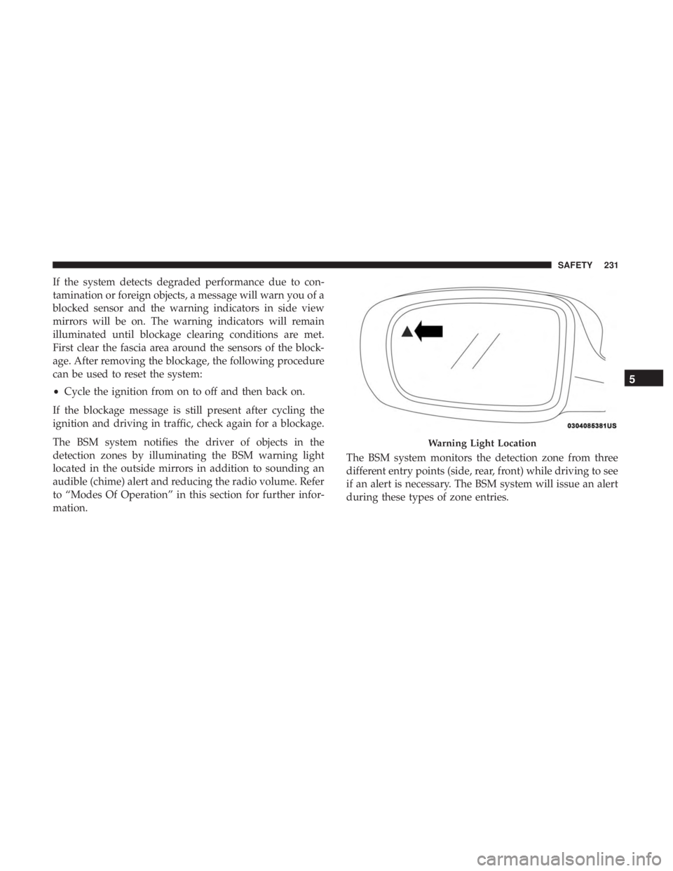
The BSM system notifies the driver of objects in the
detection zones by illuminating the BSM warning light
located in the outside mirrors in addition to sounding an
audible (chime) alert and reducing the radio volume. Refer
to “Modes Of Operation” in this section for further infor-
mation. The BSM system monitors the detection zone from three
different entry points (side, rear, front) while driving to see
if an alert is necessary. The BSM system will issue an alert
during these types of zone entries.
Warning Light Location
5
SAFETY 231
Page 255 of 718
Lap/Shoulder Belt Untwisting Procedure
Use the following procedure to untwist a twisted lap/
shoulder belt.
1. Position the latch plate as close as possible to the anchorpoint.
2. At about 6 to 12 inches (15 to 30 cm) above the latch plate, grasp and twist the seat belt webbing 180 degrees
to create a fold that begins immediately above the latch
plate.
3. Slide the latch plate upward over the folded webbing. The folded webbing must enter the slot at the top of the
latch plate.
4. Continue to slide the latch plate up until it clears the folded webbing and the seat belt is no longer twisted.
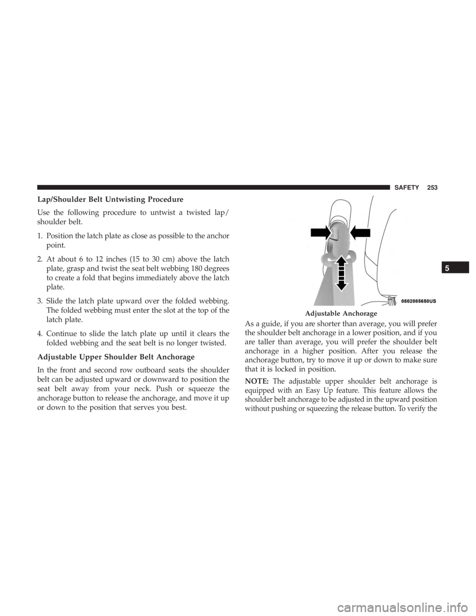
Adjustable Upper Shoulder Belt Anchorage
In the front and second row outboard seats the shoulder
belt can be adjusted upward or downward to position the
seat belt away from your neck. Push or squeeze the
anchorage button to release the anchorage, and move it up
or down to the position that serves you best. As a guide, if you are shorter than average, you will prefer
the shoulder belt anchorage in a lower position, and if you
are taller than average, you will prefer the shoulder belt
anchorage in a higher position. After you release the
anchorage button, try to move it up or down to make sure
that it is locked in position.
NOTE:
The adjustable upper shoulder belt anchorage is
equipped with an Easy Up feature. This feature allows the
shoulder belt anchorage to be adjusted in the upward position
without pushing or squeezing the release button. To verify the
Adjustable Anchorage
5
SAFETY 253
Page 331 of 718
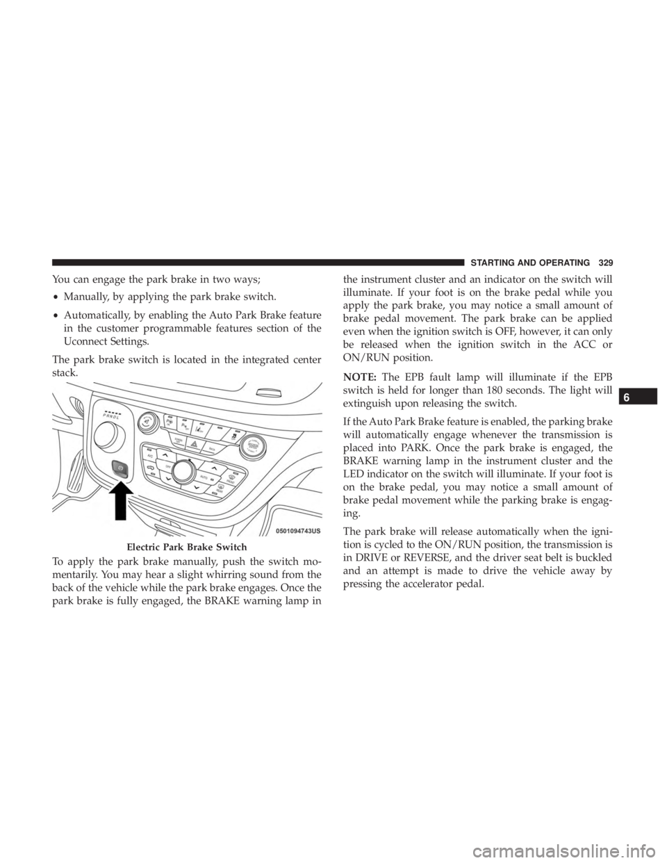
You can engage the park brake in two ways;
•Manually, by applying the park brake switch.
• Automatically, by enabling the Auto Park Brake feature
in the customer programmable features section of the
Uconnect Settings.
The park brake switch is located in the integrated center
stack.
To apply the park brake manually, push the switch mo-
mentarily. You may hear a slight whirring sound from the
back of the vehicle while the park brake engages. Once the
park brake is fully engaged, the BRAKE warning lamp in the instrument cluster and an indicator on the switch will
illuminate. If your foot is on the brake pedal while you
apply the park brake, you may notice a small amount of
brake pedal movement. The park brake can be applied
even when the ignition switch is OFF, however, it can only
be released when the ignition switch in the ACC or
ON/RUN position.
NOTE:
The EPB fault lamp will illuminate if the EPB
switch is held for longer than 180 seconds. The light will
extinguish upon releasing the switch.
If the Auto Park Brake feature is enabled, the parking brake
will automatically engage whenever the transmission is
placed into PARK. Once the park brake is engaged, the
BRAKE warning lamp in the instrument cluster and the
LED indicator on the switch will illuminate. If your foot is
on the brake pedal, you may notice a small amount of
brake pedal movement while the parking brake is engag-
ing.
The park brake will release automatically when the igni-
tion is cycled to the ON/RUN position, the transmission is
in DRIVE or REVERSE, and the driver seat belt is buckled
and an attempt is made to drive the vehicle away by
pressing the accelerator pedal.
Electric Park Brake Switch
6
STARTING AND OPERATING 329
Page 363 of 718
When the condition that deactivated the system is no
longer present, the system will return to the “Adaptive
Cruise Control Off” state and will resume function by
simply reactivating it.
NOTE:If the “ACC/FCW Unavailable Wipe Front Radar
Sensor” message occurs frequently (e.g. more than once on
every trip) without any snow, rain, mud, or other obstruc-
tion, have the radar sensor realigned at your authorized
dealer.
“Clean Front Windshield” Warning
The “ACC/FCW Limited Functionality Clean Front Wind-
shield” warning will display and also a chime will indicate
when conditions temporarily limit system performance.
This most often occurs at times of poor visibility, such as in
snow or heavy rain and fog. The ACC system may also
become temporarily blinded due to obstructions, such as
mud, dirt, or ice on windshield, driving directly into the
sun and fog on the inside of glass. In these cases, the
instrument cluster display will show “ACC/FCW Limited
Functionality Clean Front Windshield” and the system will
have degraded performance.
The “ACC/FCW Limited Functionality Clean Front Wind-
shield” message can sometimes be displayed while driving
in adverse weather conditions. The ACC/FCW system will recover after the vehicle has left these areas. Under rare
conditions, when the camera is not tracking any vehicles or
objects in its path this warning may temporarily occur.
If weather conditions are not a factor, the driver should
examine the windshield and the camera located on the
back side of the inside rear view mirror. They may require
cleaning or removal of an obstruction.
When the condition that created limited functionality is no
longer present, the system will return to full functionality.
NOTE:
If the “ACC/FCW Limited Functionality Clean
Front Windshield” message occurs frequently (e.g. more
than once on every trip) without any snow, rain, mud, or
other obstruction, have the windshield and forward facing
camera inspected at your authorized dealer.
Service ACC/FCW Warning
If the system turns off, and the instrument cluster displays
“ACC/FCW Unavailable Service Required” or “Cruise/
FCW Unavailable Service Required”, there may be an
internal system fault or a temporary malfunction that
limits ACC functionality. Although the vehicle is still
6
STARTING AND OPERATING 361