USB CHRYSLER PACIFICA 2020 Owners Manual
[x] Cancel search | Manufacturer: CHRYSLER, Model Year: 2020, Model line: PACIFICA, Model: CHRYSLER PACIFICA 2020Pages: 516, PDF Size: 28.69 MB
Page 9 of 516
7
TECHNICAL SPECIFICATIONS
IDENTIFICATION DATA ...................................... 388Vehicle Identification Number ..................388
BRAKE SYSTEM ................................................. 388
WHEEL AND TIRE TORQUE
SPECIFICATIONS ................................................ 388 Torque Specifications ................................388
FUEL REQUIREMENTS ...................................... 389 3.6L Engine ...............................................389Reformulated Gasoline .............................390Materials Added To Fuel ..........................390
Gasoline/Oxygenate Blends......................390
Do Not Use E-85 In Non-Flex Fuel
Vehicles ......................................................391 CNG And LP Fuel System Modifications ...391MMT In Gasoline ........................................391
Fuel System Cautions ................................391Carbon Monoxide Warnings .....................392
FLUID CAPACITIES ............................................. 393
FLUIDS AND LUBRICANTS ................................ 394 Engine.........................................................394
Chassis .......................................................396
MULTIMEDIA
UCONNECT SYSTEMS ....................................... 397
CYBERSECURITY ............................................... 397
UCONNECT SETTINGS ....................................... 398
Customer Programmable Features —
Uconnect 4 Settings .................................398 Customer Programmable Features —
Uconnect 4C/4C NAV Settings ................. 415 SAFETY AND GENERAL INFORMATION ........... 436
Safety Guidelines....................................... 436
UCONNECT 4 WITH 7-INCH DISPLAY ..............437
Introduction................................................ 437
Radio Mode ................................................ 438
Media Mode ............................................... 447Phone Mode ............................................... 454
STEERING WHEEL AUDIO CONTROLS — IF
EQUIPPED ..........................................................467
Radio Operation ......................................... 467
Media Mode ............................................... 467
AUX/USB/MP3 CONTROL ................................. 468
UCONNECT THEATER — IF EQUIPPED ............. 469
Uconnect Theater Overview ...................... 469
Getting Started .......................................... 469Accessing The System From The Uconnect
System ........................................................ 469 Uconnect Theater Controls ....................... 470
Accessing The System From The Uconnect
Theater Rear Screens................................ 470 Pairing The Remote ................................... 471
Unpairing The Remote............................... 472Media Sources ........................................... 472
Uconnect Theater Remote Control ........... 473
Uconnect Theater Home Screen And
Controls ...................................................... 474 General Information .................................. 475
Play A DVD/Blu-ray™ Or USB Media File
From Uconnect System ............................. 475 Disc Menu .................................................. 477
Blu-ray™ Controls – Disc Specific
Functions ................................................... 477 Uconnect Theater Apps ............................. 477
Using The Rear Video USB Port ................ 479
Play Video Games ...................................... 479
Headphones Operation ............................. 480
Display Settings ......................................... 481Listening To Audio With The Screen
Closed......................................................... 482 Rear Climate Controls ............................... 482Accessibility — If Equipped ........................ 484
Wireless Streaming — If Equipped............ 484
BD And DVD Region Codes ....................... 485Product Agreement.................................... 487General Information .................................. 489
FCC/IC Regulatory Notices........................ 490
RADIO OPERATION AND MOBILE PHONES.... 491
Regulatory And Safety Information .......... 491
UCONNECT VOICE RECOGNITION QUICK
TIPS .................................................................... 493
Introducing Uconnect ................................ 493
Get Started................................................. 493Basic Voice Commands ............................ 494Radio .......................................................... 494
20_RU_OM_EN_US_t.book Page 7
Page 120 of 516
118GETTING TO KNOW YOUR VEHICLE
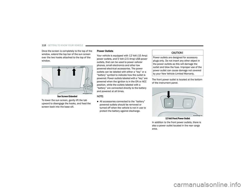
Once the screen is completely to the top of the
window, extend the top bar of the sun screen
over the two hooks attached to the top of the
window.
Sun Screen Extended
To lower the sun screen, gently lift the tab
upward to disengage the hooks, and feed the
screen back into the base sill.Power Outlets
Your vehicle is equipped with 12 Volt (15 Amp)
power outlets, and 5 Volt (2.5 Amp) USB power
outlets, that can be used to power cellular
phones, small electronics and other low
powered electrical accessories. The power
outlets can be labeled with either a “key” or a
“battery” symbol to indicate how the outlet is
powered. Power outlets labeled with a “key” are
powered when the ignition is in the ON or ACC
position, while the outlets labeled with a
“battery” are connected directly to the battery
and powered at all times.
NOTE:
All accessories connected to the “battery”
powered outlets should be removed or
turned off when the vehicle is not in use to
protect the battery against discharge. The front power outlet is located at the bottom
of the instrument panel.
12 Volt Front Power Outlet
In addition to the front power outlets, there is
also a power outlet located in the rear cargo
area.
CAUTION!
Power outlets are designed for accessory
plugs only. Do not insert any other object in
the power outlets as this will damage the
outlet and blow the fuse. Improper use of the
power outlet can cause damage not covered
by your New Vehicle Limited Warranty.
20_RU_OM_EN_US_t.book Page 118
Page 121 of 516
GETTING TO KNOW YOUR VEHICLE119
(Continued)
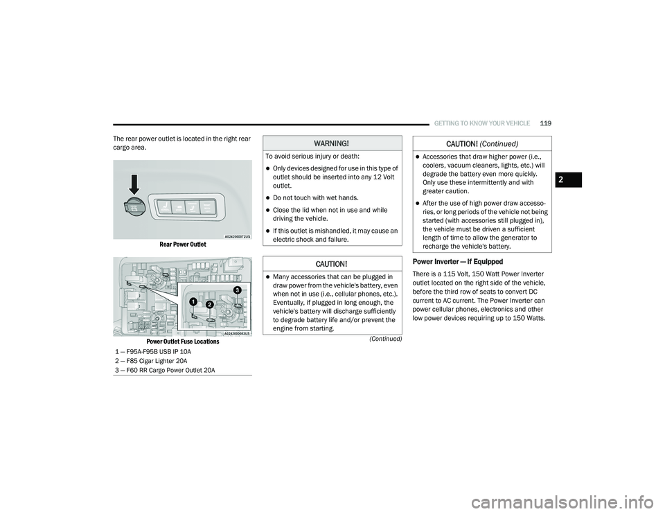
The rear power outlet is located in the right rear
cargo area.
Rear Power Outlet
Power Outlet Fuse Locations
Power Inverter — If Equipped
There is a 115 Volt, 150 Watt Power Inverter
outlet located on the right side of the vehicle,
before the third row of seats to convert DC
current to AC current. The Power Inverter can
power cellular phones, electronics and other
low power devices requiring up to 150 Watts.
1 — F95A-F95B USB IP 10A
2 — F85 Cigar Lighter 20A
3 — F60 RR Cargo Power Outlet 20A
WARNING!
To avoid serious injury or death:
Only devices designed for use in this type of
outlet should be inserted into any 12 Volt
outlet.
Do not touch with wet hands.
Close the lid when not in use and while
driving the vehicle.
If this outlet is mishandled, it may cause an
electric shock and failure.
CAUTION!
Many accessories that can be plugged in
draw power from the vehicle's battery, even
when not in use (i.e., cellular phones, etc.).
Eventually, if plugged in long enough, the
vehicle's battery will discharge sufficiently
to degrade battery life and/or prevent the
engine from starting.
Accessories that draw higher power (i.e.,
coolers, vacuum cleaners, lights, etc.) will
degrade the battery even more quickly.
Only use these intermittently and with
greater caution.
After the use of high power draw accesso -
ries, or long periods of the vehicle not being
started (with accessories still plugged in),
the vehicle must be driven a sufficient
length of time to allow the generator to
recharge the vehicle's battery.
CAUTION! (Continued)
2
20_RU_OM_EN_US_t.book Page 119
Page 141 of 516
GETTING TO KNOW YOUR INSTRUMENT PANEL139
Loss of the battery charge may indicate one or
more of the following conditions:
The charging system cannot deliver enough
electrical power to the vehicle system
because the electrical loads are larger than
the capability of charging system. The
charging system is still functioning properly.
Turning on all possible vehicle electrical
loads (e.g. HVAC to max settings, exterior and
interior lights, overloaded power outlets +12
Volts, 150W, USB ports) during certain
driving conditions (city driving, towing,
frequent stopping).
Installing options like additional lights,
upfitter electrical accessories, audio
systems, alarms and similar devices.
Unusual driving cycles (short trips separated
by long parking periods).
The vehicle was parked for an extended
period of time (weeks, months).
The battery was recently replaced and was
not charged completely.
The battery was discharged by an electrical
load left on when the vehicle was parked.
The battery was used for an extended period
with the engine not running to supply radio,
lights, chargers, +12 Volt portable appli-
ances like vacuum cleaners, game consoles
and similar devices.
What to do when an electrical load reduction
action message is present (“Battery Saver On”
or “Battery Saver Mode”)
During a trip:
Reduce power to unnecessary loads if
possible:
Turn off redundant lights (interior or exte -
rior)
Check what may be plugged in to power
outlets +12 Volts, 150W, USB ports
Check HVAC settings (blower, tempera -
ture)
Check the audio settings (volume) After a trip:
Check if any aftermarket equipment was
installed (additional lights, upfitter electrical
accessories, audio systems, alarms) and
review specifications if any (load and Ignition
Off Draw currents).
Evaluate the latest driving cycles (distance,
driving time and parking time).
The vehicle should have service performed if
the message is still present during consecu
-
tive trips and the evaluation of the vehicle
and driving pattern did not help to identify the
cause.
Instrument Cluster Display Programmable
Features Screen Setup
Push the up or down arrow button to scroll
through the Menu Items until the Screen Setup
displays in the instrument cluster display. Push
the OK button to enter Screen Setup. The
Screen Setup feature allows you to change what
information is displayed in the instrument
cluster display as well as the location that
information is displayed.
3
20_RU_OM_EN_US_t.book Page 139
Page 316 of 516
314IN CASE OF EMERGENCY
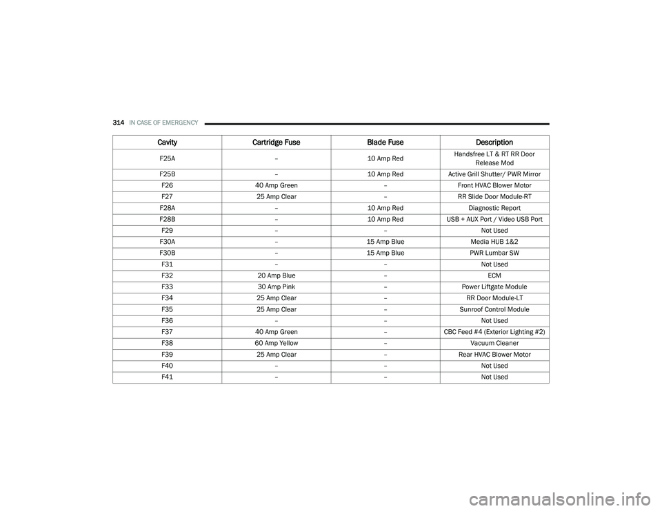
F25A –10 Amp RedHandsfree LT & RT RR Door
Release Mod
F25B –10 Amp RedActive Grill Shutter/ PWR Mirror
F26 40 Amp Green –Front HVAC Blower Motor
F27 25 Amp Clear –RR Slide Door Module-RT
F28A –10 Amp Red Diagnostic Report
F28B –10 Amp RedUSB + AUX Port / Video USB Port
F29 ––Not Used
F30A –15 Amp Blue Media HUB 1&2
F30B –15 Amp Blue PWR Lumbar SW
F31 ––Not Used
F32 20 Amp Blue –ECM
F33 30 Amp Pink –Power Liftgate Module
F34 25 Amp Clear –RR Door Module-LT
F35 25 Amp Clear –Sunroof Control Module
F36 ––Not Used
F37 40 Amp Green –CBC Feed #4 (Exterior Lighting #2)
F38 60 Amp Yellow –Vacuum Cleaner
F39 25 Amp Clear –Rear HVAC Blower Motor
F40 ––Not Used
F41 ––Not Used
CavityCartridge Fuse Blade FuseDescription
20_RU_OM_EN_US_t.book Page 314
Page 319 of 516
IN CASE OF EMERGENCY317
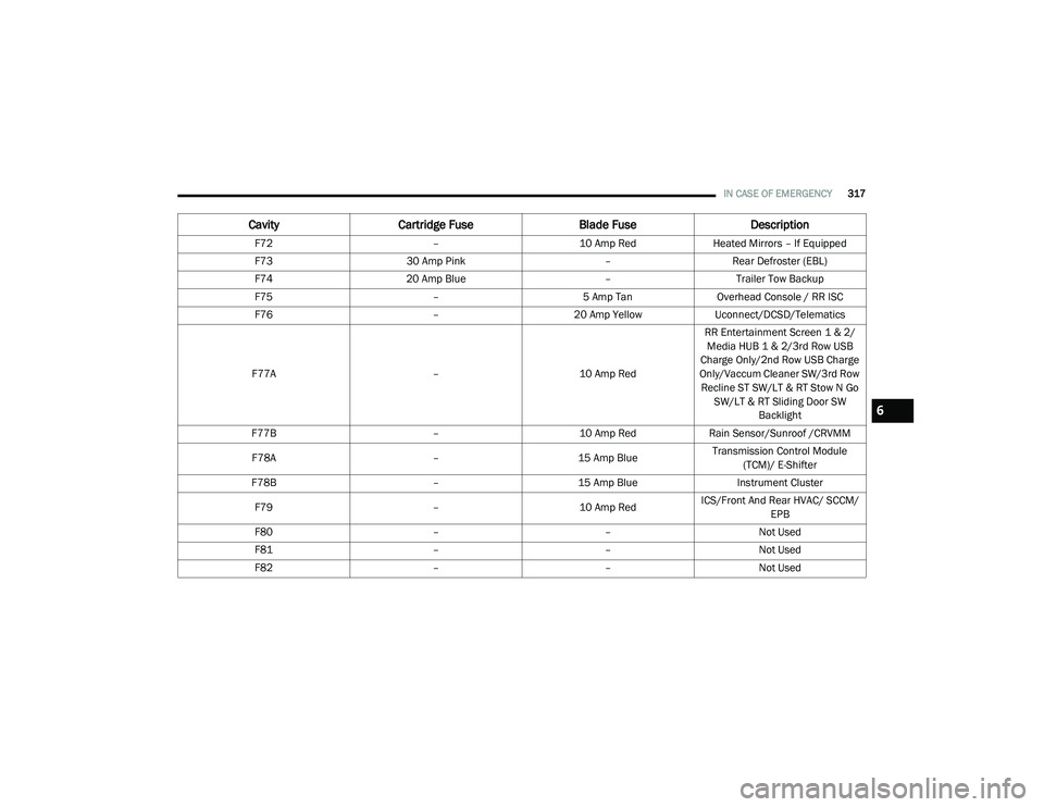
F72 –10 Amp RedHeated Mirrors – If Equipped
F73 30 Amp Pink –Rear Defroster (EBL)
F74 20 Amp Blue –Trailer Tow Backup
F75 –5 Amp TanOverhead Console / RR ISC
F76 –20 Amp YellowUconnect/DCSD/Telematics
F77A –10 Amp RedRR Entertainment Screen 1 & 2/
Media HUB 1 & 2/3rd Row USB
Charge Only/2nd Row USB Charge
Only/Vaccum Cleaner SW/3rd Row Recline ST SW/LT & RT Stow N Go SW/LT & RT Sliding Door SW Backlight
F77B –10 Amp RedRain Sensor/Sunroof /CRVMM
F78A –15 Amp BlueTransmission Control Module
(TCM)/ E-Shifter
F78B –15 Amp Blue Instrument Cluster
F79 –10 Amp RedICS/Front And Rear HVAC/ SCCM/
EPB
F80 ––Not Used
F81 ––Not Used
F82 ––Not Used
CavityCartridge Fuse Blade FuseDescription
6
20_RU_OM_EN_US_t.book Page 317
Page 320 of 516
318IN CASE OF EMERGENCY
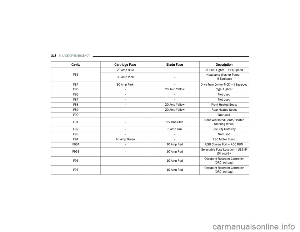
F83 20 Amp Blue
–TT Park Lights — If Equipped
30 Amp Pink – Headlamp Washer Pump —
If Equipped F84 30 Amp Pink
–
Drive Train Control MOD — If Equipped
F85
–20 Amp Yellow Cigar Lighter
F86 ––Not Used
F87 ––Not Used
F88 –20 Amp Yellow Front Heated Seats
F89 –20 Amp Yellow Rear Heated Seats
F90 ––Not Used
F91 –15 Amp BlueFront Ventilated Seats/Heated
Steering Wheel
F92 –5 Amp Tan Security Gateway
F93 ––Not Used
F94 40 Amp Green –ESC Motor Pump
F95A –10 Amp RedUSB Charge Port — ACC RUN
F95B –10 Amp RedSelectable Fuse Location – USB IP
(Direct) B+
F96 –10 Amp RedOccupant Restraint Controller
(ORC) (Airbag)
F97 –10 Amp RedOccupant Restraint Controller
(ORC) (Airbag)
Cavity Cartridge Fuse Blade FuseDescription
20_RU_OM_EN_US_t.book Page 318
Page 399 of 516
397
(Continued)
MULTIMEDIA
UCONNECT SYSTEMS
For detailed information about your Uconnect
4/4C/4C Nav With 8.4-inch Display system, refer
to your Uconnect Owner’s Manual Supplement.
NOTE:
Uconnect screen images are for illustration
purposes only and may not reflect exact soft-
ware for your vehicle.
CYBERSECURITY
Your vehicle may be a connected vehicle and
may be equipped with both wired and wireless
networks. These networks allow your vehicle to
send and receive information. This information
allows systems and features in your vehicle to
function properly.
Your vehicle may be equipped with certain
security features to reduce the risk of
unauthorized and unlawful access to vehicle
systems and wireless communications. Vehicle
software technology continues to evolve over
time and FCA US LLC, working with its suppliers,
evaluates and takes appropriate steps as
needed. Similar to a computer or other devices, your vehicle may require software updates to
improve the usability and performance of your
systems or to reduce the potential risk of
unauthorized and unlawful access to your
vehicle systems.
The risk of unauthorized and unlawful access to
your vehicle systems may still exist, even if the
most recent version of vehicle software (such as
Uconnect software) is installed.
NOTE:
FCA US LLC or your dealer may contact you
directly regarding software updates.
To help further improve vehicle security and
minimize the potential risk of a security
breach, vehicle owners should:
Routinely check www.driveuconnect.com
(US Residents) or www.driveuconnect.ca
(Canadian Residents) to learn about
available Uconnect software updates.
Only connect and use trusted media
devices (e.g. personal mobile phones,
USBs, CDs).
WARNING!
It is not possible to know or to predict all of
the possible outcomes if your vehicle’s
systems are breached. It may be possible
that vehicle systems, including safety related
systems, could be impaired or a loss of
vehicle control could occur that may result in
an accident involving serious injury or death.
ONLY insert media (e.g., USB, SD card, or CD)
into your vehicle if it came from a trusted
source. Media of unknown origin could
possibly contain malicious software, and if
installed in your vehicle, it may increase the
possibility for vehicle systems to be breached.
As always, if you experience unusual
vehicle behavior, take your vehicle to your
nearest authorized dealer immediately.
WARNING!
(Continued)
9
20_RU_OM_EN_US_t.book Page 397
Page 436 of 516
434MULTIMEDIA
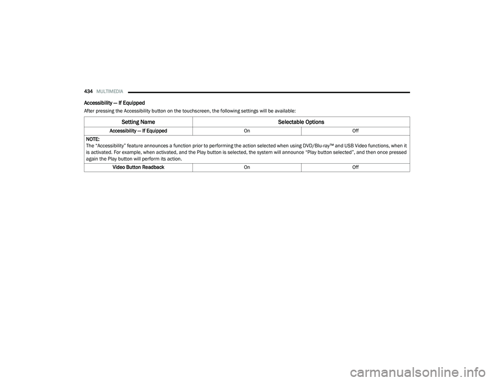
Accessibility — If Equipped
After pressing the Accessibility button on the touchscreen, the following settings will be available:
Setting Name Selectable Options
Accessibility — If EquippedOnOff
NOTE:
The “Accessibility” feature announces a function prior to performing the action selected when using DVD/Blu-ray™ and USB Video functions, when it
is activated. For example, when activated, and the Play button is selected, the system will announce “Play button selected”, and then once pressed
again the Play button will perform its action. Video Button Readback OnOff
20_RU_OM_EN_US_t.book Page 434
Page 439 of 516
MULTIMEDIA437
Care And Maintenance
Touchscreen
Do not press the touchscreen with any hard or
sharp objects (pen, USB stick, jewelry, etc.),
which could scratch the touchscreen surface!
Do not spray any liquid or caustic chemicals
directly on the screen! Use a clean and dry
microfiber lens cleaning cloth in order to
clean the touchscreen.
If necessary, use a lint-free cloth dampened
with a cleaning solution, such as isopropyl
alcohol or an isopropyl alcohol and water solu -
tion ratio of 50:50. Be sure to follow the solvent
manufacturer's precautions and directions.
UCONNECT 4 WITH 7-INCH DISPLAY
Introduction
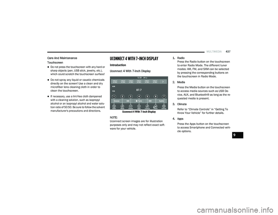
Uconnect 4 With 7-Inch Display
Uconnect 4 With 7-inch Display
NOTE:
Uconnect screen images are for illustration
purposes only and may not reflect exact soft -
ware for your vehicle.
1. Radio
Press the Radio button on the touchscreen
to enter Radio Mode. The different tuner
modes: AM, FM, and SXM can be selected
by pressing the corresponding buttons on
the touchscreen in Radio Mode.
2. Media Press the Media button on the touchscreen
to access media sources such as USB De -
vice, AUX, and Bluetooth® as long as the re -
quested media is present.
3. Climate Refer to “Climate Controls” in “Getting To
Know Your Vehicle” for further details.
4. Apps Press the Apps button on the touchscreen
to access Smartphone and Connected vehi -
cle options.
9
20_RU_OM_EN_US_t.book Page 437