interior lights CHRYSLER PACIFICA 2020 Owners Manual
[x] Cancel search | Manufacturer: CHRYSLER, Model Year: 2020, Model line: PACIFICA, Model: CHRYSLER PACIFICA 2020Pages: 516, PDF Size: 28.69 MB
Page 5 of 516

3
MIRRORS ..............................................................59 Inside Day/Night Mirror — If Equipped ....... 59
Automatic Dimming Mirror —
If Equipped .................................................. 60 Outside Mirrors ........................................... 60
Driver's Outside Automatic Dimming
Mirror — If Equipped .................................... 60 Conversation Mirror ..................................... 60
Power Mirrors — If Equipped ...................... 61
Outside Mirrors Folding Feature ................. 61
Heated Mirrors — If Equipped ..................... 61
Tilt Side Mirrors In Reverse (Available With
Memory Seat Only) — If Equipped............... 61 Power Folding Mirrors — If Equipped .......... 62
Illuminated Vanity Mirrors — If Equipped .. 62
EXTERIOR LIGHTS ................................................63
Multifunction Lever ...................................... 63
Headlight Switch .......................................... 63
Daytime Running Lights (DRLs) —
If Equipped ................................................... 63 High/Low Beam Switch ............................... 64
Automatic High Beam — If Equipped ......... 64
Flash-To-Pass .............................................. 64
Automatic Headlights — If Equipped .......... 64
Headlights On With Wipers — If Equipped.. 65
Headlight Delay — If Equipped .................... 65
Lights-On Reminder .................................... 65
Front Fog Lights — If Equipped .................. 65
Turn Signals ................................................. 65
Lane Change Assist — If Equipped ............. 66
Battery Protection ....................................... 66 INTERIOR LIGHTS ................................................ 66
Courtesy/Interior Lighting .......................... 66
WINDSHIELD WIPER AND WASHERS .............. 68
Windshield Wiper Operation ....................... 68
Rain Sensing Wipers — If Equipped............ 69
Rear Wiper And Washer .............................. 70
CLIMATE CONTROLS ........................................... 70
Manual Climate Controls Overview ............ 70
Automatic Climate Control Overview .......... 80
Climate Control Functions........................... 90
Automatic Temperature Control (ATC) — If
Equipped ..................................................... 90 Operating Tips ............................................. 91
WINDOWS ............................................................. 93
Power Windows............................................ 93
PANORAMIC SUNROOF — IF EQUIPPED ........... 95
Opening Sunroof .......................................... 95
Closing Sunroof............................................ 96
Wind Buffeting ............................................. 96
Power Sunshade — If Equipped .................. 96
Pinch Protect Feature.................................. 97
Sunroof Maintenance.................................. 97
Ignition Off Operation .................................. 97
HOOD .................................................................... 97
Opening ........................................................ 97
Closing .......................................................... 98 LIFTGATE ................................................................99
Opening ........................................................ 99
Closing.......................................................... 99
Power Liftgate — If Equipped .................... 100 Hands-Free Liftgate — If Equipped ........... 101
Cargo Area Features ................................. 103
GARAGE DOOR OPENER — IF EQUIPPED ....... 109
Before You Begin Programming
HomeLink® ................................................ 109 Canadian/Gate Operator Programming... 111
Using HomeLink®...................................... 112
Security ...................................................... 112Troubleshooting Tips ................................. 112General Information .................................. 113
INTERNAL EQUIPMENT ..................................... 113
Storage ....................................................... 113
Sun Screens — If Equipped ....................... 117Power Outlets ............................................ 118Power Inverter — If Equipped ................... 119
Cigar Lighter — If Equipped ...................... 120
Smoker's Package Kit — If Equipped ....... 120
Overhead Sunglass Storage ..................... 120
STOW ‘N PLACE ROOF RACK —
IF EQUIPPED ...................................................... 121
Deploying The Crossbars .......................... 121
Stowing The Crossbars.............................. 123
20_RU_OM_EN_US_t.book Page 3
Page 65 of 516

GETTING TO KNOW YOUR VEHICLE63
EXTERIOR LIGHTS
Multifunction Lever
The multifunction lever is located on the left
side of the steering column. The multifunction
lever controls the turn signals, headlight high/
low beams, and flash-to-pass functions.
Multifunction Lever
Headlight Switch
The headlight switch is located on the left side
of the instrument panel. The switch controls the
operation of the headlights, parking lights,
instrument panel lights, interior lights and the
fog lights.
Headlight Switch
From the O (off) position, rotate the headlight
switch clockwise to the first detent for parking
light and instrument panel light operation.
Rotate the headlight switch to the second
detent for headlight, parking light and
instrument panel operation.
Daytime Running Lights (DRLs) — If
Equipped
The headlights or LED light bars on your vehicle
will illuminate when the engine is started. This
provides a constant lights on condition until the
ignition is placed in the OFF position. If the
parking brake is applied, the Daytime Running
Lights (DRLs) will turn off. Also, if a turn signal is
activated, the DRL lamp on the same side of the
vehicle will turn off for the duration of the turn
signal activation. Once the turn signal is no
longer active, the DRL lamp will illuminate.
1 — Rotate Headlight Control
2 — Ambient Light Dimmer Control
3 — Instrument Panel Dimmer Control
4 — Push Fog Light Control
2
20_RU_OM_EN_US_t.book Page 63
Page 68 of 516

66GETTING TO KNOW YOUR VEHICLE
NOTE:
If either light remains on and does not flash, or
there is a very fast flash rate, check for a defec -
tive outside light bulb. If an indicator fails to
light when the lever is moved, it would suggest
that the indicator bulb is defective.
Turn Signal Warning
If the vehicle electronics sense that the vehicle
has traveled for about 1 mile (1.6 km) with the
turn signals on, a chime will sound and a
message will display in the cluster to alert the
driver.
Lane Change Assist — If Equipped
Tap the multifunction lever up or down once,
without moving beyond the detent, and the turn
signal (right or left) will flash three times then
automatically turn off.
Battery Protection
This feature provides battery protection to avoid
wearing down the battery if the headlights or
parking lights are left on for extended periods of
time when the ignition is in the OFF position.
After eight minutes of the ignition being in the OFF position and the headlight switch in any
position other than OFF or AUTO, the lights will
turn off automatically until the next cycle of the
ignition or headlight switch.
The battery protection feature will be disabled if
the ignition is placed in any position other than
OFF during the eight minute delay.
INTERIOR LIGHTS
Courtesy/Interior Lighting
The courtesy light switches are used to turn the
courtesy lights on/off.
Courtesy Light Switches
To operate the courtesy lights, push either the
driver or passenger light switch.
NOTE:
Before exiting the vehicle, make sure that the
interior lights are turned off. This will prevent
the battery from discharging once the doors
are closed.
If a light is left on, it will automatically be
turned off approximately 10 minutes after
the ignition is in the STOP/OFF position.
Rear Courtesy/Reading Lights — If Equipped
Located above the rear passengers are
courtesy/reading lights. The lights turn on when
a front door, a sliding door or the liftgate is
opened. If your vehicle is equipped with Remote
Keyless Entry (RKE) the lights will also turn on
when the unlock button on the key fob is
pushed.
20_RU_OM_EN_US_t.book Page 66
Page 69 of 516

GETTING TO KNOW YOUR VEHICLE67
The courtesy lights also function as reading
lights. Push the lens to turn these lights on while
inside the vehicle. Push the lens a second time
to turn each light off.
Ambient Light Control — If Equipped
Rotate the ambient dimmer control upward or
downward to increase or decrease the
brightness of the ambient light located in the
door handle lights, under instrument panel
lights, door map pocket lights, and cubby bin
lights.
Ambient Light/Door Handle Light Dimmer
Interior Lighting Off
Rotate the dimmer control on the right to the off
position (extreme bottom). The interior lights
will remain off when the doors or liftgate are
open.
Instrument Panel Dimmer Control
The instrument panel dimmer control is part of
the headlight switch, and is located on the
driver’s side of the instrument panel.
With the parking lights or headlights on, rotate
the instrument panel dimmer control upward or
downward to increase or decrease the
brightness of the instrument panel. At the top
detent of the instrument panel dimmer, all the
interior lights will also illuminate. At the bottom
most setting (extreme bottom) interior lights are
turned off (dome off), and the cluster, radio and
instrument lighting go to their lowest dimmable
setting.
Instrument Panel Dimmer
2
20_RU_OM_EN_US_t.book Page 67
Page 103 of 516
,
located in the upper left trim in the liftgate
op")
GETTING TO KNOW YOUR VEHICLE101
To Close The Liftgate
The liftgate can also be closed using the Rear
Interior Power Liftgate button (if equipped),
located in the upper left trim in the liftgate
opening.
Rear Interior Power Liftgate Switch
Lock The Vehicle
With a valid Passive Entry key fob within 5 ft
(1.5 m) of the liftgate, pushing the Passive Entry
lock button located to the right of the outside
handle will lock the vehicle.Hands-Free Liftgate — If Equipped
Hands-Free Liftgate Activation Zone
To open the liftgate using hands-free activation,
use a straight in and out kicking motion under
the vehicle activation zone in the general
location below the liftgate door handle. Do not
move your foot sideways or in a sweeping
motion or the sensors may not detect the
motion. Vehicles Equipped With A Trailer Tow Package
NOTE:
If your vehicle is equipped with the Trailer Tow
Package, the hands-free activation zone(s) for
the Power Liftgate will be located on the left and
right side of the receiver. Use a straight kicking
motion under either activation zone to open the
Hands-Free Liftgate.
Hands-Free Liftgate Trailer Tow Activation Zones
When a valid kicking motion is completed, the
liftgate will chime, the hazard lights will flash
and the liftgate will open after approximately
one second. This assumes all options are
enabled in the radio.
2
20_RU_OM_EN_US_t.book Page 101
Page 141 of 516

GETTING TO KNOW YOUR INSTRUMENT PANEL139
Loss of the battery charge may indicate one or
more of the following conditions:
The charging system cannot deliver enough
electrical power to the vehicle system
because the electrical loads are larger than
the capability of charging system. The
charging system is still functioning properly.
Turning on all possible vehicle electrical
loads (e.g. HVAC to max settings, exterior and
interior lights, overloaded power outlets +12
Volts, 150W, USB ports) during certain
driving conditions (city driving, towing,
frequent stopping).
Installing options like additional lights,
upfitter electrical accessories, audio
systems, alarms and similar devices.
Unusual driving cycles (short trips separated
by long parking periods).
The vehicle was parked for an extended
period of time (weeks, months).
The battery was recently replaced and was
not charged completely.
The battery was discharged by an electrical
load left on when the vehicle was parked.
The battery was used for an extended period
with the engine not running to supply radio,
lights, chargers, +12 Volt portable appli-
ances like vacuum cleaners, game consoles
and similar devices.
What to do when an electrical load reduction
action message is present (“Battery Saver On”
or “Battery Saver Mode”)
During a trip:
Reduce power to unnecessary loads if
possible:
Turn off redundant lights (interior or exte -
rior)
Check what may be plugged in to power
outlets +12 Volts, 150W, USB ports
Check HVAC settings (blower, tempera -
ture)
Check the audio settings (volume) After a trip:
Check if any aftermarket equipment was
installed (additional lights, upfitter electrical
accessories, audio systems, alarms) and
review specifications if any (load and Ignition
Off Draw currents).
Evaluate the latest driving cycles (distance,
driving time and parking time).
The vehicle should have service performed if
the message is still present during consecu
-
tive trips and the evaluation of the vehicle
and driving pattern did not help to identify the
cause.
Instrument Cluster Display Programmable
Features Screen Setup
Push the up or down arrow button to scroll
through the Menu Items until the Screen Setup
displays in the instrument cluster display. Push
the OK button to enter Screen Setup. The
Screen Setup feature allows you to change what
information is displayed in the instrument
cluster display as well as the location that
information is displayed.
3
20_RU_OM_EN_US_t.book Page 139
Page 198 of 516

196SAFETY
Enhanced Accident Response System
In the event of an impact, if the communication
network remains intact, and the power remains
intact, depending on the nature of the event,
the ORC will determine whether to have the
Enhanced Accident Response System perform
the following functions:
Cut off fuel to the engine (if equipped).
Cut off battery power to the electric motor (if
equipped).
Flash hazard lights as long as the battery has
power.
Turn on the interior lights, which remain on
as long as the battery has power or for
15 minutes from the intervention of the
Enhanced Accident Response System.
Unlock the power door locks. Your vehicle may also be designed to perform
any of these other functions in response to the
Enhanced Accident Response System:
Turn off the Fuel Filter Heater, Turn off the
HVAC Blower Motor, Close the HVAC Circula
-
tion Door
Cut off battery power to the:
Engine
Electric Motor (if equipped)
Electric power steering
Brake booster
Electric park brake
Automatic transmission gear selector
Horn
Front wiper
Headlamp washer pump NOTE:
After an accident, remember to cycle the ignition
to the STOP (OFF/LOCK) position and remove the
key from the ignition switch to avoid draining the
battery. Carefully check the vehicle for fuel leaks
in the engine compartment and on the ground
near the engine compartment and fuel tank
before resetting the system and starting the
engine. If there are no fuel leaks or damage to
the vehicle electrical devices (e.g. headlights)
after an accident, reset the system by following
the procedure described below. If you have any
doubt, contact an authorized dealer.
Enhanced Accident Response System Reset
Procedure
If applicable, refer to the “Hybrid Supplement”
for additional information.
In order to reset the Enhanced Accident
Response System functions after an event, the
ignition switch must be changed from ignition
START or ON/RUN to ignition OFF. Carefully
check the vehicle for fuel leaks in the engine
compartment and on the ground near the
engine compartment and fuel tank before
resetting the system and starting the engine.
20_RU_OM_EN_US_t.book Page 196
Page 317 of 516

F45 30 Amp Pink –Power Inverter
F46 30 Amp Pink")
IN CASE OF EMERGENCY315
F42 40 Amp Green –Folding Seat Module
F43 –20 Amp Yellow Fuel Pump Motor
F44 30 Amp Pink –CBC Feed #1 (Interior Lights)
F45 30 Amp Pink –Power Inverter
F46 30 Amp Pink –Driver Door Module
F47 30 Amp Pink –Passenger Door Module
F48 ––Not Used
F49 25 Amp Clear –RR Sliding Door Module-LT
F50 25 Amp Clear –RR Door Module-RT
F51 30 Amp Pink –Front Wiper
F52 30 Amp Pink –Brake Vacuum Pump
F53 ––Not Used
F54 40 Amp Green –ESP-ECU And Valves
F55A –15 Amp BlueRadio Frequency HUB/ Keyless
Ignition System (KIN) / (Electronic Steering Lock-BUX ONLY)
F55B –15 Amp BlueDVD / Video Routing Module (VRM
F56A –10 Amp RedFront and Rear HVAC Control
Module / Occupant Classification
Module (OCM)/Electronic Steering Lock (ESL)
F56B –10 Amp Red ESP/ESC
CavityCartridge Fuse Blade FuseDescription
6
20_RU_OM_EN_US_t.book Page 315
Page 347 of 516

345
SERVICING AND MAINTENANCE
SCHEDULED SERVICING
Your vehicle is equipped with an automatic oil
change indicator system. The oil change
indicator system will remind you that it is time to
take your vehicle in for scheduled maintenance.
Based on engine operation conditions, the oil
change indicator message will illuminate. This
means that service is required for your vehicle.
Operating conditions such as frequent short-trips,
trailer tow, extremely hot or cold ambient
temperatures will influence when the “Oil Change
Required” message is displayed. Severe
Operating Conditions can cause the change oil
message to illuminate as early as 3,500 miles
(5,600 km) since last reset. Have your vehicle
serviced as soon as possible, within the next
500 miles (805 km).
An authorized dealer will reset the oil change
indicator message after completing the
scheduled oil change. If a scheduled oil change
is performed by someone other than an
authorized dealer, the message can be reset by
referring to “Instrument Cluster Display” in
“Getting To Know Your Instrument Panel”.NOTE:
Under no circumstances should oil change
intervals exceed 10,000 miles (16,000 km),
12 months or 350 hours of engine run time,
whichever comes first. The 350 hours of engine
run or idle time is generally only a concern for
fleet customers.
Severe Duty All Models
Change Engine Oil at 4,000 miles (6,500 km) or
350 hours of engine run time if the vehicle is
operated in a dusty and off road environment or
is operated predominately at idle or only very
low engine RPM. This type of vehicle use is
considered Severe Duty.
Once A Month Or Before A Long Trip:Check engine oil level
Check windshield washer fluid level
Check tire pressure and look for unusual
wear or damage. Rotate tires at the first sign
of irregular wear, even if it occurs before the
oil indicator system turns on
Check the fluid levels of the coolant reservoir
and brake master cylinder, fill as needed
Check function of all interior and exterior
lights
Maintenance Plan
Required Maintenance Intervals
Refer to the required maintenance intervals.
7
20_RU_OM_EN_US_t.book Page 345
Page 403 of 516
MULTIMEDIA401
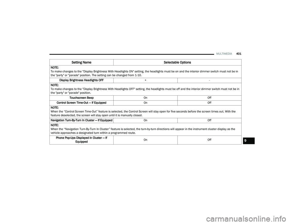
NOTE:
To make changes to the "Display Brightness With Headlights ON" setting, the headlights must be on and the interior dimmer switch must not be in
the "party" or "parade" position. The setting can be changed from 1-10.
Display Brightness Headlights OFF +-
NOTE:
To make changes to the "Display Brightness With Headlights OFF" setting, the headlights must be off and the interior dimmer switch must not be in
the "party" or "parade" position. Touchscreen Beep OnOff
Control Screen Time-Out — If Equipped OnOff
NOTE:
When the “Control Screen Time-Out” feature is selected, the Control Screen will stay open for five seconds before the screen times out. With the
feature deselected, the screen will stay open until it is manually closed.
Navigation Turn-By-Turn In Cluster — If Equipped OnOff
NOTE:
When the “Navigation Turn-By-Turn In Cluster” feature is selected, the turn-by-turn directions will appear in the instrument cluster display as the
vehicle approaches a designated turn within a programmed route. Phone Pop-Ups Displayed in Cluster — If Equipped On
Off
Setting Name Selectable Options
9
20_RU_OM_EN_US_t.book Page 401