rear lamp CHRYSLER PACIFICA 2020 Owners Manual
[x] Cancel search | Manufacturer: CHRYSLER, Model Year: 2020, Model line: PACIFICA, Model: CHRYSLER PACIFICA 2020Pages: 516, PDF Size: 28.69 MB
Page 151 of 516
GETTING TO KNOW YOUR INSTRUMENT PANEL149
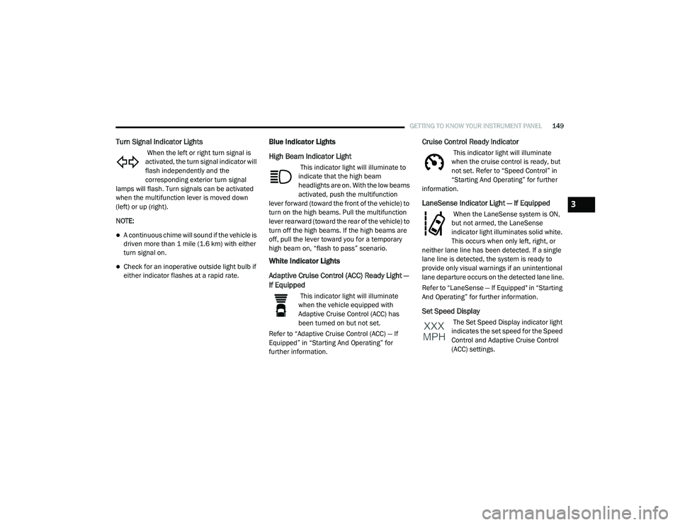
Turn Signal Indicator Lights
When the left or right turn signal is
activated, the turn signal indicator will
flash independently and the
corresponding exterior turn signal
lamps will flash. Turn signals can be activated
when the multifunction lever is moved down
(left) or up (right).
NOTE:
A continuous chime will sound if the vehicle is
driven more than 1 mile (1.6 km) with either
turn signal on.
Check for an inoperative outside light bulb if
either indicator flashes at a rapid rate.
Blue Indicator Lights
High Beam Indicator Light
This indicator light will illuminate to
indicate that the high beam
headlights are on. With the low beams
activated, push the multifunction
lever forward (toward the front of the vehicle) to
turn on the high beams. Pull the multifunction
lever rearward (toward the rear of the vehicle) to
turn off the high beams. If the high beams are
off, pull the lever toward you for a temporary
high beam on, “flash to pass” scenario.
White Indicator Lights
Adaptive Cruise Control (ACC) Ready Light —
If Equipped
This indicator light will illuminate
when the vehicle equipped with
Adaptive Cruise Control (ACC) has
been turned on but not set.
Refer to “Adaptive Cruise Control (ACC) — If
Equipped” in “Starting And Operating” for
further information.
Cruise Control Ready Indicator
This indicator light will illuminate
when the cruise control is ready, but
not set. Refer to “Speed Control” in
“Starting And Operating” for further
information.
LaneSense Indicator Light — If Equipped
When the LaneSense system is ON,
but not armed, the LaneSense
indicator light illuminates solid white.
This occurs when only left, right, or
neither lane line has been detected. If a single
lane line is detected, the system is ready to
provide only visual warnings if an unintentional
lane departure occurs on the detected lane line.
Refer to “LaneSense — If Equipped" in “Starting
And Operating” for further information.
Set Speed Display
The Set Speed Display indicator light
indicates the set speed for the Speed
Control and Adaptive Cruise Control
(ACC) settings.
3
20_RU_OM_EN_US_t.book Page 149
Page 162 of 516
160SAFETY
The Blind Spot Monitoring (BSM) system may
experience drop outs (blinking on and off) of
the side mirror Warning Indicator lamps
when a motorcycle or any small object
remains at the side of the vehicle for
extended periods of time (more than a couple
of seconds).
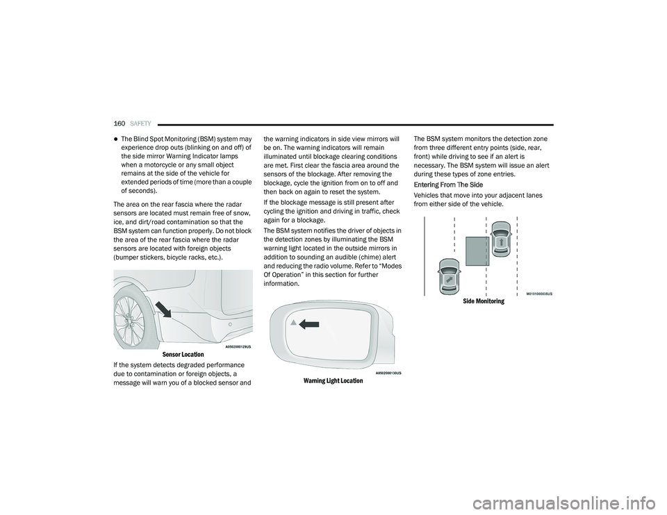
The area on the rear fascia where the radar
sensors are located must remain free of snow,
ice, and dirt/road contamination so that the
BSM system can function properly. Do not block
the area of the rear fascia where the radar
sensors are located with foreign objects
(bumper stickers, bicycle racks, etc.).
Sensor Location
If the system detects degraded performance
due to contamination or foreign objects, a
message will warn you of a blocked sensor and the warning indicators in side view mirrors will
be on. The warning indicators will remain
illuminated until blockage clearing conditions
are met. First clear the fascia area around the
sensors of the blockage. After removing the
blockage, cycle the ignition from on to off and
then back on again to reset the system.
If the blockage message is still present after
cycling the ignition and driving in traffic, check
again for a blockage.
The BSM system notifies the driver of objects in
the detection zones by illuminating the BSM
warning light located in the outside mirrors in
addition to sounding an audible (chime) alert
and reducing the radio volume. Refer to “Modes
Of Operation” in this section for further
information.
Warning Light Location
The BSM system monitors the detection zone
from three different entry points (side, rear,
front) while driving to see if an alert is
necessary. The BSM system will issue an alert
during these types of zone entries.
Entering From The Side
Vehicles that move into your adjacent lanes
from either side of the vehicle.
Side Monitoring
20_RU_OM_EN_US_t.book Page 160
Page 229 of 516
STARTING AND OPERATING227
If exceptional circumstances should make it
necessary to engage the park brake while the
vehicle is in motion, push on the electric park
brake switch for as long as engagement is
desired. The BRAKE warning lamp will
illuminate, and a continuous chime will sound.
The rear stop lamps will also be illuminated
automatically while the vehicle remains in
motion. To disengage the park brake while the vehicle is
in motion, release the switch. If the vehicle is
brought to a complete stop using the park
brake, when the vehicle reaches approximately
3 mph (4.8 km/h), the park brake will remain
engaged.
In the unlikely event of a malfunction of the
Electric Park Brake system, a yellow EPB fault
lamp will illuminate. This may be accompanied
by the BRAKE warning lamp flashing. In this
case, urgent service of the electric park brake
system is required. Do not rely on the park
brake to hold the vehicle stationary.
Auto Park Brake
The Electric Park Brake can be programmed to
be applied automatically whenever the vehicle
is at a standstill and the automatic transmission
is placed in PARK. Auto Park Brake is enabled
and disabled by customer selection through the
“Customer Programmable Features” section of
the “Uconnect Settings”.
SafeHold
SafeHold is a safety feature of the Electric Park
Brake System that will engage the park brake
automatically if the vehicle is left unsecured. If
the automatic transmission is not in PARK, the
seat belt is unbuckled, the driver door is open,
the vehicle is at a standstill, and there is no
attempt to depress the brake pedal or
accelerator pedal, the park brake will
automatically engage to prevent the vehicle
from rolling.
SafeHold can be temporarily bypassed by
pushing the Electric Park Brake Switch while the
driver door is open and brake pedal is pressed.
Once manually bypassed, SafeHold will be
enabled again once the vehicle reaches
12 mph (20 km/h) or the ignition is cycled to
the OFF position and back to ON again.
Brake Service Mode
We recommend having your brakes serviced by
an authorized dealer. You should only make
repairs for which you have the knowledge and
the right equipment. You should only enter
Brake Service Mode during brake service.
When servicing your rear brakes, it may be
necessary for you or your technician to push the
rear piston into the rear caliper bore. With the
Driving the vehicle with the parking brake
engaged, or repeated use of the parking
brake to slow the vehicle may cause
serious damage to the brake system.
CAUTION!
If the Brake System Warning Light remains on
with the parking brake released, a brake
system malfunction is indicated. Have the
brake system serviced by an authorized
dealer immediately.
WARNING!
(Continued)
5
20_RU_OM_EN_US_t.book Page 227
Page 230 of 516
228STARTING AND OPERATING
(Continued)
(Continued)
Electric Park Brake system, this can only be
done after retracting the Electric Park Brake
actuator. Fortunately, actuator retraction can
be done easily by entering the “Brake Service”
through the “Uconnect Settings” in your vehicle.
This menu based system will guide you through
the steps necessary to retract the EPB actuator
in order to perform rear brake service.
Brake Service Mode has requirements that
must be met in order to be activated:
The vehicle must be at a standstill.
The park brake must be unapplied.
The transmission must be in PARK or
NEUTRAL.
While in service mode, the Electric Park Brake
fault lamp will flash continuously while the
ignition switch is ON.
When brake service work is complete, the
following steps must be followed to reset the
parking brake system to normal operation:
Ensure the vehicle is at a standstill.
Press the brake pedal with moderate force.
Apply the Electric Park Brake Switch.
AUTOMATIC TRANSMISSION
WARNING!
You can be badly injured working on or
around a motor vehicle. Do only that service
work for which you have the knowledge and
the right equipment. If you have any doubt
about your ability to perform a service job,
take your vehicle to a competent mechanic.
WARNING!
Never use the PARK position as a substi -
tute for the parking brake. Always apply the
parking brake fully when exiting the vehicle
to guard against vehicle movement and
possible injury or damage.
Your vehicle could move and injure you and
others if it is not in PARK. Check by trying to
move the transmission gear selector out of
PARK with the brake pedal released. Make
sure the transmission is in PARK before
exiting the vehicle.
The transmission may not engage PARK if
the vehicle is moving. Always bring the
vehicle to a complete stop before shifting to
PARK, and verify that the transmission gear
position indicator solidly indicates PARK (P)
without blinking. Ensure that the vehicle is
completely stopped, and the PARK position
is properly indicated, before exiting the
vehicle.
It is dangerous to shift out of PARK or
NEUTRAL if the engine speed is higher than
idle speed. If your foot is not firmly pressing
the brake pedal, the vehicle could accel -
erate quickly forward or in reverse. You
could lose control of the vehicle and hit
someone or something. Only shift into gear
when the engine is idling normally and your
foot is firmly pressing the brake pedal.
WARNING! (Continued)
20_RU_OM_EN_US_t.book Page 228
Page 308 of 516
306IN CASE OF EMERGENCY
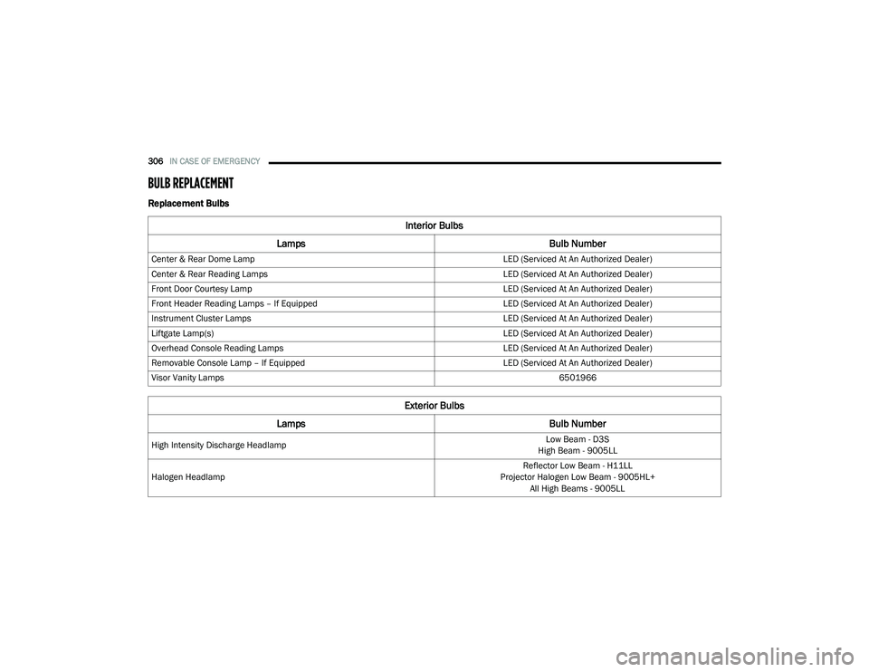
BULB REPLACEMENT
Replacement Bulbs
Interior Bulbs
Lamps Bulb Number
Center & Rear Dome Lamp LED (Serviced At An Authorized Dealer)
Center & Rear Reading Lamps LED (Serviced At An Authorized Dealer)
Front Door Courtesy Lamp LED (Serviced At An Authorized Dealer)
Front Header Reading Lamps – If Equipped LED (Serviced At An Authorized Dealer)
Instrument Cluster Lamps LED (Serviced At An Authorized Dealer)
Liftgate Lamp(s) LED (Serviced At An Authorized Dealer)
Overhead Console Reading Lamps LED (Serviced At An Authorized Dealer)
Removable Console Lamp – If Equipped LED (Serviced At An Authorized Dealer)
Visor Vanity Lamps 6501966
Exterior Bulbs
Lamps Bulb Number
High Intensity Discharge Headlamp Low Beam - D3S
High Beam - 9005LL
Halogen Headlamp Reflector Low Beam - H11LL
Projector Halogen Low Beam - 9005HL+ All High Beams - 9005LL
20_RU_OM_EN_US_t.book Page 306
Page 309 of 516
IN CASE OF EMERGENCY307
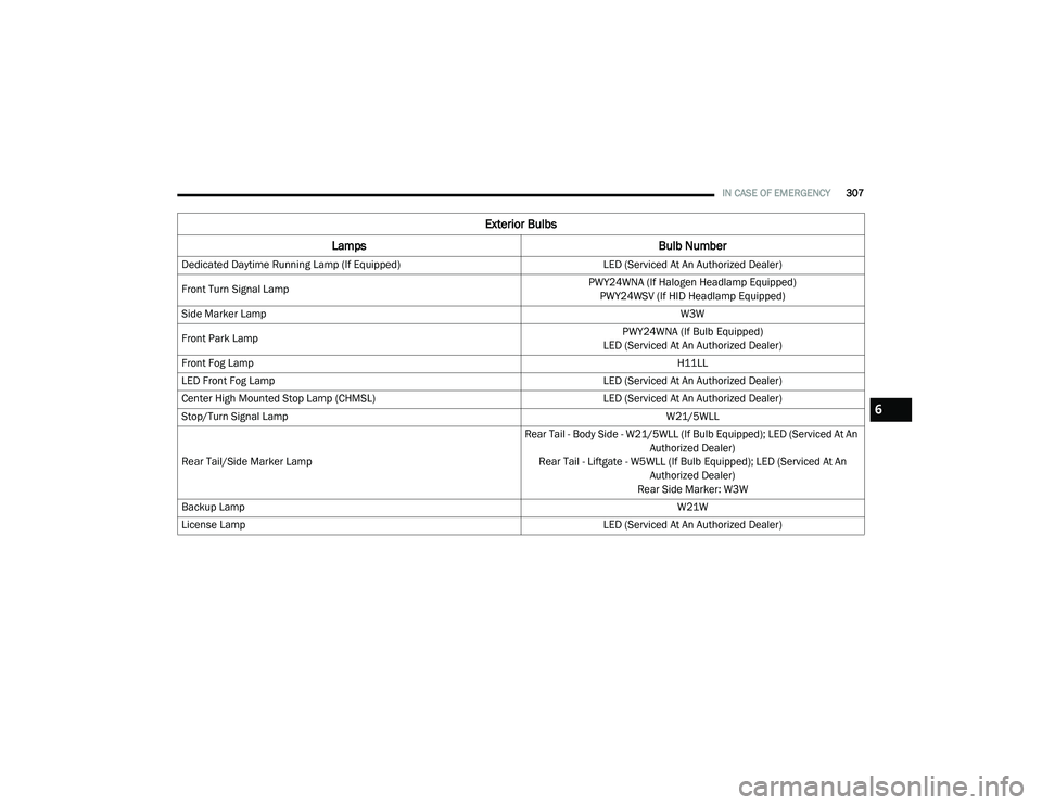
Dedicated Daytime Running Lamp (If Equipped) LED (Serviced At An Authorized Dealer)
Front Turn Signal Lamp PWY24WNA (If Halogen Headlamp Equipped)
PWY24WSV (If HID Headlamp Equipped)
Side Marker Lamp W3W
Front Park Lamp PWY24WNA (If Bulb Equipped)
LED (Serviced At An Authorized Dealer)
Front Fog Lamp H11LL
LED Front Fog Lamp LED (Serviced At An Authorized Dealer)
Center High Mounted Stop Lamp (CHMSL) LED (Serviced At An Authorized Dealer)
Stop/Turn Signal Lamp W21/5WLL
Rear Tail/Side Marker Lamp Rear Tail - Body Side - W21/5WLL (If Bulb Equipped); LED (Serviced At An
Authorized Dealer)
Rear Tail - Liftgate - W5WLL (If Bulb Equipped); LED (Serviced At An Authorized Dealer)
Rear Side Marker: W3W
Backup Lamp W21W
License Lamp LED (Serviced At An Authorized Dealer)
Exterior Bulbs
Lamps Bulb Number
6
20_RU_OM_EN_US_t.book Page 307
Page 311 of 516
IN CASE OF EMERGENCY309
5. Install the bulb and connector assembly
into the headlamp housing and rotate
clockwise to lock it in place.
6. Install the headlamp bulb cap in the headlamp housing and rotate clockwise to
lock it in place.
Front Turn Signal Lamp
1. Open the hood.
2. Twist the front turn signal lamp socket assembly counterclockwise, and then
remove the front turn signal lamp assembly
from the lamp housing.
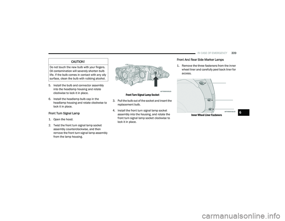
Front Turn Signal Lamp Socket
3. Pull the bulb out of the socket and insert the replacement bulb.
4. Install the front turn signal lamp socket assembly into the housing, and rotate the
front turn signal lamp socket clockwise to
lock it in place.
Front And Rear Side Marker Lamps
1. Remove the three fasteners from the inner wheel liner and carefully peel back liner for
access.
Inner Wheel Liner Fasteners
CAUTION!
Do not touch the new bulb with your fingers.
Oil contamination will severely shorten bulb
life. If the bulb comes in contact with any oily
surface, clean the bulb with rubbing alcohol.
6
20_RU_OM_EN_US_t.book Page 309
Page 312 of 516
310IN CASE OF EMERGENCY
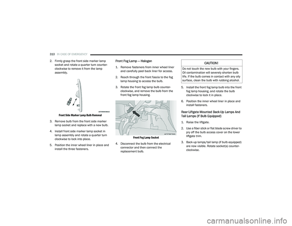
2. Firmly grasp the front side marker lamp
socket and rotate a quarter turn counter-
clockwise to remove it from the lamp
assembly.
Front Side Marker Lamp Bulb Removal
3. Remove bulb from the front side marker lamp socket and replace with a new bulb.
4. Install front side marker lamp socket in lamp assembly and rotate a quarter turn
clockwise to lock into place.
5. Position the inner wheel liner in place and install the three fasteners.Front Fog Lamp — Halogen
1. Remove fasteners from inner wheel liner and carefully peel back liner for access.
2. Reach through the front fascia to the fog lamp housing to access the bulb.
3. Rotate the front fog lamp bulb counter -
clockwise, and remove the bulb from the
front fog lamp housing.
Front Fog Lamp Socket
4. Disconnect the bulb from the electrical connector and then connect the
replacement bulb. 5. Install the front fog lamp bulb into the front
fog lamp housing, and rotate the bulb
clockwise to lock it in place.
6. Position the inner wheel liner in place and install fasteners.
Rear Liftgate Mounted Back-Up Lamps And
Tail Lamps (If Bulb Equipped)
1. Raise the liftgate.
2. Use a fiber stick or flat blade screw driver to pry off the bulb access cover on the lower
liftgate trim.
3. Back-up lamps/tail lamp (if bulb equipped) are now visible. Rotate socket(s) counter -
clockwise.
CAUTION!
Do not touch the new bulb with your fingers.
Oil contamination will severely shorten bulb
life. If the bulb comes in contact with any oily
surface, clean the bulb with rubbing alcohol.
20_RU_OM_EN_US_t.book Page 310
Page 313 of 516
IN CASE OF EMERGENCY311
(Continued)
4. Remove/replace bulb(s).
5. Reinstall the socket(s).
6. Reverse process to reinstall the liftgate trim.
Rear Bodyside Mounted Taillamps
1. Raise the liftgate.
2. Remove two torx head screws on the bodyside lamp using a T30 screwdriver.
3. Remove lamp from vehicle body and locate bulb socket on rear of lamp. Rotate socket
counterclockwise.
4. Remove/replace bulb(s).
5. Reinstall the socket(s).
6. Reverse process to reinstall the lamp onto vehicle.
Center High Mounted Stop Lamp (CHMSL)
The center high-mounted stop lamp is an LED
assembly. See an authorized dealer for
replacement.
Rear License Lamp
The rear license lamps are LED. See an
authorized dealer for replacement.
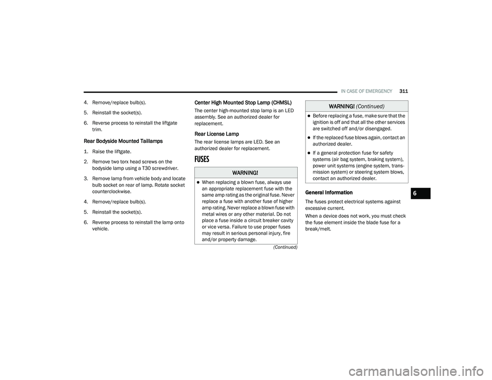
FUSES
General Information
The fuses protect electrical systems against
excessive current.
When a device does not work, you must check
the fuse element inside the blade fuse for a
break/melt.
WARNING!
When replacing a blown fuse, always use
an appropriate replacement fuse with the
same amp rating as the original fuse. Never
replace a fuse with another fuse of higher
amp rating. Never replace a blown fuse with
metal wires or any other material. Do not
place a fuse inside a circuit breaker cavity
or vice versa. Failure to use proper fuses
may result in serious personal injury, fire
and/or property damage.
Before replacing a fuse, make sure that the
ignition is off and that all the other services
are switched off and/or disengaged.
If the replaced fuse blows again, contact an
authorized dealer.
If a general protection fuse for safety
systems (air bag system, braking system),
power unit systems (engine system, trans -
mission system) or steering system blows,
contact an authorized dealer.
WARNING! (Continued)
6
20_RU_OM_EN_US_t.book Page 311
Page 318 of 516
316IN CASE OF EMERGENCY
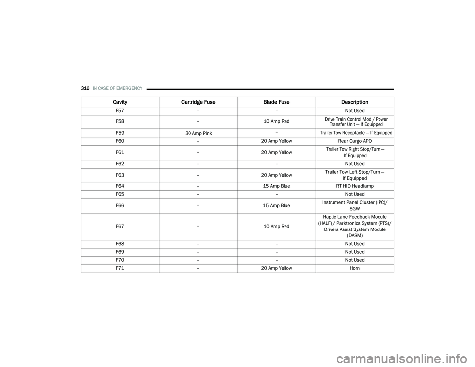
F57 ––Not Used
F58 – 10 Amp Red
Drive Train Control Mod / Power
Transfer Unit — If Equipped
F59
30 Amp Pink –
Trailer Tow Receptacle — If Equipped
F60
–20 Amp Yellow Rear Cargo APO
F61 –20 Amp Yellow
Trailer Tow Right Stop/Turn —
If Equipped
F62––Not Used
F63 –20 Amp Yellow Trailer Tow Left Stop/Turn —
If Equipped
F64–15 Amp Blue RT HID Headlamp
F65 ––Not Used
F66 –15 Amp BlueInstrument Panel Cluster (IPC)/
SGW
F67 –10 Amp RedHaptic Lane Feedback Module
(HALF) / Parktronics System (PTS)/ Drivers Assist System Module (DASM)
F68 ––Not Used
F69 ––Not Used
F70 ––Not Used
F71 –20 Amp Yellow Horn
CavityCartridge Fuse Blade FuseDescription
20_RU_OM_EN_US_t.book Page 316