start stop button CHRYSLER PACIFICA 2020 Owners Manual
[x] Cancel search | Manufacturer: CHRYSLER, Model Year: 2020, Model line: PACIFICA, Model: CHRYSLER PACIFICA 2020Pages: 516, PDF Size: 28.69 MB
Page 6 of 516
4
GETTING TO KNOW YOUR INSTRUMENT PANEL
INSTRUMENT CLUSTER..................................... 125
Instrument Cluster Descriptions ...............126
INSTRUMENT CLUSTER DISPLAY ................... 127
Instrument Cluster Display Location And
Controls ......................................................128 Oil Life Reset ..............................................129
Fuel And Oil Refresh Mode .......................129
KeySense Cluster Messages —
If Equipped .................................................130 Instrument Cluster Display Menu Items ..131
Battery Saver On/Battery Saver Mode
Message — Electrical Load Reduction
Actions — If Equipped ................................138 Instrument Cluster Display Programmable
Features Screen Setup.............................. 139
TRIP COMPUTER ............................................... 140
WARNING LIGHTS AND MESSAGES ............... 141
Red Warning Lights....................................141
Yellow Warning Lights ...............................144
Yellow Indicator Lights...............................147
Green Indicator Lights ...............................148
Blue Indicator Lights ..................................149White Indicator Lights................................149
ONBOARD DIAGNOSTIC SYSTEM — OBD II .... 150
Onboard Diagnostic System (OBD II)
Cybersecurity..............................................150
EMISSIONS INSPECTION AND MAINTENANCE
PROGRAMS ........................................................ 151
SAFETY
SAFETY FEATURES .............................................152 Anti-Lock Brake System (ABS) ................. 152
Electronic Brake Control (EBC) System ... 153
AUXILIARY DRIVING SYSTEMS.........................159 Blind Spot Monitoring (BSM) —
If Equipped ................................................. 159 Forward Collision Warning (FCW) With
Mitigation — If Equipped............................ 164 Tire Pressure Monitoring
System (TPMS) .......................................... 167
OCCUPANT RESTRAINT SYSTEMS .................. 171 Occupant Restraint Systems Features .... 171
Important Safety Precautions ................... 172
Seat Belt Systems ..................................... 172
Supplemental Restraint Systems (SRS)... 184
Child Restraints ......................................... 198
Transporting Pets ...................................... 215
SAFETY TIPS ....................................................... 216 Transporting Passengers .......................... 216Exhaust Gas .............................................. 216
Safety Checks You Should Make Inside
The Vehicle ................................................ 217 Periodic Safety Checks You Should Make
Outside The Vehicle ................................... 218
STARTING AND OPERATING
STARTING THE ENGINE .....................................219 Normal Starting.......................................... 219Cold Weather Operation (Below –22°F
Or −30°C) ................................................. 223 After Starting — Warming Up The
Engine ........................................................ 223 If Engine Fails To Start ............................. 223
To Turn Off The Engine Using ENGINE
START/STOP Button .................................. 223
ENGINE BLOCK HEATER — IF EQUIPPED ....... 224
ENGINE BREAK-IN RECOMMENDATIONS ...... 224
PARK BRAKE...................................................... 225 Electric Park Brake (EPB) ......................... 225
AUTOMATIC TRANSMISSION ........................... 228 Ignition Park Interlock ............................... 229Brake/Transmission Shift Interlock
System........................................................ 229 Nine-Speed Automatic Transmission ...... 230
Gear Ranges .............................................. 230
ACTIVE NOISE CANCELLATION ........................ 234
POWER STEERING............................................. 234
STOP/START SYSTEM — IF EQUIPPED ........... 235
Auto Stop/Start.......................................... 235
Possible Reasons The Engine Does Not
Autostop ..................................................... 235 To Start The Engine While In Auto
Stop/Start .................................................. 236 To Manually Turn Off The Stop/Start
System........................................................ 236 To Manually Turn On The Stop/Start
System........................................................ 237 System Malfunction................................... 237
20_RU_OM_EN_US_t.book Page 4
Page 15 of 516
GETTING TO KNOW YOUR VEHICLE13
Features/Benefits
Pre-installed on your Uconnect touchscreen radio
Enhanced search and browsing capability
Robust NAV application (if equipped)
Add selected topics to a fast-access Favor -
ites category
Icon and symbol glossary
Warranty information
Crucial driver information and assistance:
Operating Instructions
Warranty Information
Fluid Level Standards
Maintenance Schedules
Emergency Procedures
911 Contact and More
TIP:
When viewing a topic, tap the star icon to add it
to your Favorites, for easy access in the future.
KEYS
Key Fob
Your vehicle uses a keyless ignition system. The
ignition system consists of a key fob with
Remote Keyless Entry (RKE) and a START/STOP
push button ignition system. The RKE system
uses a receiver module in the vehicle that
wirelessly links with the key fob.
NOTE:
The key fob may not be found if it is located next
to a mobile phone, laptop or other electronic
device; these devices may block the key fob’s
wireless signal.
This system allows you to lock or unlock the
doors and liftgate, activate the Panic Alarm,
optional power liftgate, left power sliding door,
and right power sliding door from distances up
to approximately 66 ft (20 m) using a key fob.
When any button on the key fob is pushed, or when any signal is being transferred between
the key fob and the vehicle, an LED light on the
key fob will flash as an indicator. The key fob
does not need to be pointed at the vehicle to
activate the system.
NOTE:
The emergency key allows for entry into the
vehicle should the battery in the vehicle or the
key fob become depleted. The emergency key is
also for locking/unlocking the glove compart
-
ment. You can keep the emergency key with you
when valet parking.
2
20_RU_OM_EN_US_t.book Page 13
Page 16 of 516
14GETTING TO KNOW YOUR VEHICLE
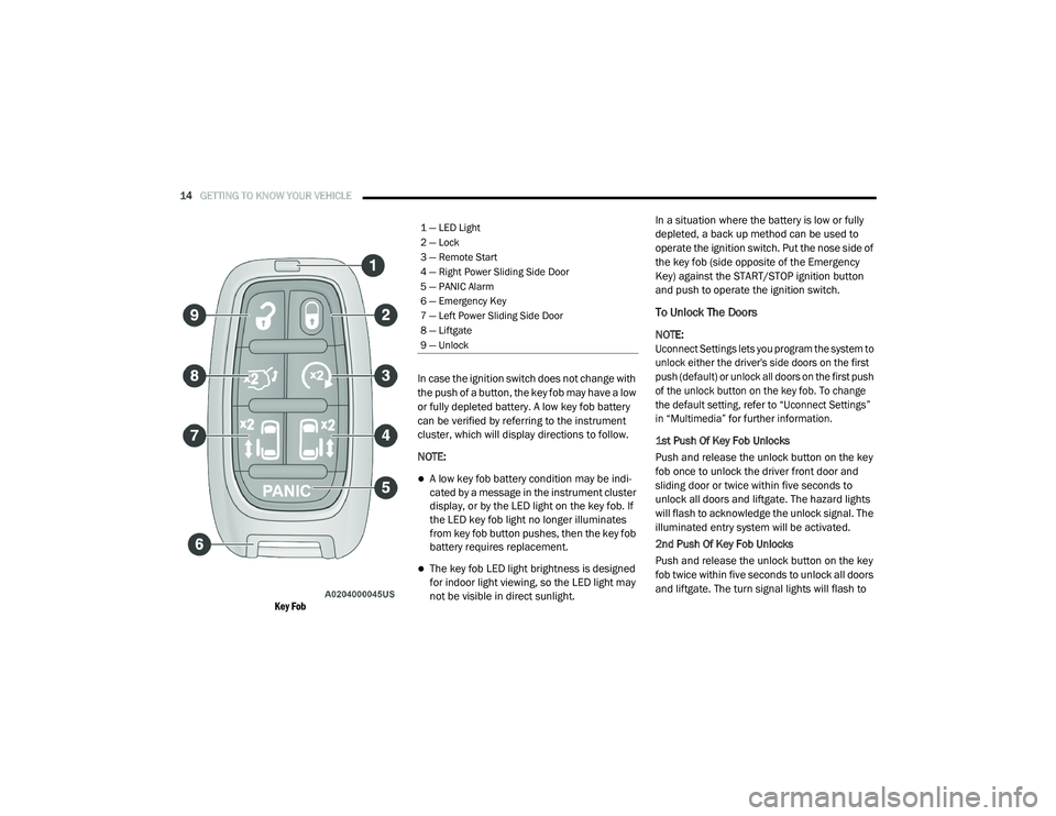
Key Fob
In case the ignition switch does not change with
the push of a button, the key fob may have a low
or fully depleted battery. A low key fob battery
can be verified by referring to the instrument
cluster, which will display directions to follow.
NOTE:
A low key fob battery condition may be indi
-
cated by a message in the instrument cluster
display, or by the LED light on the key fob. If
the LED key fob light no longer illuminates
from key fob button pushes, then the key fob
battery requires replacement.
The key fob LED light brightness is designed
for indoor light viewing, so the LED light may
not be visible in direct sunlight. In a situation where the battery is low or fully
depleted, a back up method can be used to
operate the ignition switch. Put the nose side of
the key fob (side opposite of the Emergency
Key) against the START/STOP ignition button
and push to operate the ignition switch.
To Unlock The Doors
NOTE:
Uconnect Settings lets you program the system to
unlock either the driver's side doors on the first
push (default) or unlock all doors on the first push
of the unlock button on the key fob. To change
the default setting, refer to “Uconnect Settings”
in “Multimedia” for further information.
1st Push Of Key Fob Unlocks
Push and release the unlock button on the key
fob once to unlock the driver front door and
sliding door or twice within five seconds to
unlock all doors and liftgate. The hazard lights
will flash to acknowledge the unlock signal. The
illuminated entry system will be activated.
2nd Push Of Key Fob Unlocks
Push and release the unlock button on the key
fob twice within five seconds to unlock all doors
and liftgate. The turn signal lights will flash to
1 — LED Light
2 — Lock
3 — Remote Start
4 — Right Power Sliding Side Door
5 — PANIC Alarm
6 — Emergency Key
7 — Left Power Sliding Side Door
8 — Liftgate
9 — Unlock
20_RU_OM_EN_US_t.book Page 14
Page 20 of 516
18GETTING TO KNOW YOUR VEHICLE
General Information
The following regulatory statement applies to all
Radio Frequency (RF) devices equipped in this
vehicle:
This device complies with Part 15 of the FCC
Rules and with Innovation, Science and
Economic Development Canada license-exempt
RSS standard(s). Operation is subject to the
following two conditions:
1. This device may not cause harmful
interference, and
2. This device must accept any interference received, including interference that may
cause undesired operation.
Le présent appareil est conforme aux CNR
d`Innovation, Science and Economic
Development applicables aux appareils radio
exempts de licence. L'exploitation est autorisée
aux deux conditions suivantes:
1. l'appareil ne doit pas produire de brouillage, et
2. l'utilisateur de l'appareil doit accepter tout brouillage radioélectrique subi, même si le
brouillage est susceptible d'en compro -
mettre le fonctionnement. La operación de este equipo está sujeta a las
siguientes dos condiciones:
1. es posible que este equipo o dispositivo no
cause interferencia perjudicial y
2. este equipo o dispositivo debe aceptar cualquier interferencia, incluyendo la que
pueda causar su operación no deseada.
NOTE:
Changes or modifications not expressly
approved by the party responsible for compli -
ance could void the user’s authority to operate
the equipment.
IGNITION SWITCH
Keyless Enter-N-Go — Ignition
If applicable, refer to the “Hybrid Supplement”
for additional information.
This feature allows the driver to start the vehicle
with the push of a button, as long as the key fob
is in the passenger compartment, and the
drivers foot is on the brake pedal.
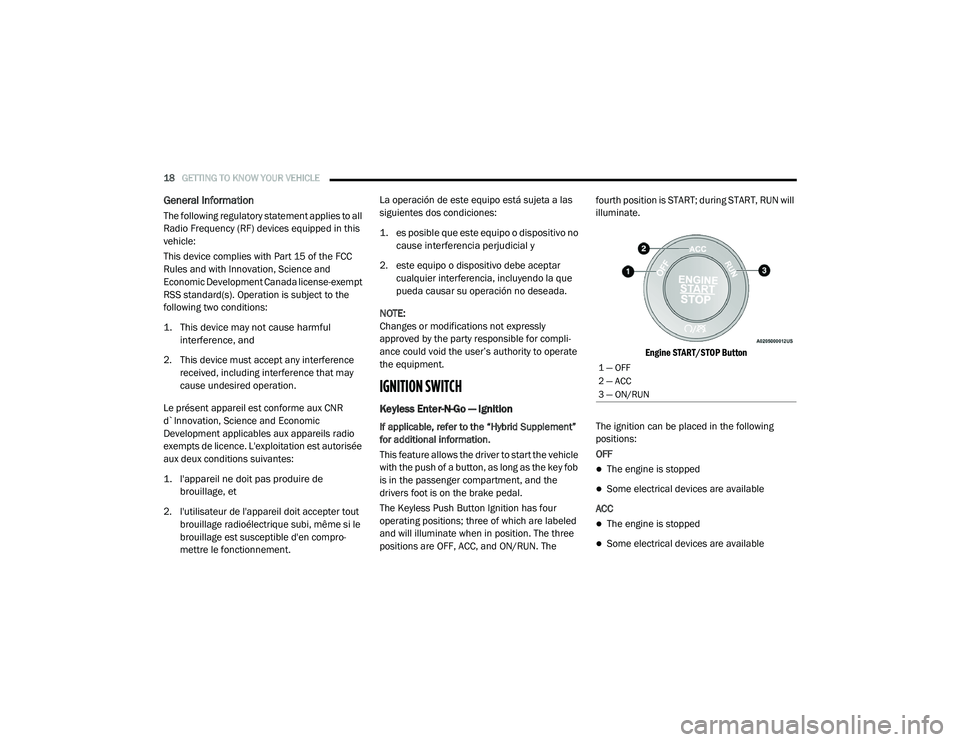
The Keyless Push Button Ignition has four
operating positions; three of which are labeled
and will illuminate when in position. The three
positions are OFF, ACC, and ON/RUN. The fourth position is START; during START, RUN will
illuminate.
Engine START/STOP Button
The ignition can be placed in the following
positions:
OFF
The engine is stopped
Some electrical devices are available
ACC
The engine is stopped
Some electrical devices are available
1 — OFF
2 — ACC
3 — ON/RUN
20_RU_OM_EN_US_t.book Page 18
Page 21 of 516
GETTING TO KNOW YOUR VEHICLE19
(Continued)
ON/RUN
Driving position
All the electrical devices are available
START
Start the vehicle
The engine only runs in the ON/RUN ignition
position or from a remote start request.
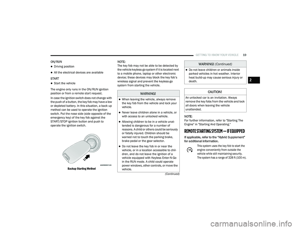
In case the ignition switch does not change with
the push of a button, the key fob may have a low
or depleted battery. In this situation, a back up
method can be used to operate the ignition
switch. Put the nose side (side opposite of the
emergency key) of the key fob against the
START/STOP ignition button and push to
operate the ignition switch.
Backup Starting Method
NOTE:
The key fob may not be able to be detected by
the vehicle keyless-go system if it is located next
to a mobile phone, laptop or other electronic
device; these devices may block the key fob’s
wireless signal and prevent the keyless-go
system from starting the vehicle.
NOTE:
For further information, refer to "Starting The
Engine" in "Starting And Operating."
REMOTE STARTING SYSTEM — IF EQUIPPED
If applicable, refer to the “Hybrid Supplement”
for additional information.
This system uses the key fob to start the
engine conveniently from outside the
vehicle while still maintaining security.
The system has a range of 328 ft (100 m).
WARNING!
When leaving the vehicle, always remove
the key fob from the vehicle and lock your
vehicle.
Never leave children alone in a vehicle, or
with access to an unlocked vehicle.
Allowing children to be in a vehicle unat -
tended is dangerous for a number of
reasons. A child or others could be seriously
or fatally injured. Children should be
warned not to touch the parking brake,
brake pedal or the gear selector.
Do not leave the key fob in or near the
vehicle, or in a location accessible to chil-
dren, and do not leave the ignition of a
vehicle equipped with Keyless Enter-N-Go
in the RUN mode. A child could operate
power windows, other controls, or move the
vehicle.
Do not leave children or animals inside
parked vehicles in hot weather. Interior
heat build-up may cause serious injury or
death.
CAUTION!
An unlocked car is an invitation. Always
remove the key fobs from the vehicle and lock
all doors when leaving the vehicle
unattended.
WARNING! (Continued)
2
20_RU_OM_EN_US_t.book Page 19
Page 22 of 516
20GETTING TO KNOW YOUR VEHICLE
The Remote Starting System also activates the
Climate Control, vented seats (if equipped) in
temperatures above 80°F (26.7°C), and the
optional heated seats, and optional heated
steering wheel in temperatures below 40°F
(4.4°C).
NOTE:
The vehicle must be equipped with an auto -
matic transmission to be equipped with
Remote Start.
Obstructions between the vehicle and key
fob may reduce this range.
How To Use Remote Start
If applicable, refer to the “Hybrid Supplement”
for additional information.
Push Remote Start button on the key fob twice
within five seconds. Pushing the Remote Start
button a third time shuts the engine off.
To drive the vehicle, push the unlock button,
and place the ignition in the ON/RUN position.
With remote start, the engine will only run for
15 minutes (timeout) unless the ignition key
is placed in the ON/RUN position.
The vehicle must be started with the key after
two consecutive timeouts.
All of the following conditions must be met
before the engine will remote start:
Gear selector in PARK
Doors closed
Hood closed
Liftgate closed
Hazard switch off
Brake switch inactive (brake pedal not
pushed)
Battery at an acceptable charge level
Key fob PANIC button not pushed
System not disabled from previous remote
start event
Vehicle alarm system indicator flashing
Ignition in STOP/OFF position
Fuel level meets minimum requirement
Malfunction Indicator Light is not illuminated
Remote Start Cancel Message — If Equipped
The following messages will display in the
instrument cluster if the vehicle fails to remote
start or exits remote start prematurely:
Remote Start Cancelled — Door Open
Remote Start Cancelled — Hood Open
Remote Start Cancelled — Fuel Low
Remote Start Cancelled — Liftgate Open
WARNING!
Do not start or run an engine in a closed
garage or confined area. Exhaust gas
contains Carbon Monoxide (CO) which is
odorless and colorless. Carbon Monoxide is
poisonous and can cause serious injury or
death when inhaled.
Keep key fobs away from children. Opera -
tion of the Remote Start System, windows,
door locks or other controls could cause
serious injury or death.
20_RU_OM_EN_US_t.book Page 20
Page 23 of 516
GETTING TO KNOW YOUR VEHICLE21
Remote Start Cancelled — Too Cold
Remote Start Cancelled — Time Expired
Remote Start Disabled — Start Vehicle To
Reset
The message will stay active until the ignition is
placed in the ON/RUN position.
To Enter Remote Start Mode
If applicable, refer to the “Hybrid Supplement”
for additional information.
Push and release the Remote Start button on
the key fob twice within five seconds. The
vehicle doors will lock, the turn signals will flash
twice, and the horn will chirp twice. Then the
engine will start, and the vehicle will remain in
the Remote Start mode for a 15 minute cycle.
NOTE:
If an engine fault is present or fuel level is
low, the vehicle will start and then shut down
in 10 seconds.
The park lamps will turn on and remain on
during Remote Start mode.
For security, power window operation is
disabled when the vehicle is in the Remote
Start mode.
The engine can be started two consecutive
times (two 15 minute cycles) with the key
fob. However, the ignition must be placed in
the ON/RUN position before you can repeat
the start sequence for a third cycle.
To Exit Remote Start Mode Without Driving
The Vehicle
If applicable, refer to the “Hybrid Supplement”
for additional information.
Push and release the Remote Start button one
time or allow the remote start cycle to complete
the entire 15 minute cycle.
NOTE:
To avoid unintentional shutdowns, the system
will disable for two seconds after receiving a
valid Remote Start request.
To Exit Remote Start Mode And Drive The
Vehicle
Before the end of 15 minute cycle, push and
release the unlock button on the key fob to
unlock the doors, or unlock the vehicle using
Keyless Enter-N-Go — Passive Entry via the door handles, and disarm the vehicle security alarm
(if equipped). Then, prior to the end of the
15 minute cycle, push and release the START/
STOP ignition button.
NOTE:
For vehicles equipped with the Keyless
Enter-N-Go — Passive Entry feature, the
message “Remote Start Active — Push Start
Button” will display in the instrument cluster
display until you push the START/STOP ignition
button.
Remote Start Comfort Systems — If
Equipped
When Remote Start is activated, the Climate
Control, vented seats (if equipped) are also
activated in temperatures above 80°F
(26.7°C), and the optional heated seats, and
optional heated steering wheel in temperatures
below 40°F (4.4°C). These features will stay on
through the duration of Remote Start, or until
the ignition switch is placed in the ON/RUN
position.
2
20_RU_OM_EN_US_t.book Page 21
Page 26 of 516
24GETTING TO KNOW YOUR VEHICLE
VEHICLE SECURITY ALARM — IF EQUIPPED
The vehicle security alarm monitors the vehicle
doors for unauthorized entry and the ignition
switch for unauthorized operation. When the
alarm is activated, the interior switches for door
locks, power sliding doors and power liftgate
are disabled. The vehicle security alarm
provides both audible and visible signals. If
something triggers the alarm, the vehicle
security alarm will provide the following audible
and visible signals: the horn will pulse, the park
lamps and/or turn signals will flash, and the
vehicle security light in the instrument cluster
will flash.
To Arm The System
Follow these steps to arm the vehicle security
alarm:
1. Make sure the vehicle’s ignition is placed
in the OFF position. Refer to "Starting The
Engine" in "Starting And Operating" for
further information.
For vehicles equipped with Keyless
Enter-N-Go — Passive Entry, make sure
the vehicle ignition system is OFF. 2. Perform one of the following methods to
lock the vehicle:
Push lock on the interior power door lock
switch with the driver and/or passenger
door open.
Push the lock button on the exterior
Passive Entry Door Handle with a valid
key fob available in the same exterior
zone. Refer to "Keyless Enter-N-Go —
Passive Entry" in “Doors” in this chapter
for further information.
Push the lock button on the key fob.
3. If any doors are open, close them.
To Disarm The System
The vehicle security alarm can be disarmed
using any of the following methods:
Push the unlock button on the key fob.
Grasp the Passive Entry Unlock Door Handle
(if equipped). Refer to "Keyless Enter-N-Go —
Passive Entry" in “Doors” in this chapter for
further information.
Hands Free Liftgate Passive Entry activation
(if equipped).
Cycle the vehicle ignition system out of the
OFF position.
For vehicles equipped with Keyless
Enter-N-Go — Passive Entry, push the
keyless ignition START/STOP ignition
button (requires at least one valid key fob
in the vehicle).
NOTE:
The driver's door key cylinder and the liftgate
button on the key fob cannot arm or disarm
the vehicle security alarm.
The vehicle security alarm remains armed
during power liftgate entry. Pushing the lift -
gate button will not disarm the vehicle secu -
rity alarm. If someone enters the vehicle
through the liftgate and opens any door, the
alarm will sound.
When the vehicle security alarm is armed,
the interior power door lock switches will not
unlock the doors.
20_RU_OM_EN_US_t.book Page 24
Page 46 of 516
44GETTING TO KNOW YOUR VEHICLE
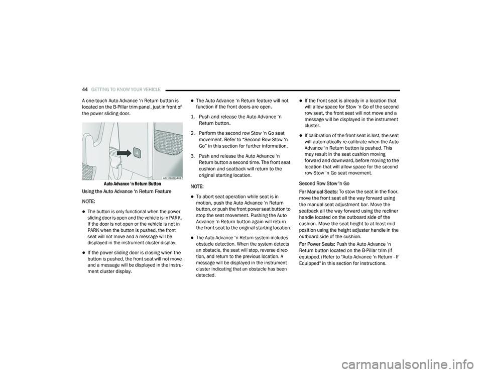
A one-touch Auto Advance ‘n Return button is
located on the B-Pillar trim panel, just in front of
the power sliding door.
Auto Advance ‘n Return Button
Using the Auto Advance ‘n Return Feature
NOTE:
The button is only functional when the power
sliding door is open and the vehicle is in PARK.
If the door is not open or the vehicle is not in
PARK when the button is pushed, the front
seat will not move and a message will be
displayed in the instrument cluster display.
If the power sliding door is closing when the
button is pushed, the front seat will not move
and a message will be displayed in the instru -
ment cluster display.
The Auto Advance ‘n Return feature will not
function if the front doors are open.
1. Push and release the Auto Advance ‘n Return button.
2. Perform the second row Stow ‘n Go seat movement. Refer to “Second Row Stow ‘n
Go” in this section for further information.
3. Push and release the Auto Advance ‘n Return button a second time. The front seat
cushion and seatback will return to the
original starting location.
NOTE:
To abort seat operation while seat is in
motion, push the Auto Advance ‘n Return
button, or push the front power seat button to
stop the seat movement. Pushing the Auto
Advance ‘n Return button again will return
the front seat to the original starting location.
The Auto Advance ‘n Return system includes
obstacle detection. When the system detects
an obstacle, the seat will stop, reverse direc -
tion, and return to the previous location. A
message will be displayed in the instrument
cluster indicating that an obstacle has been
detected.
If the front seat is already in a location that
will allow space for Stow ‘n Go of the second
row seat, the front seat will not move and a
message will be displayed in the instrument
cluster.
If calibration of the front seat is lost, the seat
will automatically re-calibrate when the Auto
Advance ‘n Return button is pushed. This
may result in the seat cushion moving
forward and downward, before moving to the
location that will allow space for the second
row Stow ‘n Go seat movement.
Second Row Stow 'n Go
For Manual Seats: To stow the seat in the floor,
move the front seat all the way forward using
the manual seat adjustment bar. Move the
seatback all the way forward using the recliner
handle located on the outboard side of the
cushion. Move the seat height to at least mid
position using the height adjuster handle in the
outboard side of the cushion.
For Power Seats: Push the Auto Advance ‘n
Return button located on the B-Pillar trim (if
equipped.) Refer to "Auto Advance ‘n Return - If
Equipped" in this section for instructions.
20_RU_OM_EN_US_t.book Page 44
Page 109 of 516
GETTING TO KNOW YOUR VEHICLE107
5. When finished, push power button to turn
vacuum off and store vacuum hose and any
attachments.
6. Before exiting the vehicle:
If the ignition is in the ACC position, push
the START/STOP ignition button to place
ignition in the OFF position, remove key
fob from the vehicle, and lock the vehicle.
If the engine is running, raise all of the
windows, push the START/STOP ignition
button to place ignition in the OFF posi -tion, remove key fob from the vehicle,
close all of the doors and the liftgate and
lock the vehicle.
Vacuum Troubleshooting
DO NOT use with any opening blocked. If an
object becomes lodged in the hose, attempt
to fully extend the hose in a straight line while
the vacuum motor is running. If this does not
dislodge the object, turn the vacuum OFF and
remove the hose from the vehicle following
the removal instructions below. If the filter is
clogged, follow the emptying debris bin
procedure and lightly tap the filter on the
collection bin to remove any collected debris
from the filter. Both the bin and the filter can
be rinsed with water if needed. To avoid mold
and stale odors, allow both to dry completely
before reinstalling in your vehicle. If the filter
has tears, holes or other damage and needs
to be replaced, please contact an authorized
dealer.
If there are any other issues with your
vacuum, contact an authorized dealer. Your
vacuum has no user serviceable parts. Debris Bin
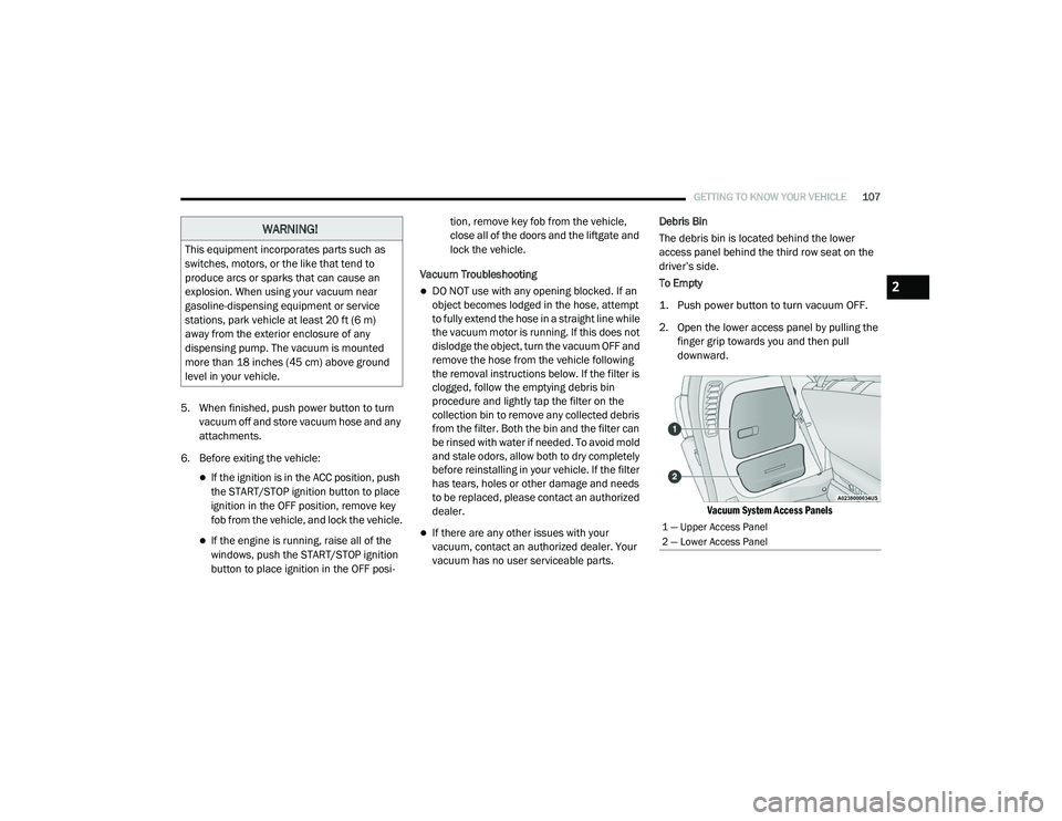
The debris bin is located behind the lower
access panel behind the third row seat on the
driver’s side.
To Empty
1. Push power button to turn vacuum OFF.
2. Open the lower access panel by pulling the
finger grip towards you and then pull
downward.
Vacuum System Access Panels
WARNING!
This equipment incorporates parts such as
switches, motors, or the like that tend to
produce arcs or sparks that can cause an
explosion. When using your vacuum near
gasoline-dispensing equipment or service
stations, park vehicle at least 20 ft (6 m)
away from the exterior enclosure of any
dispensing pump. The vacuum is mounted
more than 18 inches (45 cm) above ground
level in your vehicle.
1 — Upper Access Panel
2 — Lower Access Panel
2
20_RU_OM_EN_US_t.book Page 107