start stop button CHRYSLER PACIFICA 2021 Owners Manual
[x] Cancel search | Manufacturer: CHRYSLER, Model Year: 2021, Model line: PACIFICA, Model: CHRYSLER PACIFICA 2021Pages: 401, PDF Size: 26.88 MB
Page 6 of 401
4
LIFTGATE ................................................................. 98 To Unlock/Open The Liftgate...........................98
To Lock/Close The Liftgate ..............................98
Power Liftgate — If Equipped ...........................98
Hands-Free Liftgate — If Equipped ............... 100
Cargo Area Features ..................................... 101
STOW ‘N PLACE ROOF RACK —
IF EQUIPPED ........................................................ 106
Deploying The Crossbars .............................. 107Stowing The Crossbars ................................. 108
GETTING TO KNOW YOUR
INSTRUMENT PANEL
INSTRUMENT CLUSTER....................................... 110
Instrument Cluster Descriptions .................. 112
INSTRUMENT CLUSTER DISPLAY ...................... 112
Instrument Cluster Display Location And
Controls .......................................................... 113
Oil Life Reset ................................................. 114
KeySense Cluster Messages —
If Equipped..................................................... 115
Instrument Cluster Display Menu Items ..... 116
Battery Saver On/Battery Saver Mode
Message — Electrical Load Reduction
Actions — If Equipped.................................... 121 TRIP COMPUTER ................................................ 122
WARNING LIGHTS AND MESSAGES ................. 123
Red Warning Lights ....................................... 123
Yellow Warning Lights ................................... 126Yellow Indicator Lights .................................. 129
Green Indicator Lights .................................. 129
White Indicator Lights ................................... 130Blue Indicator Lights ..................................... 130
ONBOARD DIAGNOSTIC SYSTEM — OBD II...... 130
Onboard Diagnostic System
(OBD II) Cybersecurity ................................... 130
EMISSIONS INSPECTION AND MAINTENANCE
PROGRAMS ....................................................... 131STARTING AND OPERATING
STARTING THE ENGINE ...................................... 132
Normal Starting ............................................ 132
AutoPark ........................................................ 133Cold Weather Operation
(Below –22°F Or −30°C) ............................ 135
After Starting — Warming Up The Engine..... 135
If Engine Fails To Start ................................. 135
To Turn Off The Engine Using ENGINE
START/STOP Button ...................................... 136 ENGINE BLOCK HEATER — IF EQUIPPED .......... 136
ENGINE BREAK-IN RECOMMENDATIONS ........ 136
PARKING BRAKE ................................................. 137 Electric Park Brake (EPB) ............................ 137
AUTOMATIC TRANSMISSION ............................. 139
Ignition Park Interlock................................... 140
Brake/Transmission Shift Interlock
(BTSI) System ................................................ 141
9-Speed Automatic Transmission ............... 141
Gear Ranges .................................................. 141
ALL-WHEEL DRIVE (AWD) — IF EQUIPPED ...... 144
ACTIVE NOISE CANCELLATION .......................... 144
POWER STEERING............................................... 144
STOP/START SYSTEM — IF EQUIPPED ............. 145 Autostop Mode .............................................. 145
Possible Reasons The Engine Does Not
Autostop......................................................... 145
To Start The Engine While In Autostop ........ 146To Manually Turn Off The Stop/Start
System ........................................................... 146
To Manually Turn On The Stop/Start
System ........................................................... 147
System Malfunction ...................................... 147
21_RUP_OM_EN_USC_t.book Page 4
Page 19 of 401
GETTING TO KNOW YOUR VEHICLE17
Start Up Display Features
Unique splash screen graphic
Telltale illuminated
After unique splash screen, and after stored
messages are cycled, then start-up KeySense
messages (Range & Max Speed) are displayed
The following features are always enabled when
this key is in use:
Entertainment audio muted if front occupied
seat belts are not fastened
Consistent seat belt unfastened chime
Maximum radio volume limited to 15 out of 39
Daytime Running Lights
Headlights On With Wipers
Rain Sensing Wipers
Automatic High Beams
SENTRY KEY
The Sentry Key Immobilizer system prevents
unauthorized vehicle operation by disabling the
engine. The system does not need to be armed or
activated. Operation is automatic, regardless of
whether the vehicle is locked or unlocked. The system uses a key fob, keyless push button
ignition and a Radio Frequency (RF) receiver to
prevent unauthorized vehicle operation. Therefore,
only key fobs that are programmed to the vehicle
can be used to start and operate the vehicle. The
system cannot reprogram a key fob obtained from
another vehicle.
After placing the ignition switch in the ON/RUN
position, the Vehicle Security Light will turn on for
three seconds for a bulb check. If the light remains
on after the bulb check, it indicates that there is a
problem with the electronics. In addition, if the light
begins to flash after the bulb check, it indicates
that someone attempted to start the engine with
an invalid key fob. In the event that a valid key fob
is used to start the engine but there is an issue
with the vehicle electronics, the engine will start
and shut off after two seconds.
If the Vehicle Security Light turns on during normal
vehicle operation (vehicle running for longer than
10 seconds), it indicates that there is a fault in the
electronics. Should this occur, have the vehicle
serviced as soon as possible by an authorized
dealer.
All of the key fobs provided with your new vehicle
have been programmed to the vehicle electronics
Ú
page 387.
IGNITION SWITCH
KEYLESS ENTER ‘N GO™ IGNITION
If applicable, refer to the “Hybrid Supplement”
for additional information.
This feature allows the driver to operate the
ignition switch with the push of a button as long as
the key fob is in the passenger compartment.
The START/STOP ignition button has four
operating positions; three of which are labeled and
will illuminate when in position. The three positions
are OFF, ACC, and ON/RUN. The fourth position is
START. During START, RUN will illuminate.
CAUTION!
The Sentry Key Immobilizer system is not
compatible with some aftermarket Remote Start
systems. Use of these systems may result in
vehicle starting problems and loss of security
protection.
2
21_RUP_OM_EN_USC_t.book Page 17
Page 20 of 401
18GETTING TO KNOW YOUR VEHICLE
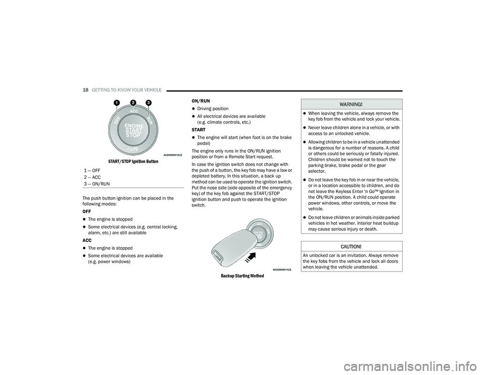
START/STOP Ignition Button
The push button ignition can be placed in the
following modes:
OFF
The engine is stopped
Some electrical devices (e.g. central locking,
alarm, etc.) are still available
ACC
The engine is stopped
Some electrical devices are available
(e.g. power windows) ON/RUN
Driving position
All electrical devices are available
(e.g. climate controls, etc.)
START
The engine will start (when foot is on the brake
pedal)
The engine only runs in the ON/RUN ignition
position or from a Remote Start request.
In case the ignition switch does not change with
the push of a button, the key fob may have a low or
depleted battery. In this situation, a back up
method can be used to operate the ignition switch.
Put the nose side (side opposite of the emergency
key) of the key fob against the START/STOP
ignition button and push to operate the ignition
switch.
Backup Starting Method
1 — OFF
2 — ACC
3 — ON/RUN
WARNING!
When leaving the vehicle, always remove the
key fob from the vehicle and lock your vehicle.
Never leave children alone in a vehicle, or with
access to an unlocked vehicle.
Allowing children to be in a vehicle unattended
is dangerous for a number of reasons. A child
or others could be seriously or fatally injured.
Children should be warned not to touch the
parking brake, brake pedal or the gear
selector.
Do not leave the key fob in or near the vehicle,
or in a location accessible to children, and do
not leave the Keyless Enter ‘n Go™ Ignition in
the ON/RUN position. A child could operate
power windows, other controls, or move the
vehicle.
Do not leave children or animals inside parked
vehicles in hot weather. Interior heat buildup
may cause serious injury or death.
CAUTION!
An unlocked car is an invitation. Always remove
the key fobs from the vehicle and lock all doors
when leaving the vehicle unattended.
21_RUP_OM_EN_USC_t.book Page 18
Page 22 of 401
20GETTING TO KNOW YOUR VEHICLE
All of the following conditions must be met before
the engine will Remote Start:
Gear selector in PARK
Doors closed
Hood closed
Liftgate closed
Hazard switch off
Brake switch inactive (brake pedal not pressed)
Battery at an acceptable charge level
PANIC button not pushed
System not disabled from previous Remote
Start event
Vehicle Security system indicator flashing
Ignition in OFF position
Fuel level meets minimum requirement
Vehicle Security system is not signaling an
intrusion
Malfunction Indicator Light (MIL) is not
illuminated
TO EXIT REMOTE START MODE
If applicable, refer to the “Hybrid Supplement”
for additional information.
To drive the vehicle after starting the Remote Start
system, either push and release the unlock button
on the key fob to unlock the doors, or unlock the
vehicle using Keyless Enter ‘n Go™ — Passive Entry
via the door handles, and disarm the Vehicle
Security system (if equipped). Then, prior to the
end of the 15 minute cycle, push and release the
START/STOP ignition button. The Remote Start system will turn the engine off if
the Remote Start button is pushed again, or if the
engine is allowed to run for the entire 15 minute
cycle. Once the ignition is placed in the ON/RUN
position, the climate controls will resume the
previously set operations (temperature, blower
control, etc.).
NOTE:
For vehicles equipped with the Keyless
Enter ‘n Go™ — Passive Entry feature, the
message “Remote Start Active — Push Start
Button” will show in the instrument cluster
display until you push the START/STOP ignition
button.
To avoid unintentional shutdowns, the system
will disable for two seconds after receiving a
valid Remote Start request.
REMOTE START FRONT DEFROST
A
CTIVATION — IF EQUIPPED
When Remote Start is active, and the outside
ambient temperature is 40°F (4.5°C) or below, the
system will automatically activate front defrost for
15 minutes or less. The time is dependent on the
ambient temperature. Once the timer expires, the
system will automatically adjust the settings
depending on ambient conditions. See “Remote
Start Comfort Systems — If Equipped” in the next
section for detailed operation.
WARNING!
Do not start or run an engine in a closed
garage or confined area. Exhaust gas contains
Carbon Monoxide (CO) which is odorless and
colorless. Carbon Monoxide is poisonous and
can cause serious injury or death when
inhaled.
Keep key fobs away from children. Operation
of the Remote Start system, windows, door
locks or other controls could cause serious
injury or death.
21_RUP_OM_EN_USC_t.book Page 20
Page 24 of 401
22GETTING TO KNOW YOUR VEHICLE
TO ARM THE SYSTEM
Follow these steps to arm the Vehicle Security
system:
1. Make sure the vehicle’s ignition is placed in
the OFF position
Ú
page 132.
For vehicles equipped with Keyless Enter ‘n
Go™— Passive Entry, make sure the vehicle
ignition system is OFF.
2. Perform one of the following methods to lock the vehicle:
Push lock on the interior power door lock
switch with the driver and/or passenger
door open.
Push the lock button on the exterior Passive
Entry door handle with a valid key fob avail -
able in the same exterior zone Ú page 24.
Push the lock button on the key fob.
3. If any doors are open, close them.
TO DISARM THE SYSTEM
The Vehicle Security system can be disarmed using
any of the following methods:
Push the unlock button on the key fob.
Grab the Passive Entry door handle (if equipped)
Ú page 24.
Hands-Free Liftgate Passive Entry activation
(if equipped).
Cycle the vehicle ignition system out of the OFF
position.
For vehicles equipped with Keyless Enter ‘n
Go™ — Passive Entry, push the keyless igni -
tion START/STOP ignition button (requires
at least one valid key fob in the vehicle).
NOTE:
The driver's door key cylinder and the liftgate
button on the key fob cannot arm or disarm the
Vehicle Security system.
The Vehicle Security system remains armed
during power liftgate entry. Pushing the liftgate
button will not disarm the Vehicle Security
system. If someone enters the vehicle through
the liftgate and opens any door, the alarm will
sound.
When the Vehicle Security system is armed, the
interior power door lock switches will not unlock
the doors. The Vehicle Security system is designed to protect
your vehicle. However, you can create conditions
where the system will give you a false alarm. If one
of the previously described arming sequences has
occurred, the Vehicle Security system will arm
regardless of whether you are in the vehicle or not.
If you remain in the vehicle and open a door, the
alarm will sound. If this occurs, disarm the Vehicle
Security system.
If the Vehicle Security system is armed and the
battery becomes disconnected, the Vehicle
Security system will remain armed when the
battery is reconnected; the exterior lights will flash,
and the horn will sound. If this occurs, disarm the
Vehicle Security system.
REARMING OF THE SYSTEM
If something triggers the alarm and no action is
taken to disarm it, the Vehicle Security system will
turn the horn off after a 29 second cycle (with 5
seconds between cycles and up to 8 cycles if the
trigger remains active) and then rearm itself.
21_RUP_OM_EN_USC_t.book Page 22
Page 45 of 401
GETTING TO KNOW YOUR VEHICLE43
1. Push and release the Auto Advance ‘n Return button.
2. Perform the second row Stow ‘n Go seat movement. Refer to “Second Row Stow ‘n Go”
in this section for further information.
3. Push and release the Auto Advance ‘n Return button a second time. The front seat cushion
and seatback will return to the original starting
location.
NOTE:
To abort seat operation while seat is in motion,
push the Auto Advance ‘n Return button, or
push the front power seat button to stop the
seat movement. Pushing the Auto Advance ‘n
Return button again will return the front seat to
the original starting location.
The Auto Advance ‘n Return system includes
obstacle detection. When the system detects an
obstacle, the seat will stop, reverse direction,
and return to the previous location. A message
will be displayed in the instrument cluster indi -
cating that an obstacle has been detected.
If the front seat is already in a location that will
allow space for Stow ‘n Go of the second row
seat, the front seat will not move and a message
will be displayed in the instrument cluster.
If calibration of the front seat is lost, the seat will
automatically recalibrate when the Auto
Advance ‘n Return button is pushed. This may
result in the seat cushion moving forward and
downward, before moving to the location that
will allow space for the second row Stow ‘n Go
seat movement.
SECOND ROW STOW 'N GO
For Manual Seats: To stow the seat in the floor,
move the front seat all the way forward using the
manual seat adjustment bar. Move the seatback
all the way forward using the recliner handle
located on the outboard side of the cushion. Move
the seat height to at least mid position using the
height adjuster handle in the outboard side of the
cushion.
For Power Seats: Push the Auto Advance ‘n Return
button located on the B-pillar trim (if equipped)
Ú page 42.
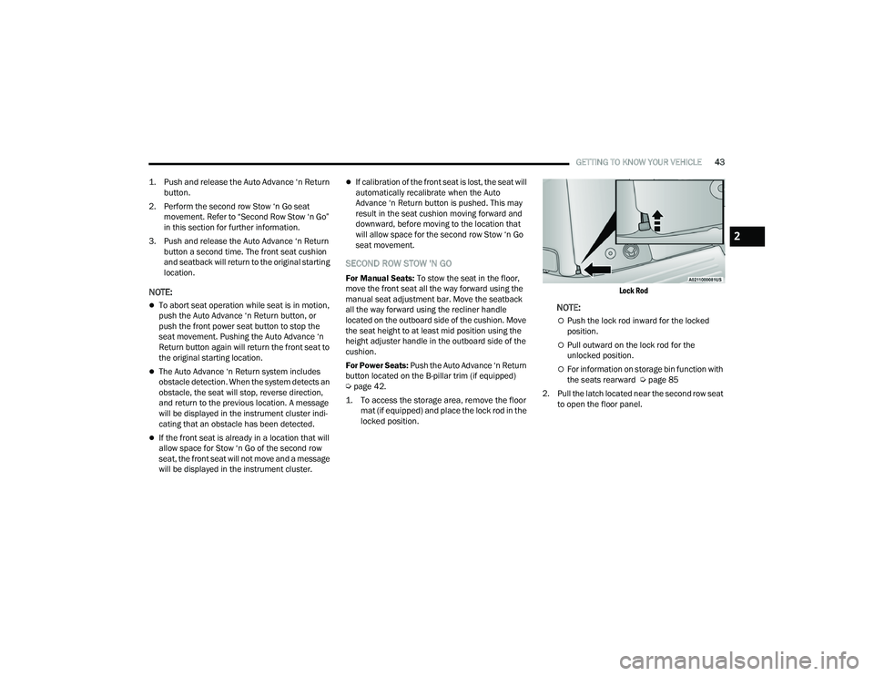
1. To access the storage area, remove the floor mat (if equipped) and place the lock rod in the
locked position.
Lock Rod
NOTE:
Push the lock rod inward for the locked
position.
Pull outward on the lock rod for the
unlocked position.
For information on storage bin function with
the seats rearward Ú
page 85
2. Pull the latch located near the second row seat to open the floor panel.
2
21_RUP_OM_EN_USC_t.book Page 43
Page 53 of 401
GETTING TO KNOW YOUR VEHICLE51
3. To abort seat operation while seat is in motion, push a different seat position selector switch
to stop the seat. Once the seat stops moving,
then the desired position can be selected.
4. The third row power seat system includes obstacle detection. When the system detects
an obstacle, the motors will stop and reverse
direction. Should this occur, remove the
obstacle before pushing the button again.
HEATED SEATS
Front Heated Seats — If Equipped
The front heated seats control buttons are located
in the touchscreen.
You can choose from HI, LO or off heat settings.
The indicator lights in each switch indicate the
level of heat in use. Two indicator lights will
illuminate for HI, one for LO and none for off.
Press the heated seat button once to turn
the HI setting on.
Press the heated seat button a second time
to turn the LO setting on.
Press the heated seat button a third time to
turn the heating elements off.
The level of heat selected will stay on until the
operator changes it.
NOTE:
Once a heat setting is selected, heat will be felt
within two to five minutes.
The engine must be running for the heated
seats to operate.
For information on use with the Remote Start
system, see Ú page 21.
Rear Heated Seats — If Equipped
On some models, the second row seats are
equipped with heaters. There are two heated seat
switches that allow the second row passengers to
operate the seats independently. The heated seat
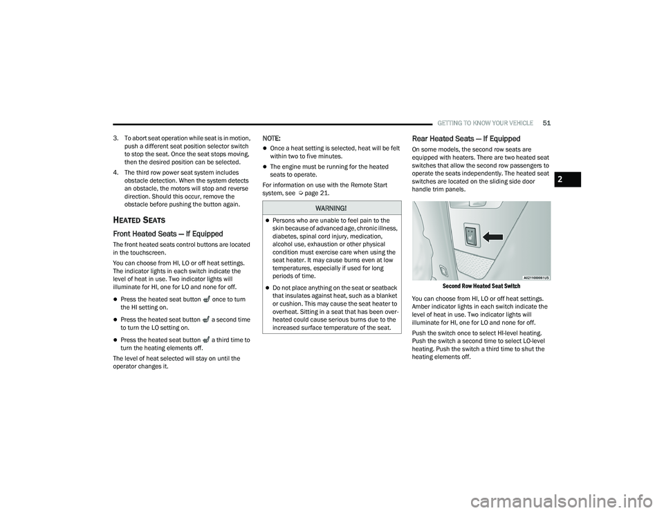
switches are located on the sliding side door
handle trim panels.
Second Row Heated Seat Switch
You can choose from HI, LO or off heat settings.
Amber indicator lights in each switch indicate the
level of heat in use. Two indicator lights will
illuminate for HI, one for LO and none for off.
Push the switch once to select HI-level heating.
Push the switch a second time to select LO-level
heating. Push the switch a third time to shut the
heating elements off.
WARNING!
Persons who are unable to feel pain to the
skin because of advanced age, chronic illness,
diabetes, spinal cord injury, medication,
alcohol use, exhaustion or other physical
condition must exercise care when using the
seat heater. It may cause burns even at low
temperatures, especially if used for long
periods of time.
Do not place anything on the seat or seatback
that insulates against heat, such as a blanket
or cushion. This may cause the seat heater to
overheat. Sitting in a seat that has been over -
heated could cause serious burns due to the
increased surface temperature of the seat.
2
21_RUP_OM_EN_USC_t.book Page 51
Page 58 of 401
56GETTING TO KNOW YOUR VEHICLE
UCONNECT VOICE RECOGNITION —
IF EQUIPPED
INTRODUCING VOICE RECOGNITION
Start using Uconnect Voice Recognition (VR) with
these helpful quick tips. It provides the key Voice
Commands and tips you need to know to control
your system.
The Uconnect 5 NAV with 10.1-inch display is
equipped with Voice Recognition. If you see the
NAV icon on the bottom bar or in the Apps menus
of your 10.1-inch touchscreen, you have the
Uconnect 5 NAV system. If not, you have a
Uconnect 5 with 10.1-inch display system.
BASIC VOICE COMMANDS
The basic Voice Commands below can be given at
any point while using your Uconnect system.
Push the VR button . After the beep, say:
“Cancel ” to stop a current voice session.
“Help ” to hear a list of suggested Voice
Commands.
“ Repeat ” to listen to the system prompts again.
Notice the visual cues that inform you of your Voice
Recognition system’s status.
GET STARTED
The VR button is used to activate/deactivate
your Voice Recognition system.
Helpful hints for using Voice Recognition:
Reduce background noise. Wind noise and
passenger conversations are examples of noise
that may impact recognition.
Speak clearly at a normal pace and volume
while facing straight ahead.
Each time you give a Voice Command, first push
the VR button, wait until after the beep, then say
your Voice Command. You can also say the
vehicle “Wake Up” word and state your
command.
A passenger can press the VR button shortcut
on the radio status bar to also issue a
command.
You can interrupt the help message or system
prompts by pushing the VR button and saying a
Voice Command or saying the vehicle’s “Wake
Up” word and saying a command from the
current category.
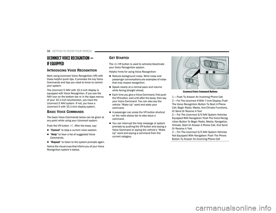
Uconnect Voice Command Buttons
1 — Push To Answer An Incoming Phone Call
2 — For The Uconnect 4 With 7-inch Display: Push
The Voice Recognition Button To Start A Phone
Call, Begin Radio, Media, And Climate Functions,
Or Send Or Receive A Text
2 — For The Uconnect 5/5 NAV System Vehicles
Equipped With Navigation: Push The Voice Recog
-
nition Button To Begin Radio, Media, Navigation,
Climate, Start Or Answer A Phone Call, And Send
Or Receive A Text
2 — For The Uconnect 5/5 NAV System Vehicles
Not Equipped With Navigation: Push The Phone
Button To Answer An Incoming Phone Call
21_RUP_OM_EN_USC_t.book Page 56
Page 107 of 401
GETTING TO KNOW YOUR VEHICLE105
5. When finished, push power button to turn vacuum off and store vacuum hose and any
attachments.
6. Before exiting the vehicle:
If the ignition is in the ACC position, push
the START/STOP ignition button to place
ignition in the OFF position, remove key fob
from the vehicle, and lock the vehicle.
If the engine is running, raise all of the
windows, push the START/STOP ignition
button to place ignition in the OFF position,
remove key fob from the vehicle, close all of
the doors and the liftgate and lock the
vehicle. Vacuum Troubleshooting
DO NOT use with any opening blocked. If an
object becomes lodged in the hose, attempt to
fully extend the hose in a straight line while the
vacuum motor is running. If this does not
dislodge the object, turn the vacuum OFF and
remove the hose from the vehicle following the
removal instructions below. If the filter is
clogged, follow the emptying debris bin proce
-
dure and lightly tap the filter on the collection
bin to remove any collected debris from the
filter. Both the bin and the filter can be rinsed
with water if needed. To avoid mold and stale
odors, allow both to dry completely before rein -
stalling in your vehicle. If the filter has tears,
holes or other damage and needs to be
replaced, please contact an authorized dealer.
If there are any other issues with your vacuum,
contact an authorized dealer. Your vacuum has
no user serviceable parts.
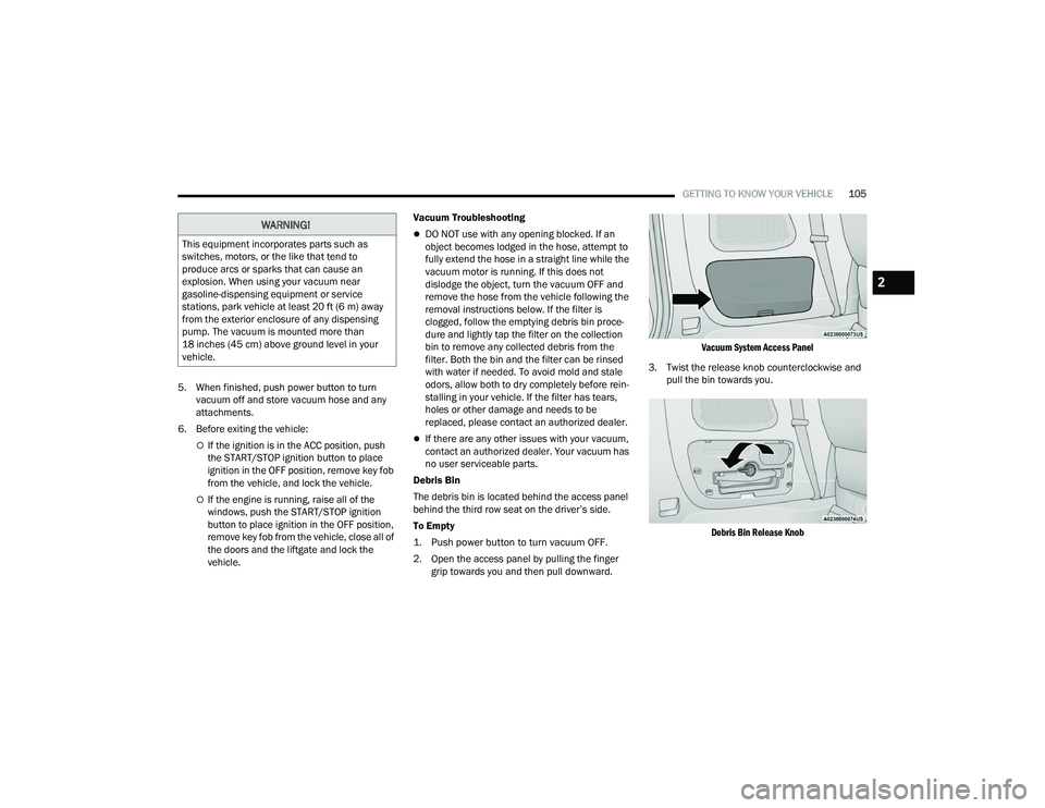
Debris Bin
The debris bin is located behind the access panel
behind the third row seat on the driver’s side.
To Empty
1. Push power button to turn vacuum OFF.
2. Open the access panel by pulling the finger grip towards you and then pull downward.
Vacuum System Access Panel
3. Twist the release knob counterclockwise and pull the bin towards you.
Debris Bin Release Knob
WARNING!
This equipment incorporates parts such as
switches, motors, or the like that tend to
produce arcs or sparks that can cause an
explosion. When using your vacuum near
gasoline-dispensing equipment or service
stations, park vehicle at least 20 ft (6 m) away
from the exterior enclosure of any dispensing
pump. The vacuum is mounted more than
18 inches (45 cm) above ground level in your
vehicle.
2
21_RUP_OM_EN_USC_t.book Page 105
Page 115 of 401
GETTING TO KNOW YOUR INSTRUMENT PANEL113
INSTRUMENT CLUSTER DISPLAY
L
OCATION AND CONTROLS
The vehicle’s instrument cluster is equipped with
an instrument cluster display (base or premium
cluster), which offers useful information to the
driver.
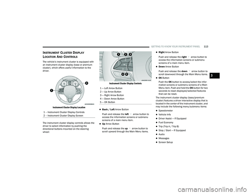
Instrument Cluster Display Location
The instrument cluster display controls allows the
driver to select information by pushing the
directional buttons mounted on the steering
wheel:
Instrument Cluster Display Controls
Back / Left
Arrow Button
Push and release the left arrow button to
access the information screens or submenu
screens of a main menu item.
Up Arrow Button
Push and release the up arrow button to
scroll upward through the Main Menu items.
Right Arrow Button
Push and release the right arrow button to
access the information screens or submenu
screens of a main menu item.
Down Arrow Button
Push and release the down arrow button to
scroll downward through the Main Menu items.
OK Button
Push the OK button to access/select the infor -
mation screens or submenu screens of a Main
Menu item. Push and hold the OK button for two
seconds to reset displayed/selected features
that can be reset.
The instrument cluster display (base/premium
cluster) features a driver interactive display that is
located in the center of the instrument cluster, and
may include the following menu/submenu items:
Speedometer
Vehicle Info
Driver Assist — If Equipped
Fuel Economy
Trip (Trip A / Trip B)
Stop / Start — If Equipped
Audio
Messages
Screen Setup
1 – Instrument Cluster Display Controls
2 – Instrument Cluster Display Screen
1 — Left Arrow Button
2 — Up Arrow Button
3 — Right Arrow Button
4 — Down Arrow Button
5 — OK Button
3
21_RUP_OM_EN_USC_t.book Page 113