fuel CHRYSLER PACIFICA 2021 Owners Manual
[x] Cancel search | Manufacturer: CHRYSLER, Model Year: 2021, Model line: PACIFICA, Model: CHRYSLER PACIFICA 2021Pages: 401, PDF Size: 26.88 MB
Page 7 of 401
5
CRUISE CONTROL SYSTEMS —
IF EQUIPPED ........................................................ 147 Cruise Control ................................................ 147
Adaptive Cruise Control (ACC) ..................... 149
PARKSENSE FRONT/REAR PARK ASSIST
SYSTEM — IF EQUIPPED ..................................... 158
ParkSense Sensors ....................................... 159
ParkSense Display ........................................ 159
ParkSense Warning Display.......................... 162
Enabling And Disabling ParkSense .............. 162
Service The ParkSense Park Assist
System ........................................................... 163Cleaning The ParkSense System ................. 163ParkSense System Usage Precautions ........ 163
PARKSENSE ACTIVE PARK ASSIST
SYSTEM — IF EQUIPPED ..................................... 164
Enabling And Disabling The ParkSense
Active Park Assist System ............................. 165
Parallel/Perpendicular Parking Space
Assistance Operation .................................... 166 LANESENSE — IF EQUIPPED .............................. 168
LaneSense Operation ................................... 168Turning LaneSense On Or Off ....................... 169
LaneSense Warning Message ...................... 169Changing LaneSense Status ........................ 171
PARKVIEW REAR BACK UP CAMERA............... 171
SURROUND VIEW CAMERA SYSTEM —
IF EQUIPPED ....................................................... 172
FAMCAM SYSTEM — IF EQUIPPED.................... 174
REFUELING THE VEHICLE ................................... 175
VEHICLE LOADING .............................................. 176 Certification Label ......................................... 176
TRAILER TOWING ............................................... 177
Common Towing Definitions......................... 177
Trailer Hitch Classification ............................ 179
Trailer Towing Weights
(Maximum Trailer Weight Ratings) ............ 179
Vehicle Loading Chart ................................... 180Trailer And Tongue Weight ........................... 182Towing Requirements .................................. 182
Towing Tips ................................................... 184 RECREATIONAL TOWING
(BEHIND MOTORHOME) ..................................... 185
Towing This Vehicle Behind Another
Vehicle ........................................................... 185
DRIVING TIPS ....................................................... 186
Driving On Slippery Surfaces ........................ 186Driving Through Water ................................. 187
MULTIMEDIA
UCONNECT SYSTEMS ......................................... 188
CYBERSECURITY ................................................. 188
UCONNECT SETTINGS ......................................... 189 Customer Programmable Features ............ 189
UCONNECT THEATER — UCONNECT 5/5
NAV WITH 10.1-INCH DISPLAY
(IF EQUIPPED) ..................................................... 214
Uconnect Theater Overview.......................... 214
Getting Started .............................................. 214
Accessing The System From The
Uconnect System .......................................... 214Uconnect Theater Controls ........................... 215
21_RUP_OM_EN_USC_t.book Page 5
Page 9 of 401
7
TIRE SERVICE KIT WITH A SUBWOOFER —
IF EQUIPPED ......................................................... 306
TIRE SERVICE KIT WITHOUT A
SUBWOOFER — IF EQUIPPED............................. 312
JUMP STARTING................................................... 318 Preparations For Jump Start......................... 318Jump Starting Procedure .............................. 319
REFUELING IN EMERGENCY –
IF EQUIPPED ......................................................... 320
IF YOUR ENGINE OVERHEATS ............................ 321
MANUAL PARK RELEASE ................................... 321
FREEING A STUCK VEHICLE ............................... 323
TOWING A DISABLED VEHICLE .......................... 324
All Wheel Drive (AWD) Models ...................... 326
ENHANCED ACCIDENT RESPONSE SYSTEM
(EARS) .................................................................. 326
EVENT DATA RECORDER (EDR) ......................... 326
SERVICING AND MAINTENANCE
SCHEDULED SERVICING ................................... 327
Maintenance Plan ......................................... 328
ENGINE COMPARTMENT .................................. 331
3.6L Engine ................................................... 331
Checking Oil Level ......................................... 332
Adding Washer Fluid .................................... 332
Maintenance-Free Battery ........................... 332Pressure Washing ......................................... 333
VEHICLE MAINTENANCE..................................... 333
Engine Oil ...................................................... 333
Engine Oil Filter ............................................. 334Engine Air Cleaner Filter ............................ 334
Accessory Drive Belt Inspection ................... 334Air Conditioner Maintenance........................ 335
Body Lubrication ........................................... 337Windshield Wiper Blades ............................. 337
Exhaust System ............................................ 341
Cooling System .............................................. 342
Brake System ............................................... 344
Automatic Transmission ............................... 345
Fuses.............................................................. 346
Bulb Replacement......................................... 354 TIRES .................................................................... 355
Tire Safety Information ................................. 355
Tires — General Information ........................ 363Tire Types....................................................... 367Spare Tires — If Equipped............................. 367Wheel And Wheel Trim Care ........................ 369Snow Traction Devices ................................. 370
Tire Rotation Recommendations ................. 372
DEPARTMENT OF TRANSPORTATION
UNIFORM TIRE QUALITY GRADES ..................... 372
Treadwear...................................................... 373
Traction Grades ............................................. 373Temperature Grades..................................... 373
STORING THE VEHICLE ....................................... 373
BODYWORK .......................................................... 374
Protection From Atmospheric Agents .......... 374
Body And Underbody Maintenance ............. 374
Preserving The Bodywork ............................. 374
INTERIORS ........................................................... 375
Seats And Fabric Parts ................................. 375
Plastic And Coated Parts .............................. 376
Leather Surfaces........................................... 376
Glass Surfaces ............................................. 376
21_RUP_OM_EN_USC_t.book Page 7
Page 10 of 401
8
TECHNICAL SPECIFICATIONS
VEHICLE IDENTIFICATION NUMBER (VIN)......... 377
BRAKE SYSTEM ................................................... 377
WHEEL AND TIRE TORQUE
SPECIFICATIONS .................................................. 377
Torque Specifications ................................... 377
FUEL REQUIREMENTS ........................................ 378
3.6L Engine.................................................... 378
Reformulated Gasoline ................................. 378Gasoline/Oxygenate Blends ......................... 379Do Not Use E-85 In Non-Flex Fuel
Vehicles .......................................................... 379
CNG And LP Fuel System Modifications ...... 379
Methylcyclopentadienyl Manganese
Tricarbonyl (MMT) In Gasoline...................... 379Materials Added To Fuel .............................. 380Fuel System Cautions ................................... 380
FLUID CAPACITIES ............................................... 381
ENGINE FLUIDS AND LUBRICANTS ................... 382
CHASSIS FLUIDS AND LUBRICANTS ................. 383
CUSTOMER ASSISTANCE
SUGGESTIONS FOR OBTAINING SERVICE
FOR YOUR VEHICLE ........................................... 384
Prepare For The Appointment ...................... 384Prepare A List ................................................ 384Be Reasonable With Requests..................... 384
IF YOU NEED ASSISTANCE ............................... 384
FCA US LLC Customer Center....................... 384
FCA Canada Inc. Customer Center............... 384
Mexico ............................................................ 385
Puerto Rico And US Virgin Islands................ 385
Customer Assistance For The Hearing
Or Speech Impaired
(TDD/TTY) ...................................................... 385
Service Contract ............................................ 385 WARRANTY INFORMATION ................................ 386
MOPAR® PARTS ................................................. 386
REPORTING SAFETY DEFECTS .......................... 386
In The 50 United States And
Washington, D.C............................................ 386
In Canada ...................................................... 386
PUBLICATION ORDER FORMS ........................... 387
GENERAL INFORMATION.................................... 387
21_RUP_OM_EN_USC_t.book Page 8
Page 14 of 401
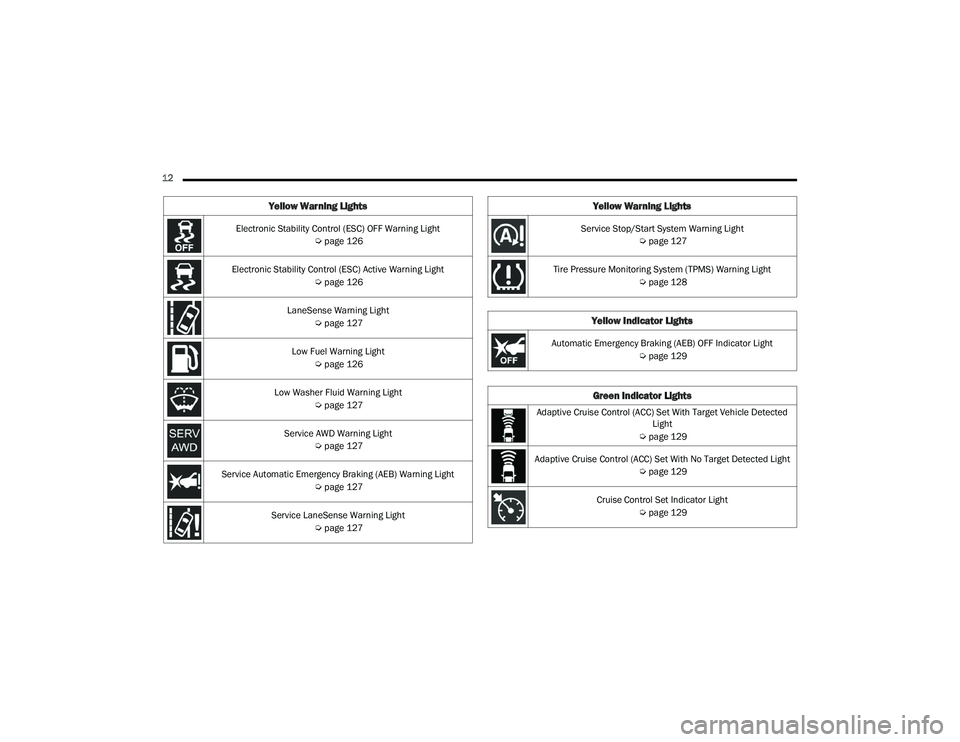
12 Electronic Stability Control (ESC) OFF Warning Light Úpage 126
Electronic Stability Control (ESC) Active Warning Light Úpage 126
LaneSense Warning Light Úpage 127
Low Fuel Warning Light Úpage 126
Low Washer Fluid Warning Light Úpage 127
Service AWD Warning Light Úpage 127
Service Automatic Emergency Braking (AEB) Warning Light Úpage 127
Service LaneSense Warning Light Úpage 127
Yellow Warning Lights
Service Stop/Start System Warning Light
Úpage 127
Tire Pressure Monitoring System (TPMS) Warning Light Úpage 128
Yellow Indicator Lights
Automatic Emergency Braking (AEB) OFF Indicator Light
Úpage 129
Green Indicator Lights
Adaptive Cruise Control (ACC) Set With Target Vehicle Detected
Light
Ú page 129
Adaptive Cruise Control (ACC) Set With No Target Detected Light Úpage 129
Cruise Control Set Indicator Light Úpage 129
Yellow Warning Lights
21_RUP_OM_EN_USC_t.book Page 12
Page 21 of 401
GETTING TO KNOW YOUR VEHICLE19
NOTE:
The key fob may not be detected by the vehicle
Keyless Enter ‘n Go™ system if it is located next
to a mobile phone, laptop or other electronic
device; these devices may block the key fob’s
wireless signal and prevent the Keyless Enter ‘n
Go™ system from starting the vehicle.
For the proper engine starting procedure, see
Úpage 132.
REMOTE START — IF EQUIPPED
If applicable, refer to the “Hybrid Supplement”
for additional information.
This system uses the key fob to start the
engine conveniently from outside the
vehicle while still maintaining security.
The system has a range of 328 ft
(100 m).
Remote Start is used to defrost windows in cold
weather and to reach a comfortable climate in all
ambient conditions before the customer enters the
vehicle.
NOTE:Obstructions between the vehicle and key fob may
reduce this range Ú page 387.
HOW TO USE REMOTE START
If applicable, refer to the “Hybrid Supplement”
for additional information.
Push and release the Remote Start button on the
key fob twice within five seconds. The vehicle
doors will lock, the parking lights will flash, and the
horn will chirp twice (if programmed). Then, the
engine will start, and the vehicle will remain in the
Remote Start mode for a 15 minute cycle.
Pushing the Remote Start button a third time shuts
the engine off. To drive the vehicle, push the unlock button, and
place the ignition in the ON/RUN position.
NOTE:
With Remote Start, the engine will only run for
15 minutes.
Remote Start can only be used twice.
If an engine fault is present or fuel level is
low, the vehicle will start and then shut down in
10 seconds.
The parking lights will turn on and remain on
during Remote Start mode.
For security, power window and power sunroof
operation (if equipped) are disabled when the
vehicle is in the Remote Start mode.
The ignition must be placed in the ON/RUN posi
-
tion before the Remote Start sequence can be
repeated for a third cycle.
WARNING!
Do not start or run an engine in a closed
garage or confined area. Exhaust gas contains
Carbon Monoxide (CO) which is odorless and
colorless. Carbon Monoxide is poisonous and
can cause serious injury or death when
inhaled.
Keep key fobs away from children. Operation
of the Remote Start system, windows, door
locks or other controls could cause serious
injury or death.
2
21_RUP_OM_EN_USC_t.book Page 19
Page 22 of 401
20GETTING TO KNOW YOUR VEHICLE
All of the following conditions must be met before
the engine will Remote Start:
Gear selector in PARK
Doors closed
Hood closed
Liftgate closed
Hazard switch off
Brake switch inactive (brake pedal not pressed)
Battery at an acceptable charge level
PANIC button not pushed
System not disabled from previous Remote
Start event
Vehicle Security system indicator flashing
Ignition in OFF position
Fuel level meets minimum requirement
Vehicle Security system is not signaling an
intrusion
Malfunction Indicator Light (MIL) is not
illuminated
TO EXIT REMOTE START MODE
If applicable, refer to the “Hybrid Supplement”
for additional information.
To drive the vehicle after starting the Remote Start
system, either push and release the unlock button
on the key fob to unlock the doors, or unlock the
vehicle using Keyless Enter ‘n Go™ — Passive Entry
via the door handles, and disarm the Vehicle
Security system (if equipped). Then, prior to the
end of the 15 minute cycle, push and release the
START/STOP ignition button. The Remote Start system will turn the engine off if
the Remote Start button is pushed again, or if the
engine is allowed to run for the entire 15 minute
cycle. Once the ignition is placed in the ON/RUN
position, the climate controls will resume the
previously set operations (temperature, blower
control, etc.).
NOTE:
For vehicles equipped with the Keyless
Enter ‘n Go™ — Passive Entry feature, the
message “Remote Start Active — Push Start
Button” will show in the instrument cluster
display until you push the START/STOP ignition
button.
To avoid unintentional shutdowns, the system
will disable for two seconds after receiving a
valid Remote Start request.
REMOTE START FRONT DEFROST
A
CTIVATION — IF EQUIPPED
When Remote Start is active, and the outside
ambient temperature is 40°F (4.5°C) or below, the
system will automatically activate front defrost for
15 minutes or less. The time is dependent on the
ambient temperature. Once the timer expires, the
system will automatically adjust the settings
depending on ambient conditions. See “Remote
Start Comfort Systems — If Equipped” in the next
section for detailed operation.
WARNING!
Do not start or run an engine in a closed
garage or confined area. Exhaust gas contains
Carbon Monoxide (CO) which is odorless and
colorless. Carbon Monoxide is poisonous and
can cause serious injury or death when
inhaled.
Keep key fobs away from children. Operation
of the Remote Start system, windows, door
locks or other controls could cause serious
injury or death.
21_RUP_OM_EN_USC_t.book Page 20
Page 23 of 401
GETTING TO KNOW YOUR VEHICLE21
REMOTE START COMFORT SYSTEMS —
I
F EQUIPPED
When Remote Start is activated, the front and rear
defrost will automatically turn on in cold weather.
The heated steering wheel and driver heated seat
feature will turn on if selected in the Comfort menu
screen within Uconnect Settings Ú page 189. In
warm weather, the driver vented seat feature will
automatically turn on when Remote Start is
activated, if programmed in the Comfort menu
screen. The vehicle will adjust the climate control
settings depending on the outside ambient
temperature.
Automatic Temperature Control (ATC) —
If Equipped
The climate controls will be automatically adjusted
to the optimal temperature and mode settings
depending on the outside ambient temperature.
This will occur until the ignition is placed in the
ON/RUN position where the climate controls will
resume their previous settings.
Manual Temperature Control (MTC) —
If Equipped
In ambient temperatures at 40°F (4.5°C) or
below, the climate settings will default to
maximum heat, with fresh air entering the
cabin. If the front defrost timer expires, the
vehicle will enter Mix Mode.
In ambient temperatures from 40°F (4.5°C) to
78°F (26°C), the climate settings will be based
on the last settings selected by the driver.
In ambient temperatures at 78°F (26°C) or
above, the climate settings will default to
MAX A/C, Bi-Level mode, with Recirculation on.
For more information on ATC, MTC, and climate
control settings, see Ú page 70.
NOTE:These features will stay on through the duration
of Remote Start until the ignition is placed in the
ON/RUN position. The climate control settings will
change, and exit automatic operation, if manually
adjusted by the driver while the vehicle is in
Remote Start mode. This includes the OFF button
on the climate controls, which will turn the system
off.
REMOTE START WINDSHIELD WIPER
D
E-ICER ACTIVATION — IF EQUIPPED
When the Remote Start system is active and the
outside ambient temperature is less than 33°F
(0.6°C), the Windshield Wiper De-Icer will activate.
Exiting Remote Start will resume its previous
operation. If the Windshield Wiper De-Icer was
active, the timer and operation will continue.
REMOTE START CANCEL MESSAGE
The following messages will display in the
instrument cluster if the vehicle fails to Remote
Start or exits Remote Start prematurely:
Remote Start Cancelled — Door Open
Remote Start Cancelled — Hood Open
Remote Start Cancelled — Fuel Low
Remote Start Cancelled — Liftgate Open
Remote Start Cancelled — Too Cold
Remote Start Cancelled — Time Expired
Remote Start Disabled — Start Vehicle To Reset
The message will stay active until the ignition is
placed in the ON/RUN position.
VEHICLE SECURITY SYSTEM — IF EQUIPPED
The Vehicle Security system monitors the vehicle
doors for unauthorized entry and the ignition
switch for unauthorized operation. When the alarm
is activated, the interior switches for door locks,
power sliding doors and power liftgate are
disabled. The Vehicle Security system provides
both audible and visible signals. If something
triggers the alarm, the Vehicle Security system will
provide the following audible and visible signals:
the horn will pulse, the park lamps and/or turn
signals will flash, and the vehicle security light in
the instrument cluster will flash.
2
21_RUP_OM_EN_USC_t.book Page 21
Page 29 of 401
GETTING TO KNOW YOUR VEHICLE27
To keep your door operating properly, observe the
following guidelines:
Always open the door smoothly.
Avoid high impacts against the door stop when
opening the door. This is very important when your
vehicle is parked on an incline as the door will
slide faster in the downhill direction.
There is a hold-open latch that is activated when
the sliding door is fully opened. This latch will keep
your sliding door open on any incline. To close the
sliding door after the hold-open latch is activated,
you must rock the inside handle forward or pull
outward on the exterior handle.
Always make sure that the sliding door is fully latched
anytime the vehicle is in motion.
NOTE:
The left side sliding door cannot be opened while the
fuel door is open.
POWER SLIDING SIDE DOOR —
I
F EQUIPPED
The power sliding door may be power opened or
closed in several ways:
Key fob
Inside or outside handles
Buttons located:
In the overhead console
Just inside the sliding door
On the outside handle
Push the button on the key fob twice
within five seconds to open, close, or
reverse a power sliding door.
The key fob and the overhead console button will
operate the door when the door is locked. All other
ways require the sliding door to be unlocked. If the
vehicle is equipped with Passive Entry, pressing
the button on the outside handle or Hands-Free
feature (if equipped) will unlock and open the
sliding door, with a valid Passive Entry key fob
within 5 ft (1.5 m) of the door handle.
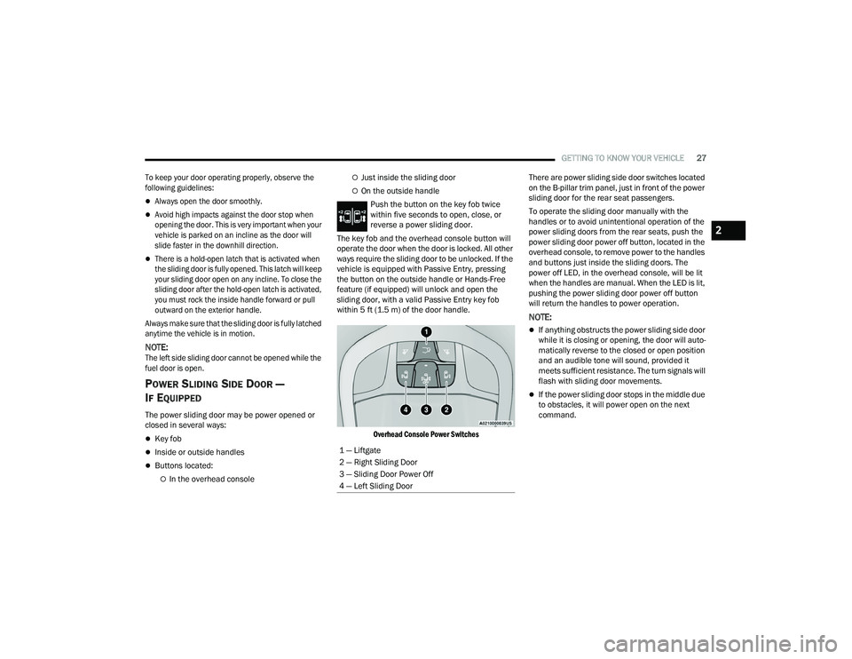
Overhead Console Power Switches
There are power sliding side door switches located
on the B-pillar trim panel, just in front of the power
sliding door for the rear seat passengers.
To operate the sliding door manually with the
handles or to avoid unintentional operation of the
power sliding doors from the rear seats, push the
power sliding door power off button, located in the
overhead console, to remove power to the handles
and buttons just inside the sliding doors. The
power off LED, in the overhead console, will be lit
when the handles are manual. When the LED is lit,
pushing the power sliding door power off button
will return the handles to power operation.
NOTE:
If anything obstructs the power sliding side door
while it is closing or opening, the door will auto
-
matically reverse to the closed or open position
and an audible tone will sound, provided it
meets sufficient resistance. The turn signals will
flash with sliding door movements.
If the power sliding door stops in the middle due
to obstacles, it will power open on the next
command.
1 — Liftgate
2 — Right Sliding Door
3 — Sliding Door Power Off
4 — Left Sliding Door
2
21_RUP_OM_EN_USC_t.book Page 27
Page 114 of 401
112GETTING TO KNOW YOUR INSTRUMENT PANEL
INSTRUMENT CLUSTER DESCRIPTIONS
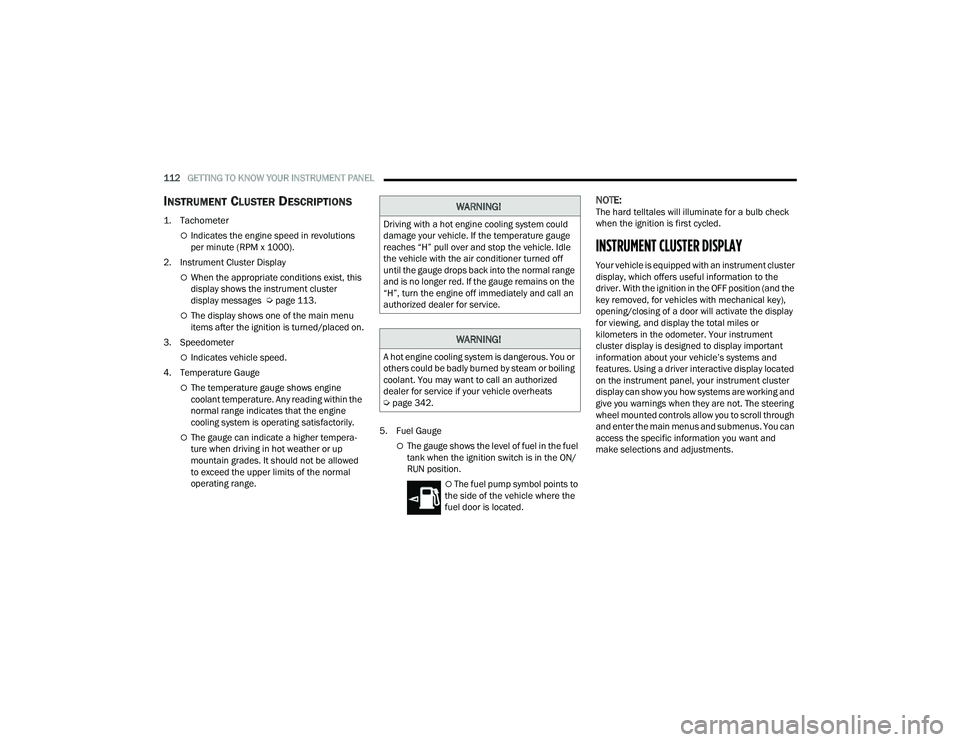
1. Tachometer
Indicates the engine speed in revolutions
per minute (RPM x 1000).
2. Instrument Cluster Display
When the appropriate conditions exist, this
display shows the instrument cluster
display messages Ú page 113.
The display shows one of the main menu
items after the ignition is turned/placed on.
3. Speedometer
Indicates vehicle speed.
4. Temperature Gauge
The temperature gauge shows engine
coolant temperature. Any reading within the
normal range indicates that the engine
cooling system is operating satisfactorily.
The gauge can indicate a higher tempera -
ture when driving in hot weather or up
mountain grades. It should not be allowed
to exceed the upper limits of the normal
operating range. 5. Fuel GaugeThe gauge shows the level of fuel in the fuel
tank when the ignition switch is in the ON/
RUN position.
The fuel pump symbol points to
the side of the vehicle where the
fuel door is located.
NOTE:The hard telltales will illuminate for a bulb check
when the ignition is first cycled.
INSTRUMENT CLUSTER DISPLAY
Your vehicle is equipped with an instrument cluster
display, which offers useful information to the
driver. With the ignition in the OFF position (and the
key removed, for vehicles with mechanical key),
opening/closing of a door will activate the display
for viewing, and display the total miles or
kilometers in the odometer. Your instrument
cluster display is designed to display important
information about your vehicle’s systems and
features. Using a driver interactive display located
on the instrument panel, your instrument cluster
display can show you how systems are working and
give you warnings when they are not. The steering
wheel mounted controls allow you to scroll through
and enter the main menus and submenus. You can
access the specific information you want and
make selections and adjustments.
WARNING!
Driving with a hot engine cooling system could
damage your vehicle. If the temperature gauge
reaches “H” pull over and stop the vehicle. Idle
the vehicle with the air conditioner turned off
until the gauge drops back into the normal range
and is no longer red. If the gauge remains on the
“H”, turn the engine off immediately and call an
authorized dealer for service.
WARNING!
A hot engine cooling system is dangerous. You or
others could be badly burned by steam or boiling
coolant. You may want to call an authorized
dealer for service if your vehicle overheats
Ú page 342.
21_RUP_OM_EN_USC_t.book Page 112
Page 115 of 401
GETTING TO KNOW YOUR INSTRUMENT PANEL113
INSTRUMENT CLUSTER DISPLAY
L
OCATION AND CONTROLS
The vehicle’s instrument cluster is equipped with
an instrument cluster display (base or premium
cluster), which offers useful information to the
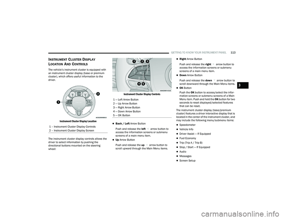
driver.
Instrument Cluster Display Location
The instrument cluster display controls allows the
driver to select information by pushing the
directional buttons mounted on the steering
wheel:
Instrument Cluster Display Controls
Back / Left
Arrow Button
Push and release the left arrow button to
access the information screens or submenu
screens of a main menu item.
Up Arrow Button
Push and release the up arrow button to
scroll upward through the Main Menu items.
Right Arrow Button
Push and release the right arrow button to
access the information screens or submenu
screens of a main menu item.
Down Arrow Button
Push and release the down arrow button to
scroll downward through the Main Menu items.
OK Button
Push the OK button to access/select the infor -
mation screens or submenu screens of a Main
Menu item. Push and hold the OK button for two
seconds to reset displayed/selected features
that can be reset.
The instrument cluster display (base/premium
cluster) features a driver interactive display that is
located in the center of the instrument cluster, and
may include the following menu/submenu items:
Speedometer
Vehicle Info
Driver Assist — If Equipped
Fuel Economy
Trip (Trip A / Trip B)
Stop / Start — If Equipped
Audio
Messages
Screen Setup
1 – Instrument Cluster Display Controls
2 – Instrument Cluster Display Screen
1 — Left Arrow Button
2 — Up Arrow Button
3 — Right Arrow Button
4 — Down Arrow Button
5 — OK Button
3
21_RUP_OM_EN_USC_t.book Page 113