roof rack CHRYSLER PACIFICA 2021 Owners Manual
[x] Cancel search | Manufacturer: CHRYSLER, Model Year: 2021, Model line: PACIFICA, Model: CHRYSLER PACIFICA 2021Pages: 401, PDF Size: 26.88 MB
Page 6 of 401
4
LIFTGATE ................................................................. 98 To Unlock/Open The Liftgate...........................98
To Lock/Close The Liftgate ..............................98
Power Liftgate — If Equipped ...........................98
Hands-Free Liftgate — If Equipped ............... 100
Cargo Area Features ..................................... 101
STOW ‘N PLACE ROOF RACK —
IF EQUIPPED ........................................................ 106
Deploying The Crossbars .............................. 107Stowing The Crossbars ................................. 108
GETTING TO KNOW YOUR
INSTRUMENT PANEL
INSTRUMENT CLUSTER....................................... 110
Instrument Cluster Descriptions .................. 112
INSTRUMENT CLUSTER DISPLAY ...................... 112
Instrument Cluster Display Location And
Controls .......................................................... 113
Oil Life Reset ................................................. 114
KeySense Cluster Messages —
If Equipped..................................................... 115
Instrument Cluster Display Menu Items ..... 116
Battery Saver On/Battery Saver Mode
Message — Electrical Load Reduction
Actions — If Equipped.................................... 121 TRIP COMPUTER ................................................ 122
WARNING LIGHTS AND MESSAGES ................. 123
Red Warning Lights ....................................... 123
Yellow Warning Lights ................................... 126Yellow Indicator Lights .................................. 129
Green Indicator Lights .................................. 129
White Indicator Lights ................................... 130Blue Indicator Lights ..................................... 130
ONBOARD DIAGNOSTIC SYSTEM — OBD II...... 130
Onboard Diagnostic System
(OBD II) Cybersecurity ................................... 130
EMISSIONS INSPECTION AND MAINTENANCE
PROGRAMS ....................................................... 131STARTING AND OPERATING
STARTING THE ENGINE ...................................... 132
Normal Starting ............................................ 132
AutoPark ........................................................ 133Cold Weather Operation
(Below –22°F Or −30°C) ............................ 135
After Starting — Warming Up The Engine..... 135
If Engine Fails To Start ................................. 135
To Turn Off The Engine Using ENGINE
START/STOP Button ...................................... 136 ENGINE BLOCK HEATER — IF EQUIPPED .......... 136
ENGINE BREAK-IN RECOMMENDATIONS ........ 136
PARKING BRAKE ................................................. 137 Electric Park Brake (EPB) ............................ 137
AUTOMATIC TRANSMISSION ............................. 139
Ignition Park Interlock................................... 140
Brake/Transmission Shift Interlock
(BTSI) System ................................................ 141
9-Speed Automatic Transmission ............... 141
Gear Ranges .................................................. 141
ALL-WHEEL DRIVE (AWD) — IF EQUIPPED ...... 144
ACTIVE NOISE CANCELLATION .......................... 144
POWER STEERING............................................... 144
STOP/START SYSTEM — IF EQUIPPED ............. 145 Autostop Mode .............................................. 145
Possible Reasons The Engine Does Not
Autostop......................................................... 145
To Start The Engine While In Autostop ........ 146To Manually Turn Off The Stop/Start
System ........................................................... 146
To Manually Turn On The Stop/Start
System ........................................................... 147
System Malfunction ...................................... 147
21_RUP_OM_EN_USC_t.book Page 4
Page 98 of 401
96GETTING TO KNOW YOUR VEHICLE
OPENING AND CLOSING THE POWER
S
UNSHADE — IF EQUIPPED
The sunshade has two programmed open
positions: half-open and full-open. When opening
the sunshade from the closed position, the
sunshade will always stop at the half-open position
regardless of express or manual open operation.
The switch must be actuated again to continue to
the full-open position.
Express Open/Close
Push the sunshade open switch and release it
within one second and the sunshade will open to
the half-open position and stop automatically.
Push and release the sunshade open switch again
from the half-open position and the sunshade will
open to the full-open position and stop
automatically. This is called Express Open.
Push the sunshade close switch and release it
within one second and the sunshade will close
automatically from any position. If the sunroof is
completely closed, the shade will close fully and
stop automatically. This is called Express Close.
NOTE:
During Express Open or Express Close opera -
tion, any movement of the sunshade switch will
stop the shade.
If the sunroof is open, the shade will close to the
half-open position. Pushing the shade close
button again will automatically close both the
sunroof and shade completely.
Manual Open/Close
Push and hold the sunshade open switch and the
shade will open to the half-open position and stop
automatically. Push and hold the sunshade open
switch again and the shade will open automatically
to the full-open position.
To close the shade, push and hold the sunshade
close switch.
Any release of the switch will stop the movement
and the sunshade will remain in a partially opened
condition until the switch is pushed again.
PINCH PROTECT FEATURE
This feature will detect an obstruction in the
closing of the sunroof during the Express Close
operation. If an obstruction in the path of the
sunroof is detected, the sunroof will automatically
retract. Remove the obstruction if this occurs.
NOTE:If three consecutive sunroof close attempts result
in Pinch Protect reversals, Pinch Protect will
disable and the sunroof must be closed in Manual
Mode.
VENTING SUNROOF
Push and release the "Vent" button within one
second and the sunroof will open to the vent
position. This is called “Express Vent”, and it will
occur regardless of sunroof position.
NOTE:If the sunshade is in the closed position when the
vent switch is pushed, the sunshade will automati -
cally cycle to the halfway open position prior to the
sunroof opening to the Vent position.
IGNITION OFF OPERATION
The power sunroof switch will remain active for up
to approximately 10 minutes after the ignition
switch is placed in the OFF position. Opening either
front door will cancel this feature.
NOTE:Ignition off time is programmable through the
Uconnect system Ú page 189.
SUNROOF MAINTENANCE
Use only a non-abrasive cleaner and a soft cloth to
clean the glass panel. Periodically check for and
clear out any debris that may have collected in the
tracks.
21_RUP_OM_EN_USC_t.book Page 96
Page 108 of 401
106GETTING TO KNOW YOUR VEHICLE
4. Remove the filter and dump the debris in a trash can. Lightly tap the filter on the collection
bin to remove loose debris from the filter. If the
filter is clogged from extended use, have the
filter replaced by an authorized dealer.
5. Reverse the procedure to reinstall.
NOTE:The debris bin must be fully installed and locked
for the vacuum to function properly.
Hose Access Port
The hose access port is located behind the access
panel behind the third row seat on the driver’s
side.
To Remove Vacuum Hose For Cleaning
1. Open the access panel.
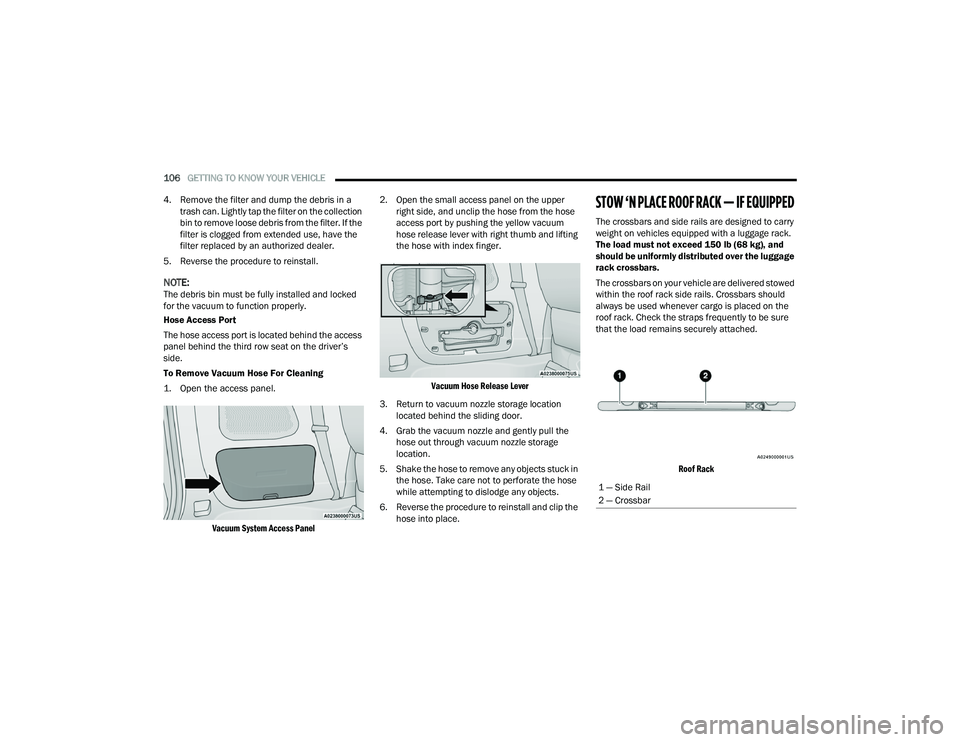
Vacuum System Access Panel
2. Open the small access panel on the upper
right side, and unclip the hose from the hose
access port by pushing the yellow vacuum
hose release lever with right thumb and lifting
the hose with index finger.
Vacuum Hose Release Lever
3. Return to vacuum nozzle storage location located behind the sliding door.
4. Grab the vacuum nozzle and gently pull the hose out through vacuum nozzle storage
location.
5. Shake the hose to remove any objects stuck in the hose. Take care not to perforate the hose
while attempting to dislodge any objects.
6. Reverse the procedure to reinstall and clip the hose into place.
STOW ‘N PLACE ROOF RACK — IF EQUIPPED
The crossbars and side rails are designed to carry
weight on vehicles equipped with a luggage rack.
The load must not exceed 150 lb (68 kg), and
should be uniformly distributed over the luggage
rack crossbars.
The crossbars on your vehicle are delivered stowed
within the roof rack side rails. Crossbars should
always be used whenever cargo is placed on the
roof rack. Check the straps frequently to be sure
that the load remains securely attached.
Roof Rack
1 — Side Rail
2 — Crossbar
21_RUP_OM_EN_USC_t.book Page 106
Page 109 of 401
GETTING TO KNOW YOUR VEHICLE107
The Stow ‘N Place roof rack does not increase the
total load carrying capacity of the vehicle. Be sure
the total load of cargo inside the vehicle plus that
on the external rack does not exceed the maximum
vehicle load capacity.
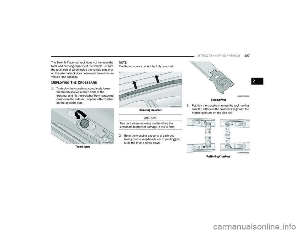
DEPLOYING THE CROSSBARS
1. To deploy the crossbars, completely loosen the thumb screws at both ends of the
crossbar and lift the crossbar from its stowed
position in the side rail. Repeat with crossbar
on the opposite side.
Thumb Screw
NOTE:The thumb screws cannot be fully removed.
Removing Crossbars
2. Bend the crossbar supports at each end, taking care to keep hand clear of pivoting joint.
Slide the thumb screw down.
Bending Pivot
3. Position the crossbars across the roof making sure the letters on the crossbars align with the
matching letters on the side rail.
Positioning Crossbars
CAUTION!
Use care when removing and handling the
crossbars to prevent damage to the vehicle.
2
21_RUP_OM_EN_USC_t.book Page 107
Page 111 of 401
GETTING TO KNOW YOUR VEHICLE109
(Continued)
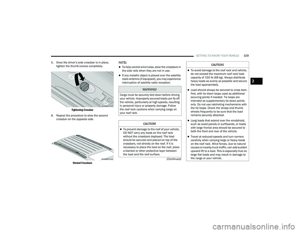
5. Once the driver’s side crossbar is in place,
tighten the thumb screws completely.
Tightening Crossbar
6. Repeat the procedure to stow the second crossbar on the opposite side.
Stowed Crossbars
NOTE:
To help control wind noise, stow the crossbars in
the side rails when they are not in use.
If any metallic object is placed over the satellite
radio antenna (if equipped), you may experience
interruption of satellite radio reception.
WARNING!
Cargo must be securely tied down before driving
your vehicle. Improperly secured loads can fly off
the vehicle, particularly at high speeds, resulting
in personal injury or property damage. Follow
the roof rack cautions when carrying cargo on
your roof rack.
CAUTION!
To prevent damage to the roof of your vehicle,
DO NOT carry any loads on the roof rack
without the crossbars deployed. The load
should be secured and placed on top of the
crossbars, not directly on the roof. If it is
necessary to place the load on the roof, place
a blanket or other protective layer between
the load and the roof surface.
To avoid damage to the roof rack and vehicle,
do not exceed the maximum roof rack load
capacity of 150 lb (68 kg). Always distribute
heavy loads as evenly as possible and secure
the load appropriately.
Load should always be secured to cross bars
first, with tie down loops used as additional
securing points if needed. Tie loops are
intended as supplementary tie down points
only. Do not use ratcheting mechanisms with
the tie loops. Check the straps and thumb
wheels frequently to be sure that the load
remains securely attached.
Long loads that extend over the windshield,
such as wood panels or surfboards, or loads
with large frontal area should be secured to
both the front and rear of the vehicle.
Travel at reduced speeds and turn corners
carefully when carrying large or heavy loads
on the roof rack. Wind forces, due to natural
causes or nearby truck traffic, can add sudden
upward lift to a load. This is especially true on
large flat loads and may result in damage to
the cargo or your vehicle.
CAUTION!
2
21_RUP_OM_EN_USC_t.book Page 109
Page 272 of 401
270SAFETY
Supplemental Side Air Bag Inflatable Curtains
(SABICs)
This vehicle is equipped with Supplemental Side
Air Bag Inflatable Curtains (SABICs).
Supplemental Side Air Bag Inflatable Curtains
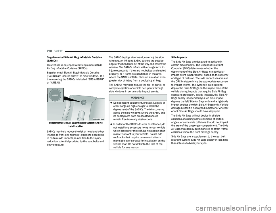
(SABICs) are located above the side windows. The
trim covering the SABICs is labeled “SRS AIRBAG”
or “AIRBAG.”
Supplemental Side Air Bag Inflatable Curtain (SABIC) Label Location
SABICs may help reduce the risk of head and other
injuries to front and rear seat outboard occupants
in certain side impacts, in addition to the injury
reduction potential provided by the seat belts and
body structure. The SABIC deploys downward, covering the side
windows. An inflating SABIC pushes the outside
edge of the headliner out of the way and covers the
window. The SABICs inflate with enough force to
injure occupants if they are not belted and seated
properly, or if items are positioned in the area
where the SABICs inflate. Children are at an even
greater risk of injury from a deploying air bag.
The SABICs may help reduce the risk of partial or
complete ejection of vehicle occupants through
side windows in certain side impact events.
Side Impacts
The Side Air Bags are designed to activate in
certain side impacts. The Occupant Restraint
Controller (ORC) determines whether the
deployment of the Side Air Bags in a particular
impact event is appropriate, based on the severity
and type of collision. The side impact sensors aid
the ORC in determining the appropriate response
to impact events. The system is calibrated to
deploy the Side Air Bags on the impact side of the
vehicle during impacts that require Side Air Bag
occupant protection. In side impacts, the Side Air
Bags deploy independently; a left side impact
deploys the left Side Air Bags only and a right-side
impact deploys the right Side Air Bags only. Vehicle
damage by itself is not a good indicator of whether
or not Side Air Bags should have deployed.
The Side Air Bags will not deploy in all side
collisions, including some collisions at certain
angles, or some side collisions that do not impact
the area of the passenger compartment. The Side
Air Bags may deploy during angled or offset frontal
collisions where the front air bags deploy.
Side Air Bags are a supplement to the seat belt
restraint system. Side Air Bags deploy in less time
than it takes to blink your eyes.
WARNING!
Do not mount equipment, or stack luggage or
other cargo up high enough to block the
deployment of the SABICs. The trim covering
above the side windows where the SABIC and
its deployment path are located should
remain free from any obstructions.
In order for the SABICs to work as intended, do
not install any accessory items in your vehicle
which could alter the roof. Do not add an after
-
market sunroof to your vehicle. Do not add
roof racks that require permanent attach -
ments (bolts or screws) for installation on the
vehicle roof. Do not drill into the roof of the
vehicle for any reason.
21_RUP_OM_EN_USC_t.book Page 270
Page 396 of 401
394 Onboard Diagnostic System
.......................... 130Operating Precautions................................... 130Operator Manual Owner's Manual........................................ 387Outside Rearview Mirrors......................... 57, 58Overheating, Engine...................................... 321
P
Paint Care...................................................... 374Parking Brake................................................ 137ParkSense Active Park Assist........................ 164ParkSense System, Rear............................... 158Passive Entry................................................... 24Pets............................................................... 292Placard, Tire And Loading Information........... 360PowerBrakes....................................................... 377Inverter........................................................ 91Mirrors......................................................... 58Outlet (Auxiliary Electrical Outlet)................ 89Seats.................................................... 47, 49Steering..................................................... 144Power SeatsDown........................................................... 47Forward....................................................... 47Rearward..................................................... 47Up................................................................ 47
Power Sliding DoorOn / Off Switch..................................... 27, 98Pregnant Women And Seat Belts.................. 258Preparation For Jacking................................ 299PretensionersSeat Belts................................................. 258
R
Radial Ply Tires............................................. 364Radiator Cap (Coolant Pressure Cap)........... 343Radio Operation............................................ 233Rear Air Conditioning................................ 74, 80Rear Camera................................................. 172Rear Cross Path............................................ 243Rear ParkSense System............................... 158Rear Seat Removal.......................................... 35Rear View......................................................... 57Reclining Front Seats....................................... 34Recreational Towing..................................... 185Reformulated Gasoline................................. 378Refrigerant.................................................... 336Release, Hood................................................. 97Reminder, Lights On........................................ 63Reminder, Seat Belt...................................... 251Remote ControlStarting System........................................... 19
Remote Keyless EntryArm The Alarm.............................................22Disarm The Alarm........................................22Programming Additional Key Fobs...............16Remote StartingExit Remote Start Mode...............................20Remote Starting System..................................19Replacement Bulbs....................................... 354Replacement Tires........................................ 366Reporting Safety Defects.............................. 386Restraints, Child............................................ 275Restraints, Head..............................................52Roof Luggage Rack....................................... 106Rotation, Tires............................................... 372
S
Safety Checks Inside Vehicle........................ 292Safety Checks Outside Vehicle...................... 293Safety Defects, Reporting............................. 386Safety Information, Tire................................. 355Safety Tips.................................................... 291Safety, Exhaust Gas...................................... 294Schedule, Maintenance................................ 327Seat Belt Reminder....................................... 125Seat Belts............................................ 251, 292Adjustable Shoulder Belt.......................... 255Adjustable Upper Shoulder Anchorage..... 255
21_RUP_OM_EN_USC_t.book Page 394