Auto stop CHRYSLER PACIFICA 2022 User Guide
[x] Cancel search | Manufacturer: CHRYSLER, Model Year: 2022, Model line: PACIFICA, Model: CHRYSLER PACIFICA 2022Pages: 384, PDF Size: 23.92 MB
Page 95 of 384
GETTING TO KNOW YOUR VEHICLE93
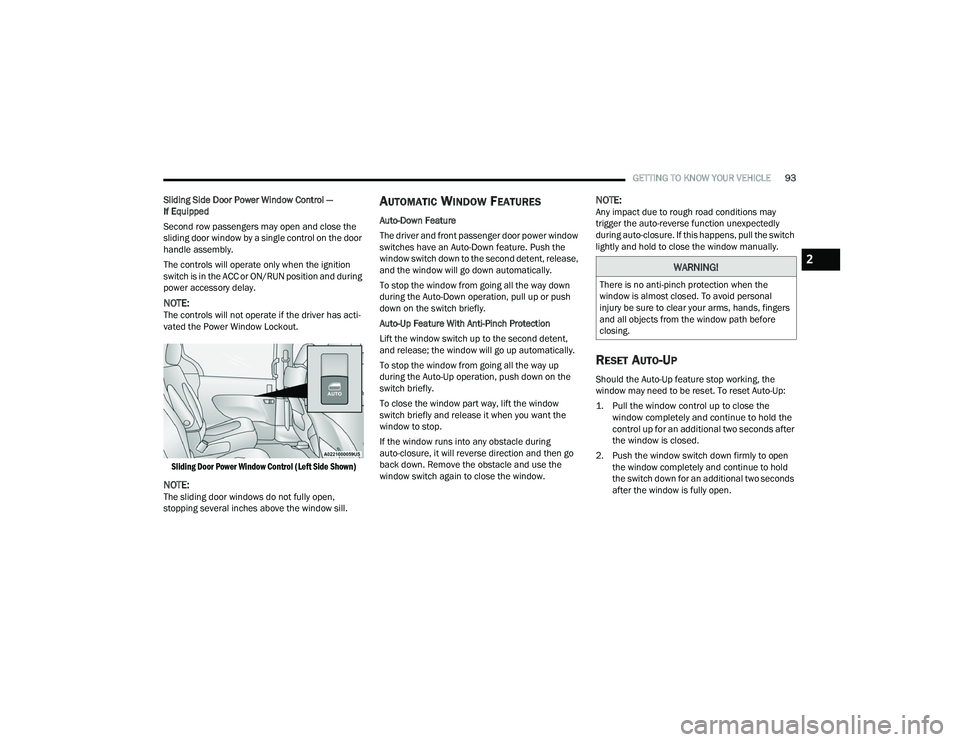
Sliding Side Door Power Window Control —
If Equipped
Second row passengers may open and close the
sliding door window by a single control on the door
handle assembly.
The controls will operate only when the ignition
switch is in the ACC or ON/RUN position and during
power accessory delay.
NOTE:The controls will not operate if the driver has acti-
vated the Power Window Lockout.
Sliding Door Power Window Control (Left Side Shown)
NOTE:The sliding door windows do not fully open,
stopping several inches above the window sill.
AUTOMATIC WINDOW FEATURES
Auto-Down Feature
The driver and front passenger door power window
switches have an Auto-Down feature. Push the
window switch down to the second detent, release,
and the window will go down automatically.
To stop the window from going all the way down
during the Auto-Down operation, pull up or push
down on the switch briefly.
Auto-Up Feature With Anti-Pinch Protection
Lift the window switch up to the second detent,
and release; the window will go up automatically.
To stop the window from going all the way up
during the Auto-Up operation, push down on the
switch briefly.
To close the window part way, lift the window
switch briefly and release it when you want the
window to stop.
If the window runs into any obstacle during
auto-closure, it will reverse direction and then go
back down. Remove the obstacle and use the
window switch again to close the window.
NOTE:Any impact due to rough road conditions may
trigger the auto-reverse function unexpectedly
during auto-closure. If this happens, pull the switch
lightly and hold to close the window manually.
RESET AUTO-UP
Should the Auto-Up feature stop working, the
window may need to be reset. To reset Auto-Up:
1. Pull the window control up to close the window completely and continue to hold the
control up for an additional two seconds after
the window is closed.
2. Push the window switch down firmly to open the window completely and continue to hold
the switch down for an additional two seconds
after the window is fully open.
WARNING!
There is no anti-pinch protection when the
window is almost closed. To avoid personal
injury be sure to clear your arms, hands, fingers
and all objects from the window path before
closing.
2
22_RUP_OM_EN_USC_t.book Page 93
Page 96 of 384
94GETTING TO KNOW YOUR VEHICLE
(Continued)
WIND BUFFETING
Wind buffeting can be described as the perception
of pressure on the ears or a helicopter-type sound
in the ears. Your vehicle may exhibit wind buffeting
with the windows down, or the sunroof (if
equipped) in certain open or partially open
positions. This is a normal occurrence and can be
minimized. If the buffeting occurs with the rear
windows open, open the front and rear windows
together to minimize the buffeting. If the buffeting
occurs with the sunroof open, adjust the sunroof
opening to minimize the buffeting or open any
window.
PANORAMIC SUNROOF — IF EQUIPPED
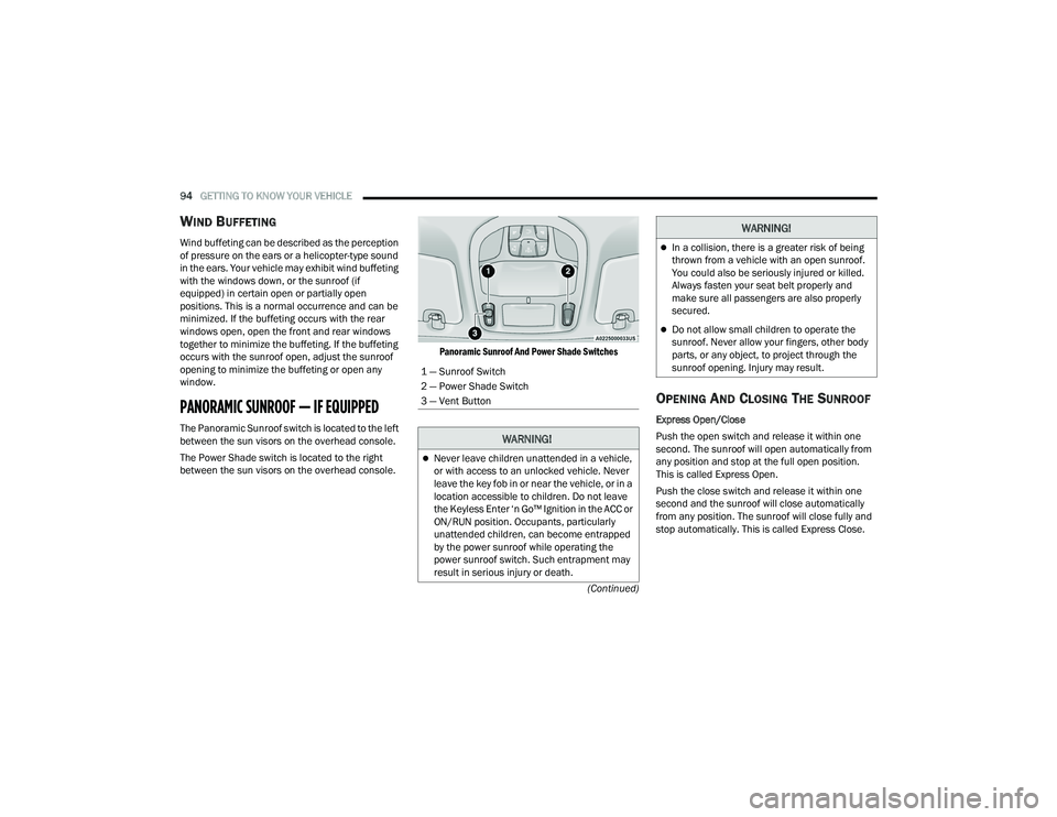
The Panoramic Sunroof switch is located to the left
between the sun visors on the overhead console.
The Power Shade switch is located to the right
between the sun visors on the overhead console.
Panoramic Sunroof And Power Shade Switches
OPENING AND CLOSING THE SUNROOF
Express Open/Close
Push the open switch and release it within one
second. The sunroof will open automatically from
any position and stop at the full open position.
This is called Express Open.
Push the close switch and release it within one
second and the sunroof will close automatically
from any position. The sunroof will close fully and
stop automatically. This is called Express Close.
1 — Sunroof Switch
2 — Power Shade Switch
3 — Vent Button
WARNING!
Never leave children unattended in a vehicle,
or with access to an unlocked vehicle. Never
leave the key fob in or near the vehicle, or in a
location accessible to children. Do not leave
the Keyless Enter ‘n Go™ Ignition in the ACC or
ON/RUN position. Occupants, particularly
unattended children, can become entrapped
by the power sunroof while operating the
power sunroof switch. Such entrapment may
result in serious injury or death.
In a collision, there is a greater risk of being
thrown from a vehicle with an open sunroof.
You could also be seriously injured or killed.
Always fasten your seat belt properly and
make sure all passengers are also properly
secured.
Do not allow small children to operate the
sunroof. Never allow your fingers, other body
parts, or any object, to project through the
sunroof opening. Injury may result.
WARNING!
22_RUP_OM_EN_USC_t.book Page 94
Page 97 of 384
GETTING TO KNOW YOUR VEHICLE95
NOTE:
During Express Open or Express Close opera -
tion, any other actuation of the switch will stop
the sunroof.
If the sunshade is in the closed position when
the open switch is pushed, the sunshade will
automatically cycle to the halfway open position
prior to the sunroof opening.
Manual Open/Close
Push and hold the open switch and the sunroof will
open to the full open position.
To close the sunroof, push and hold the close
switch.
Any release of the switch during open or close
operation will stop the movement and the sunroof
will remain in a partially open condition until the
sunroof switch is pushed again.
OPENING AND CLOSING THE POWER
S
UNSHADE — IF EQUIPPED
The sunshade has two programmed open
positions: half-open and full-open. When opening
the sunshade from the closed position, the
sunshade will always stop at the half-open position
regardless of express or manual open operation.
The switch must be actuated again to continue to
the full-open position. Express Open/Close
Push the sunshade open switch and release it
within one second and the sunshade will open to
the half-open position and stop automatically.
Push and release the sunshade open switch again
from the half-open position and the sunshade will
open to the full-open position and stop
automatically. This is called Express Open.
Push the sunshade close switch and release it
within one second and the sunshade will close
automatically from any position. If the sunroof is
completely closed, the shade will close fully and
stop automatically. This is called Express Close.
NOTE:
During Express Open or Express Close opera
-
tion, any movement of the sunshade switch will
stop the shade.
If the sunroof is open, the shade will close to the
half-open position. Pushing the shade close
button again will automatically close both the
sunroof and shade completely.
Manual Open/Close
Push and hold the sunshade open switch and the
shade will open to the half-open position and stop
automatically. Push and hold the sunshade open
switch again and the shade will open automatically
to the full-open position. To close the shade, push and hold the sunshade
close switch.
Any release of the switch will stop the movement
and the sunshade will remain in a partially opened
condition until the switch is pushed again.
PINCH PROTECT FEATURE
This feature will detect an obstruction in the
closing of the sunroof during the Express Close
operation. If an obstruction in the path of the
sunroof is detected, the sunroof will automatically
retract. Remove the obstruction if this occurs.
NOTE:
If three consecutive sunroof close attempts result in
Pinch Protect reversals, Pinch Protect will disable
and the sunroof must be closed in Manual Mode.
VENTING SUNROOF
Push and release the Vent button within one
second and the sunroof will open to the vent
position. This is called Express Vent, and it will
occur regardless of sunroof position.
NOTE:If the sunshade is in the closed position when the
vent switch is pushed, the sunshade will automati
-
cally cycle to the halfway open position prior to the
sunroof opening to the Vent position.
2
22_RUP_OM_EN_USC_t.book Page 95
Page 102 of 384
100GETTING TO KNOW YOUR VEHICLE
If the power liftgate encounters multiple
obstructions within the same cycle, the system
will automatically stop. If this occurs, the liftgate
must be operated manually.
The power liftgate will release, but not power
open, in temperatures below −12°F (−24°C).
Be sure to remove any buildup of snow or ice
from the liftgate before opening the liftgate.
If the liftgate is left open for an extended period
of time, the liftgate may need to be closed
manually to reset power liftgate functionality.
The Hands-Free Liftgate only works to open the
liftgate. Gas props support the liftgate in the open position.
However, because the gas pressure drops with
temperature, it may be necessary to assist the
props when opening the liftgate in cold weather.
NOTE:Allow the power system to open the liftgate.
Manually pushing or pulling the liftgate may
activate the liftgate obstacle detection feature and
stop the power operation or reverse its direction.
CARGO AREA FEATURES
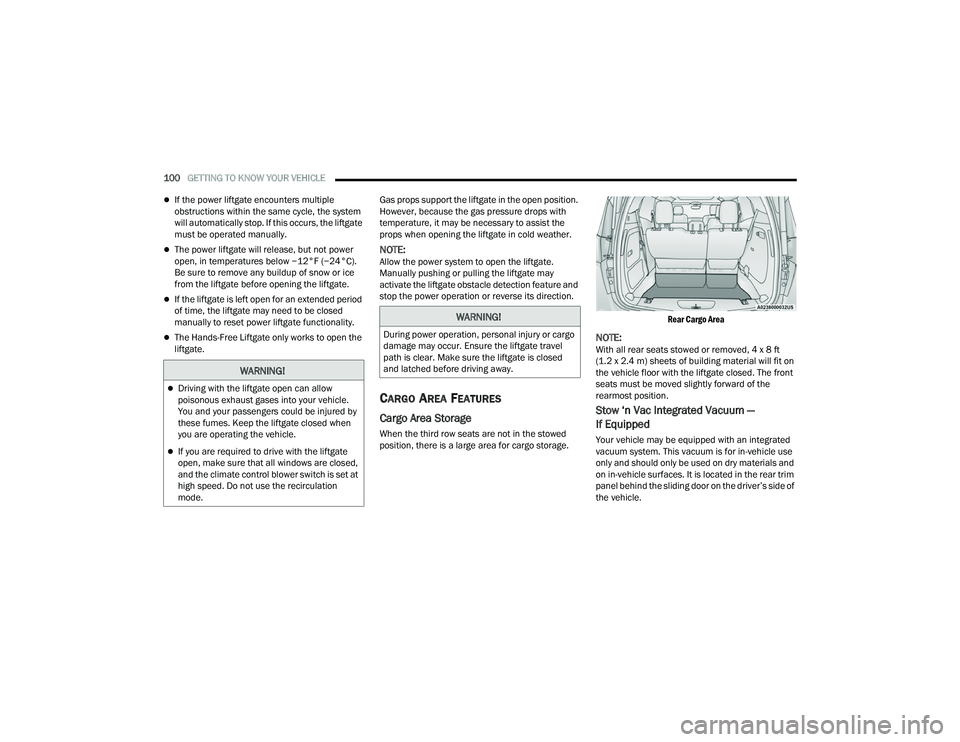
Cargo Area Storage
When the third row seats are not in the stowed
position, there is a large area for cargo storage.
Rear Cargo Area
NOTE:With all rear seats stowed or removed, 4 x 8 ft
(1.2 x 2.4 m) sheets of building material will fit on
the vehicle floor with the liftgate closed. The front
seats must be moved slightly forward of the
rearmost position.
Stow ‘n Vac Integrated Vacuum —
If Equipped
Your vehicle may be equipped with an integrated
vacuum system. This vacuum is for in-vehicle use
only and should only be used on dry materials and
on in-vehicle surfaces. It is located in the rear trim
panel behind the sliding door on the driver’s side of
the vehicle.
WARNING!
Driving with the liftgate open can allow
poisonous exhaust gases into your vehicle.
You and your passengers could be injured by
these fumes. Keep the liftgate closed when
you are operating the vehicle.
If you are required to drive with the liftgate
open, make sure that all windows are closed,
and the climate control blower switch is set at
high speed. Do not use the recirculation
mode.
WARNING!
During power operation, personal injury or cargo
damage may occur. Ensure the liftgate travel
path is clear. Make sure the liftgate is closed
and latched before driving away.
22_RUP_OM_EN_USC_t.book Page 100
Page 127 of 384
GETTING TO KNOW YOUR INSTRUMENT PANEL125
If the ABS light does not turn on when the ignition
is placed in the ON/RUN or ACC/ON/RUN position,
have the brake system inspected by an authorized
dealer.
Electronic Stability Control (ESC) Active
Warning Light — If Equipped
This warning light will indicate when the
ESC system is Active. The ESC Indicator
Light in the instrument cluster will come
on when the ignition is placed in the ON/
RUN or ACC/ON/RUN position, and when ESC is
activated. It should go out with the engine running.
If the ESC Indicator Light comes on continuously
with the engine running, a malfunction has been
detected in the ESC system. If this warning light
remains on after several ignition cycles, and the
vehicle has been driven several miles (kilometers)
at speeds greater than 30 mph (48 km/h), see an
authorized dealer as soon as possible to have the
problem diagnosed and corrected.
The ESC OFF Indicator Light and the ESC Indi -
cator Light come on momentarily each time the
ignition is placed in the ON/RUN or ACC/ON/
RUN position.
The ESC system will make buzzing or clicking
sounds when it is active. This is normal; the
sounds will stop when ESC becomes inactive.
This light will come on when the vehicle is in an
ESC event.
Electronic Stability Control (ESC) OFF
Warning Light — If Equipped
This warning light indicates the ESC is off.
Each time the ignition is turned to ON/RUN or ACC/
ON/RUN, the ESC system will be on, even if it was
turned off previously.
Service LaneSense Warning Light —
If Equipped
This warning light will illuminate when the
LaneSense system is not operating and
requires service. Please see an
authorized dealer.
LaneSense Warning Light — If Equipped
The LaneSense Warning Light will be
solid yellow when the vehicle is
approaching a lane marker. The warning
light will flash when the vehicle is
crossing the lane marker Ú page 166.
Low Fuel Warning Light
When the fuel level reaches
approximately 1.85 gal (7 L) this warning
light will turn on, and remain on until fuel
is added.
A single warning chime will sound with Low Fuel
Warning.
Low Washer Fluid Warning Light —
If Equipped
This warning light will illuminate and a
single chime will sound when the
windshield washer fluid is low.
Engine Check/Malfunction Indicator
Warning Light
The Engine Check/Malfunction Indicator
Light (MIL) is a part of an Onboard
Diagnostic System called OBD II that
monitors engine and automatic
transmission control systems. This warning light
will illuminate when the ignition is in the ON/RUN
position before engine start. If the bulb does not
come on when turning the ignition switch from OFF
to ON/RUN, have the condition checked promptly.
Certain conditions, such as a loose or missing gas
cap, poor quality fuel, etc., may illuminate the light
after engine start. The vehicle should be serviced if
the light stays on through several typical driving
styles. In most situations, the vehicle will drive
normally and will not require towing.
When the engine is running, the MIL may flash to
alert serious conditions that could lead to
immediate loss of power or severe catalytic
converter damage. The vehicle should be serviced
by an authorized dealer as soon as possible if this
occurs.3
22_RUP_OM_EN_USC_t.book Page 125
Page 130 of 384

128GETTING TO KNOW YOUR INSTRUMENT PANEL
KeySense Indicator Light —
If Equipped
The KeySense indicator is illuminated
when a KeySense key is detected upon
startup of the vehicle. The indicator will
remain lit for the entire key cycle as a
reminder that the KeySense key is in use. While
the KeySense key is in use, the vehicle will respond
to settings associated with the KeySense profile
Ú page 14.
LaneSense Indicator Light — If Equipped
The LaneSense indicator light illuminates
solid green when both lane markings
have been detected and the system is
“armed” and ready to provide visual and
torque warnings if an unintentional lane departure
occurs Ú page 166.
Parking/Headlights On Indicator Light
This indicator light will illuminate when
the parking lights or headlights are
turned on.
Stop/Start Active Indicator Light —
If Equipped
This indicator light will illuminate when
the Stop/Start function is in “Autostop”
mode Úpage 143.
Turn Signal Indicator Lights
When the left or right turn signal is
activated, the turn signal indicator will
flash independently and the
corresponding exterior turn signal lamps
will flash. Turn signals can be activated when the
multifunction lever is moved down (left) or
up (right).
NOTE:
A continuous chime will sound if the vehicle is
driven more than 1 mile (1.6 km) with either
turn signal on.
Check for an inoperative outside light bulb if
either indicator flashes at a rapid rate.
WHITE INDICATOR LIGHTS
Adaptive Cruise Control (ACC) Ready
Light — If Equipped
This indicator light will illuminate when
the vehicle equipped with ACC has been
turned on but not set Ú page 147.
Cruise Control Ready Indicator Light
This indicator light will illuminate when
the cruise control is ready, but not set
Úpage 146.
LaneSense Indicator Light — If Equipped
When the LaneSense system is ON, but
not armed, the LaneSense indicator light
illuminates solid white. This occurs when
only left, right, or neither lane line has
been detected. If a single lane line is detected, the
system is ready to provide only visual warnings if
an unintentional lane departure occurs on the
detected lane line Ú page 166.
Speed Warning Indicator Light
The white indicator will illuminate along
with a pop-up message (Speed Warning
Set to XX followed by unit), once the
feature is enabled. When the set speed is
exceeded, a continuous chime (up to 10 seconds
or until the speed is no longer exceeded) will sound
along with a Speed Warning Exceeded pop-up
message and the indicator light will turn yellow and
flash.
NOTE:The number “31” is only an example of a speed
that can be selected.
Set Speed Display
The Set Speed Display indicator light
indicates the set speed for the Cruise
Control and Adaptive Cruise Control
(ACC) settings.
22_RUP_OM_EN_USC_t.book Page 128
Page 133 of 384
131
(Continued)
STARTING AND OPERATING
STARTING THE ENGINE
Before starting your vehicle, adjust your seat,
adjust both inside and outside mirrors, and fasten
your seat belts.Start the engine with the gear selector in the
NEUTRAL (N) or PARK (P) position. Apply the brake
before shifting to any driving range.
NORMAL STARTING
To Turn On The Engine Using ENGINE START/STOP
Button
1. The transmission must be in PARK or NEUTRAL.
2. Press and hold the brake pedal while pushing the ENGINE START/STOP button once.
3. The system starts the vehicle. If the vehicle fails to start, the starter will disengage
automatically after 10 seconds.
4. If you wish to stop the cranking of the engine prior to the engine starting, push the button
again. ENGINE START/STOP Button Functions — With
Driver’s Foot Off The Brake Pedal (In PARK Or
NEUTRAL Position)
The ENGINE START/STOP button operates similar
to an ignition switch. It has three positions; OFF,
ACC, and ON/RUN. To change the ignition positions
without starting the vehicle and to use the
accessories, follow these steps:
Start with the ignition in the OFF position.
Push the ENGINE START/STOP button once to
place the ignition to the ACC position (instru
-
ment cluster will display “ACC”).
Push the ENGINE START/STOP button a second
time to place the ignition to the ON/RUN posi -
tion (instrument cluster will display “ON/RUN”).
Push the ENGINE START/STOP button a third
time to return the ignition to the OFF position
(instrument cluster will display “OFF”).
NOTE:Only press one pedal at a time while driving the
vehicle. Torque performance of the vehicle could
be reduced if both pedals are pressed at the same
time. If pressure is detected on both pedals simul -
taneously, a warning message will display in the
instrument cluster Ú page 113.
WARNING!
When exiting the vehicle, always remove the
key fob from the vehicle and lock your vehicle.
Never leave children alone in a vehicle, or with
access to an unlocked vehicle.
Allowing children to be in a vehicle unattended
is dangerous for a number of reasons. A child
or others could be seriously or fatally injured.
Children should be warned not to touch the
parking brake, brake pedal or the transmis -
sion gear selector.
Do not leave the key fob in or near the vehicle,
or in a location accessible to children, and do
not leave the ignition of a vehicle equipped
with Keyless Enter ‘n Go™ in the ACC or ON/
RUN position. A child could operate power
windows, other controls, or move the vehicle.
Do not leave children or animals inside parked
vehicles in hot weather. Interior heat buildup
may cause serious injury or death.
WARNING!
4
22_RUP_OM_EN_USC_t.book Page 131
Page 134 of 384
132STARTING AND OPERATING
AUTOPARK
AutoPark is a supplemental feature to assist with
placing the vehicle in PARK under certain
situations. It is a back-up system and should not be
relied upon as the primary method by which the
driver shifts the vehicle into PARK.
The conditions under which AutoPark will engage
are outlined on the following pages. ALWAYS DO A VISUAL CHECK
that your vehicle is in
PARK by looking for the “P” in the instrument
cluster display and on the gear selector. As an
added precaution, always apply the parking brake.
If the vehicle is not in PARK and the driver
attempts to turn off the engine, if certain
conditions are met, the vehicle will AutoPark,
automatically shifting the vehicle’s transmission to
the PARK position. The gear selector will
automatically reset itself to the PARK position. The
vehicle’s ignition will then move to the OFF position
(engine off). When AutoPark is activated the
instrument cluster will display the message
“AutoPark Engaged”.
AutoPark will engage when all of these conditions
are met:
Vehicle is equipped with a gear selector
Vehicle is not in PARK
Vehicle speed is 1.2 mph (1.9 km/h) or less
Driver has pushed the ENGINE START/STOP
button If the vehicle is not in PARK and the driver exits the
vehicle with the engine running, if certain
conditions are met, the vehicle will AutoPark,
automatically shifting the vehicle’s transmission to
the PARK position. The Electric Park Brake SAFE
HOLD feature will also activate in some conditions
Ú
page 138.
AutoPark will engage when all of these conditions
are met:
Vehicle is equipped with a gear selector
Vehicle is not in PARK
Vehicle speed is 1.2 mph (1.9 km/h) or less
Driver’s door is ajar
Driver’s seat belt is unbuckled
Brake pedal is not pressed
The message “ AutoPark Engaged ” will display in
the instrument cluster.
WARNING!
Driver inattention could lead to failure to place
the vehicle in PARK. ALWAYS DO A VISUAL
CHECK that your vehicle is in PARK by verifying
that a solid (not blinking) “P” is indicated in
the instrument cluster display and near the
gear selector. If the “P” indicator is blinking,
your vehicle is not in PARK. As an added
precaution, always apply the parking brake
when exiting the vehicle.
AutoPark is a supplemental feature. It is not
designed to replace the need to shift your
vehicle into PARK. It is a back up system and
should not be relied upon as the primary
method by which the driver shifts the vehicle
into PARK.
CAUTION!
Engine will remain running.
22_RUP_OM_EN_USC_t.book Page 132
Page 135 of 384

STARTING AND OPERATING133
(Continued)
(Continued)
AutoPark In Stop/Start Autostop Mode
AutoPark will engage when all of these condi
-
tions are met:
Vehicle is equipped with a gear selector
Vehicle is not in PARK
Vehicle speed is 1.2 mph (1.9 km/h) or less
Driver’s door is ajar
Driver’s seat belt is unbuckled or brake pedal is
not pressed
The message “ AutoPark Engaged ” will display in
the instrument cluster.
WARNING!
Never use the PARK position as a substitute
for the parking brake. Always apply the
parking brake fully when exiting the vehicle to
guard against vehicle movement and possible
injury or damage.
Your vehicle could move and injure you and
others if it is not in PARK. Check by trying to
move the transmission gear selector out of
PARK with the brake pedal released. Make
sure the transmission is in PARK before
exiting the vehicle.
The transmission may not engage PARK if the
vehicle is moving. Always bring the vehicle to a
complete stop before shifting to PARK, and
verify that the transmission gear position indi -
cator solidly indicates PARK (P) without
blinking. Ensure that the vehicle is completely
stopped, and the PARK position is properly
indicated, before exiting the vehicle.
It is dangerous to shift out of PARK or
NEUTRAL if the engine speed is higher than
idle speed. If your foot is not firmly pressing
the brake pedal, the vehicle could accelerate
quickly forward or in reverse. You could lose
control of the vehicle and hit someone or
something. Only shift into gear when the
engine is idling normally and your foot is firmly
pressing the brake pedal.
WARNING!
Unintended movement of a vehicle could
injure those in or near the vehicle. As with all
vehicles, you should never exit a vehicle while
the engine is running. Before exiting a vehicle,
always come to a complete stop, then apply
the parking brake, shift the transmission into
PARK, and turn the ignition OFF. When the
ignition is in the OFF position, the transmis -
sion is locked in PARK, securing the vehicle
against unwanted movement.
When exiting the vehicle, always make sure
the ignition is in the OFF position, remove the
key fob from the vehicle, and lock the vehicle.
Never leave children alone in a vehicle, or
with access to an unlocked vehicle. Allowing
children to be in a vehicle unattended is
dangerous for a number of reasons. A child or
others could be seriously or fatally injured.
Children should be warned not to touch the
parking brake, brake pedal or the transmis -
sion gear selector.
Do not leave the key fob in or near the vehicle
(or in a location accessible to children), and do
not leave the ignition in the ACC or ON/RUN
position. A child could operate power
windows, other controls, or move the vehicle.
WARNING!
4
22_RUP_OM_EN_USC_t.book Page 133
Page 136 of 384
134STARTING AND OPERATING
To Turn On The Engine Using ENGINE START/STOP
Button
1. The transmission must be in PARK or NEUTRAL.
2. Press and hold the brake pedal while pushing the ENGINE START/STOP button once.
To release the parking brake manually, the ignition
switch must be in the ON/RUN position. Press on
the brake pedal, then push the parking brake
switch momentarily. If the driver shifts into PARK while moving, the
vehicle may Park.
PARK will engage
ONLY when vehicle speed is
1.2 mph (1.9 km/h) or less.
The message “ Vehicle Speed is Too High to Shift
to P ” will display in the instrument cluster display if
vehicle speed is above 1.2 mph (1.9 km/h). The
gear position indicator will blink continuously until
the gear selector is returned to the proper position,
or the requested shift can be completed.
COLD WEATHER OPERATION
(B
ELOW –22°F OR −30°C)
To ensure reliable starting at these temperatures,
use of an externally powered electric engine block
heater (available from an authorized dealer) is
recommended.
AFTER STARTING — WARMING UP THE
E
NGINE
The idle speed is controlled automatically and it
will decrease as the engine warms up.
IF ENGINE FAILS TO START
CAUTION!
Damage to the transmission may occur if the
following precautions are not observed:
Shift into or out of PARK or REVERSE only after
the vehicle has come to a complete stop.
Do not shift between PARK, REVERSE,
NEUTRAL, or DRIVE when the engine is above
idle speed.
Before shifting into any gear, make sure your
foot is firmly pressing the brake pedal.WARNING!
If vehicle speed is not below 1.2 mph (1.9 km/h)
when the driver shifts into PARK, the
transmission will default to NEUTRAL until the
vehicle speed drops below 1.2 mph (1.9 km/h)
and the above conditions are met, enabling
AutoPark. A vehicle left in the NEUTRAL position
can roll. As an added precaution, always apply
the parking brake when exiting the vehicle.
WARNING!
Never pour fuel or other flammable liquid into
the throttle body air inlet opening in an
attempt to start the vehicle. This could result
in flash fire causing serious personal injury.
Do not attempt to push or tow your vehicle to
get it started. Vehicles equipped with an auto -
matic transmission cannot be started this
way. Unburned fuel could enter the catalytic
converter and once the engine has started,
ignite and damage the converter and vehicle.
If the vehicle has a discharged battery,
booster cables may be used to obtain a start
from a booster battery or the battery in
another vehicle. This type of start can be
dangerous if done improperly Ú page 300.
22_RUP_OM_EN_USC_t.book Page 134