Start CHRYSLER PACIFICA 2022 Owner's Manual
[x] Cancel search | Manufacturer: CHRYSLER, Model Year: 2022, Model line: PACIFICA, Model: CHRYSLER PACIFICA 2022Pages: 384, PDF Size: 23.92 MB
Page 45 of 384
GETTING TO KNOW YOUR VEHICLE43
Using the Auto Advance ‘n Return Feature
NOTE:
The button is only functional when the power
sliding door is open and the vehicle is in PARK.
If the door is not open or the vehicle is not in
PARK when the button is pushed, the front seat
will not move and a message will be displayed in
the instrument cluster display.
If the power sliding door is closing when the
button is pushed, the front seat will not move
and a message will be displayed in the instru -
ment cluster display.
The Auto Advance ‘n Return feature will not
function if the front doors are open.
1. Push and release the Auto Advance ‘n Return button.
2. Perform the second row Stow ‘n Go seat movement Ú page 43.
3. Push and release the Auto Advance ‘n Return button a second time. The front seat cushion
and seatback will return to the original starting
location.
NOTE:
To abort seat operation while seat is in motion,
push the Auto Advance ‘n Return button, or
push the front power seat button to stop the seat movement. Pushing the Auto Advance ‘n
Return button again will return the front seat to
the original starting location.
The Auto Advance ‘n Return system includes
obstacle detection. When the system detects an
obstacle, the seat will stop, reverse direction,
and return to the previous location. A message
will be displayed in the instrument cluster indi
-
cating that an obstacle has been detected.
If the front seat is already in a location that will
allow space for Stow ‘n Go of the second row
seat, the front seat will not move and a message
will be displayed in the instrument cluster.
If calibration of the front seat is lost, the seat will
automatically recalibrate when the Auto
Advance ‘n Return button is pushed. This may
result in the seat cushion moving forward and
downward, before moving to the location that
will allow space for the second row Stow ‘n Go
seat movement.
SECOND ROW STOW 'N GO
For Manual Seats: To stow the seat in the floor, move
the front seat all the way forward using the manual
seat adjustment bar. Move the seatback all the way
forward using the recliner handle located on the
outboard side of the cushion. Move the seat height to
at least mid position using the height adjuster handle
in the outboard side of the cushion.
For Power Seats:
Push the Auto Advance ‘n Return
button located on the B-pillar trim (if equipped)
Ú page 42.
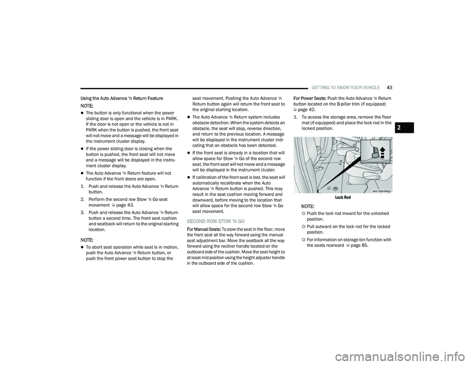
1. To access the storage area, remove the floor mat (if equipped) and place the lock rod in the
locked position.
Lock Rod
NOTE:
Push the lock rod inward for the unlocked
position.
Pull outward on the lock rod for the locked
position.
For information on storage bin function with
the seats rearward Ú page 85.
2
22_RUP_OM_EN_USC_t.book Page 43
Page 53 of 384
GETTING TO KNOW YOUR VEHICLE51
4. The third row power seat system includes obstacle detection. When the system detects
an obstacle, the motors will stop and reverse
direction. Should this occur, remove the
obstacle before pushing the button again.
HEATED SEATS
Front Heated Seats — If Equipped
The front heated seats control buttons
are located in the touchscreen.
You can choose from HI, LO or off heat settings.
The indicator lights in each switch indicate the
level of heat in use. Two indicator lights will
illuminate for HI, one for LO and none for off.
Press the heated seat button once to turn the
HI setting on.
Press the heated seat button a second time to
turn the LO setting on.
Press the heated seat button a third time to turn
the heating elements off.
The level of heat selected will stay on until the
operator changes it.
NOTE:
Once a heat setting is selected, heat will be felt
within two to five minutes.
The engine must be running for the heated
seats to operate. For information on use with the Remote Start
system, see Ú
page 21.
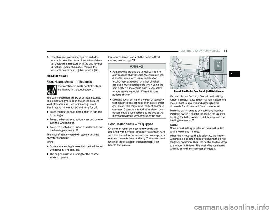
Rear Heated Seats — If Equipped
On some models, the second row seats are
equipped with heaters. There are two heated seat
switches that allow the second row passengers to
operate the seats independently. The heated seat
switches are located on the sliding side door
handle trim panels.
Second Row Heated Seat Switch (Left Side Shown)
You can choose from HI, LO or off heat settings.
Amber indicator lights in each switch indicate the
level of heat in use. Two indicator lights will
illuminate for HI, one for LO and none for off.
Push the switch once to select HI-level heating.
Push the switch a second time to select LO-level
heating. Push the switch a third time to shut the
heating elements off.
NOTE:Once a heat setting is selected, heat will be felt
within two to five minutes.
When the HI-level setting is selected, the heater
will provide a boosted heat level during the initial
stages of operation. Then, the heat output will drop
to the normal HI-level. The level of heat selected
will stay on until the operator changes it.
WARNING!
Persons who are unable to feel pain to the
skin because of advanced age, chronic illness,
diabetes, spinal cord injury, medication,
alcohol use, exhaustion or other physical
condition must exercise care when using the
seat heater. It may cause burns even at low
temperatures, especially if used for long
periods of time.
Do not place anything on the seat or seatback
that insulates against heat, such as a blanket
or cushion. This may cause the seat heater to
overheat. Sitting in a seat that has been over -
heated could cause serious burns due to the
increased surface temperature of the seat.
2
22_RUP_OM_EN_USC_t.book Page 51
Page 54 of 384
52GETTING TO KNOW YOUR VEHICLE
VENTILATED SEATS — IF EQUIPPED
Located in the first row seat cushions are
small fans that draw the air from the
passenger compartment and move air
through fine perforations in the seat
cover to help keep the driver and front passenger
cooler in higher ambient temperatures.
The fans operate at two speeds, HI and LO.
The front ventilated seats control buttons are
located in the touchscreen.
Press the ventilated seat button once to
choose HI.
Press the ventilated seat button a second time
to choose LO.
Press the ventilated seat button a third time to
turn the ventilated seat off.
NOTE:The engine must be running for the ventilated
seats to operate.
For information on use with the Remote Start
system, see Ú page 21.
ADJUSTABLE ARMREST
(F
RONT SEATS) — IF EQUIPPED
Your vehicle may be equipped with adjustable
armrests on the front seats. The armrest can be
adjusted up or down.
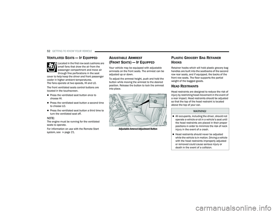
To adjust the armrest height, push and hold the
button while moving the armrest to the desired
position. Release the button to lock the armrest
into place.
Adjustable Armrest Adjustment Button
PLASTIC GROCERY BAG RETAINER
H
OOKS
Retainer hooks which will hold plastic grocery bag
handles are built into the seatbacks of the second
row rear seats, and if equipped, the backs of the
front row seats. The floor supports the partial
weight of the bagged goods.
HEAD RESTRAINTS
Head restraints are designed to reduce the risk of
injury by restricting head movement in the event of
a rear impact. Head restraints should be adjusted
so that the top of the head restraint is located
above the top of your ear.
WARNING!
All occupants, including the driver, should not
operate a vehicle or sit in a vehicle’s seat until
the head restraints are placed in their proper
positions in order to minimize the risk of neck
injury in the event of a crash.
Head restraints should never be adjusted
while the vehicle is in motion. Driving a vehicle
with the head restraints improperly adjusted
or removed could cause serious injury or
death in the event of a collision.
22_RUP_OM_EN_USC_t.book Page 52
Page 58 of 384
56GETTING TO KNOW YOUR VEHICLE
UCONNECT VOICE RECOGNITION —
IF EQUIPPED
INTRODUCING VOICE RECOGNITION
Start using Uconnect Voice Recognition (VR) with
these helpful quick tips. It provides the key Voice
Commands and tips you need to know to control
your system.
BASIC VOICE COMMANDS
The following basic Voice Commands can be given
at any point while using your Uconnect system.
Push the VR button on the steering wheel.
After the beep, say:
“Cancel ” to stop a current voice session.
“Help ” to hear a list of suggested Voice
Commands.
“ Repeat ” to listen to the system prompts again.
Notice the visual cues that inform you of your
Voice Recognition system’s status.
GET STARTED
The VR button is used to activate/deactivate
your Voice Recognition system.
Helpful hints for using Voice Recognition:
Reduce background noise. Wind noise and
passenger conversations are examples of noise
that may impact recognition.
Speak clearly at a normal pace and volume
while facing straight ahead.
Each time you give a Voice Command, first push
the VR button, wait until after the beep, then say
your Voice Command. You can also say the
vehicle “Wake Up” word and state your
command.
NOTE:The factory default Wake Up word is set to
“Hey Uconnect” and can be reprogrammed
through the Uconnect Settings. After the beep, say:
A passenger can press the VR button shortcut
on the radio status bar to also issue a
command.
You can interrupt the help message or system
prompts by pushing the VR button and saying a
Voice Command or saying the vehicle’s “Wake
Up” word and saying a command from the
current category.
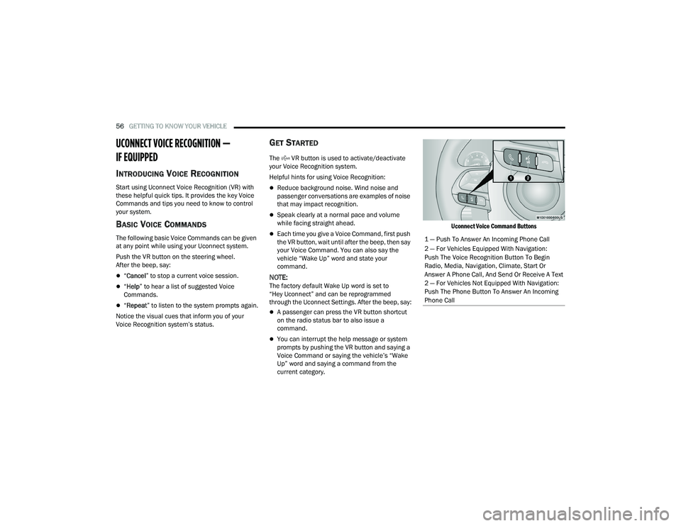
Uconnect Voice Command Buttons
1 — Push To Answer An Incoming Phone Call
2 — For Vehicles Equipped With Navigation:
Push The Voice Recognition Button To Begin
Radio, Media, Navigation, Climate, Start Or
Answer A Phone Call, And Send Or Receive A Text
2 — For Vehicles Not Equipped With Navigation:
Push The Phone Button To Answer An Incoming
Phone Call
22_RUP_OM_EN_USC_t.book Page 56
Page 65 of 384
GETTING TO KNOW YOUR VEHICLE63
2. Push the programmed HomeLink® button to confirm that the garage door opener motor
operates. If the garage door opener motor
does not operate, repeat the steps from the
beginning.
PROGRAMMING HOMELINK® TO A
M
ISCELLANEOUS DEVICE
The procedure on how to program HomeLink® to a
miscellaneous device follows the same procedure
as programming to a garage door opener
Ú page 62. Be sure to determine if the device has
a rolling code, or non-rolling code before beginning
the programming process.
NOTE:Canadian Radio Frequency (RF) laws require trans -
mitter signals to time-out (or quit) after several
seconds of transmission, which may not be long
enough for HomeLink® to pick up the signal during
programming. Similar to this Canadian law, some
U.S. gate operators are designed to time-out in the
same manner. The procedure may need to be
performed multiple times to successfully pair the
device to your HomeLink® buttons.
REPROGRAMMING A SINGLE
H
OMELINK® BUTTON
To reprogram a single HomeLink® button that has
been previously trained, without erasing all the
channels, proceed as follows. Be sure to
determine whether the new device you want to
program the HomeLink® button to has a rolling
code, or non-rolling code.
1. Place the ignition in the ON/RUN position,
without starting the engine.
2. Push and hold the desired HomeLink® button until the HomeLink® indicator light begins to
flash after 20 seconds. Do not release the
button.
3. Without releasing the button , proceed with
Step 2 in “Programming HomeLink® To A
Garage Door Opener” and follow all remaining
steps.
CANADIAN/GATE OPERATOR
P
ROGRAMMING
For programming transmitters in Canada/United
States that require the transmitter signals to
“time-out” after several seconds of transmission:
Canadian Radio Frequency (RF) laws require
transmitter signals to time-out (or quit) after
several seconds of transmission, which may not be
long enough for HomeLink® to pick up the signal
during programming. Similar to this Canadian law,
some U.S. gate operators are designed to time-out
in the same manner.
It may be helpful to unplug the device during the
cycling process to prevent possible overheating of
the garage door or gate motor.
1. Place the ignition in the ON/RUN position.
NOTE:For vehicles equipped with Keyless Enter ‘n Go™,
place the ignition in the RUN position. Make sure
while programming HomeLink® with the engine on
that your vehicle is outside of your garage, or that
the garage door remains open at all times.
2. Place the hand-held transmitter 1 to 3 inches
(3 to 8 cm) away from the HomeLink® button
you wish to program while keeping the
HomeLink® indicator light in view.
WARNING!
Your motorized door or gate will open and
close while you are programming the universal
transmitter. Do not program the transmitter if
people or pets are in the path of the door or
gate.
Do not run your vehicle in a closed garage or
confined area while programming the trans -
mitter. Exhaust gas from your vehicle contains
Carbon Monoxide (CO) which is odorless and
colorless. Carbon Monoxide is poisonous
when inhaled and can cause you and others to
be severely injured or killed.
2
22_RUP_OM_EN_USC_t.book Page 63
Page 68 of 384
66GETTING TO KNOW YOUR VEHICLE
From the O (off) position, rotate the headlight switch
clockwise to the first detent for parking light and
instrument panel light operation. Rotate the
headlight switch to the second detent for headlight,
parking light and instrument panel operation.
NOTE:For vehicles sold in Canada, rotate the headlight
switch clockwise from the parking light and
instrument panel light position to the first detent to
turn on the headlights also. Rotate to the second
detent, AUTO position, to turn on automatic head -
lights, parking lights, and instrument panel lights.
DAYTIME RUNNING LIGHTS (DRLS) —
I
F EQUIPPED
The headlights or LED light bars on your vehicle will
illuminate when the engine is started. This
provides a constant lights on condition until the
ignition is placed in the OFF position. If the parking
brake is applied, the Daytime Running Lights
(DRLs) will turn off.
NOTE:
For vehicles sold in Canada, the Daytime
Running Lights will automatically deactivate
when the front fog lights are turned on.
If allowed by law in the country in which the
vehicle was purchased, the Daytime Running
Lights can be turned on and off using the Ucon -
nect system Ú page 188.
On some vehicles, the Daytime Running Lights
may deactivate, or reduce intensity, on one side
of the vehicle (when a turn signal is activated on
that side), or on both sides of the vehicle (when
the hazard warning lights are activated).
HIGH/LOW BEAM SWITCH
Push the multifunction lever toward the instrument
panel to switch the headlights to high beams.
Pulling the multifunction lever back will turn the
low beams on.
AUTOMATIC HIGH BEAM — IF EQUIPPED
The Automatic High Beam system provides
increased forward lighting at night by automatically
controlling the high beams through the use of a
camera mounted on the windshield. This camera
detects vehicle specific light and automatically
switches from high beams to low beams until the
approaching vehicle is out of view.
NOTE:Broken, muddy, or obstructed headlights and tail -
lights of vehicles in the field of view will cause
headlights to remain on longer (closer to the
vehicle). Also, dirt, film and other obstructions on
the windshield or camera lens will cause the
system to function improperly.
To Activate
1. Select “Auto Dim High Beams” through the Uconnect system to enable the feature
Ú
page 188.
2. Rotate the headlight switch clockwise to the AUTO position.
3. Push the multifunction lever away from you to switch the headlights to the high beam
position. Refer to “Multifunction Lever” in this
section for further information.
NOTE:This system will not activate until the vehicle is at,
or above 16 mph (25 km/h).
To Deactivate
Perform either of the following steps to deactivate
the Automatic High Beam system.
1. Deselect “Auto Dim High Beams” through the Uconnect system
Ú
page 188.
2. Pull the multifunction lever toward you to switch the headlights from the high beam to
the low beam position.
3. Rotate the headlight switch counterclockwise from the AUTO to the on position.
NOTE:Once active, the Automatic High Beam system will
stop functioning below 12 mph (20 km/h).
22_RUP_OM_EN_USC_t.book Page 66
Page 73 of 384
GETTING TO KNOW YOUR VEHICLE71
Mist
Push the lever upward to the MIST position and
release for a single wiping cycle.
NOTE:The Mist feature does not activate the washer
pump; therefore, no washer fluid will be sprayed on
the windshield. The wash function must be used in
order to spray the windshield with washer fluid.
For information on wiper care and replacement,
see Ú page 320.
RAIN SENSING WIPERS — IF EQUIPPED
This feature senses rain or snowfall on the
windshield and automatically activates the wipers.
Rotate the end of the windshield wiper lever to one
of the four detent positions to activate this feature.
The sensitivity of the system is adjustable from the
windshield wiper lever. Wiper sensitivity position 1
is the least sensitive, and wiper sensitivity position
4 is the most sensitive.
NOTE:
The Rain Sensing feature will not operate when
the wiper switch is in the low or high position.
The Rain Sensing feature may not function prop -
erly when ice or dried saltwater is present on the
windshield.
Use of Rain-X or products containing wax or sili-
cone may reduce rain sensor performance.
The Rain Sensing feature can be turned on and
off through the Uconnect system Ú page 188.
The Rain Sensing system has protective features
for the wiper blades and arms. It will not operate
under the following conditions:
Low Temperature Wipe Inhibit — The Rain
Sensing feature will not operate when the igni -
tion is first placed in the ON position, when the
vehicle is stationary and the outside tempera -
ture is below 32°F (0°C), unless the wiper
control on the windshield wiper lever is moved,
the vehicle speed becomes greater than 3 mph
(5 km/h) or the outside temperature rises
above freezing.
Neutral Wipe Inhibit — The Rain Sensing feature
will not operate when the ignition is ON, when
the transmission gear selector is in the
NEUTRAL position and the vehicle speed is less
than 3 mph (5 km/h), unless the wiper control
on the windshield wiper lever is moved, the
vehicle speed is greater than 3 mph (5 km/h) or the gear selector is moved out of the NEUTRAL
position.
Remote Start Mode Inhibit — On vehicles
equipped with the Remote Start system, Rain
Sensing wipers are not operational when the
vehicle is in the Remote Start mode. Once the
operator is in the vehicle and has placed the
ignition switch in the ON/RUN position, rain
sensing wiper operation can resume, if it has
been selected, and no other inhibit conditions
(mentioned previously) exist.
REAR WIPER AND WASHER
The rear wiper/washer is operated by rotating a
switch, located at the middle of the lever.
Rotate the center portion of the lever
upward to the first detent for intermittent
operation and to the second detent for
continuous rear wiper operation.
Rear Window Washer Operation Pushing the windshield wiper lever
forward activates the rear window
washer. If the lever is pushed while on
the intermittent setting, the wipers will
turn on and operate for several wipe cycles after
the lever is released, and then resume the
intermittent interval previously selected. If the
lever is pushed while the wipers are in the off
position, the wipers will operate several wipe
cycles, then turn off.
2
22_RUP_OM_EN_USC_t.book Page 71
Page 84 of 384
82GETTING TO KNOW YOUR VEHICLE
REAR BLOWER CONTROL
The rear blower control can be manually
set to off, or any fixed blower speed by
pushing the blower control buttons. This
allows the rear seat occupants to control
the volume of air circulated in the rear of the
vehicle. The larger of the two icons increases
blower speed, whereas the smaller of the two icons
decreases the blower speed.
REAR MODE CONTROL
Push this button on the Rear Climate
Controls to change the air distribution
mode for the rear passengers.
PANEL MODE
Air comes from the outlets in the
headliner. Each of these outlets can be
individually adjusted to direct the flow of
air. Moving the air vanes of the outlets to
one side will shut off the airflow.
BI-LEVEL MODE
Air comes from both the headliner outlets
and the floor outlets.
NOTE:In many temperature positions, the Bi-Level mode
is designed to provide cooler air out of the head -
liner outlets and warmer air from the floor outlets.
FLOOR MODE
Air comes from the floor outlets.
REAR CLIMATE CONTROL/BLOWER OFF
To manually set the rear blower controls
to off, press the Rear Climate Control/
Blower Off button.
AUTOMATIC TEMPERATURE CONTROL
(ATC) — I
F EQUIPPED
Automatic Operation
1. Push the AUTO button on the faceplate, or the
AUTO button on the touchscreen on the
Automatic Temperature Control (ATC) Panel.
2. Next, adjust the temperature you would like the system to maintain by adjusting the driver
and passenger temperature control buttons.
Once the desired temperature is displayed, the
system will achieve and automatically
maintain that comfort level. 3. When the system is set up for your comfort
level, it is not necessary to change the
settings. You will experience the greatest
efficiency by simply allowing the system to
function automatically.
NOTE:
It is not necessary to move the temperature
settings for cold or hot vehicles. The system
automatically adjusts the temperature, mode,
and blower speed to provide comfort as quickly
as possible.
The temperature can be displayed in U.S. or
Metric units by selecting the U.S./Metric
customer-programmable feature within the
Uconnect system Ú page 188.
To provide you with maximum comfort in the
Automatic mode during cold start-ups, the blower
fan will remain on low until the engine warms up.
The blower will increase in speed and transition
into Auto mode.
Manual Operation Override
This system offers a full complement of manual
override features. The AUTO symbol in the front
Automatic Temperature Control (ATC) display will
be turned off when the system is being used in the
manual mode.
22_RUP_OM_EN_USC_t.book Page 82
Page 85 of 384
GETTING TO KNOW YOUR VEHICLE83
CLIMATE VOICE COMMANDS
Adjust vehicle temperatures hands-free and keep
everyone comfortable while you keep moving
ahead. (If vehicle is equipped with climate control.)
Push the VR button on the steering wheel. After the
beep, say one of the following commands:
“Set driver temperature to 70 degrees ”
“Set passenger temperature to 70 degrees ”
Did you know : Voice Command for Climate may only
be used to adjust the interior temperature of your
vehicle. Voice Command will not work to adjust the
heated seats or steering wheel if equipped.
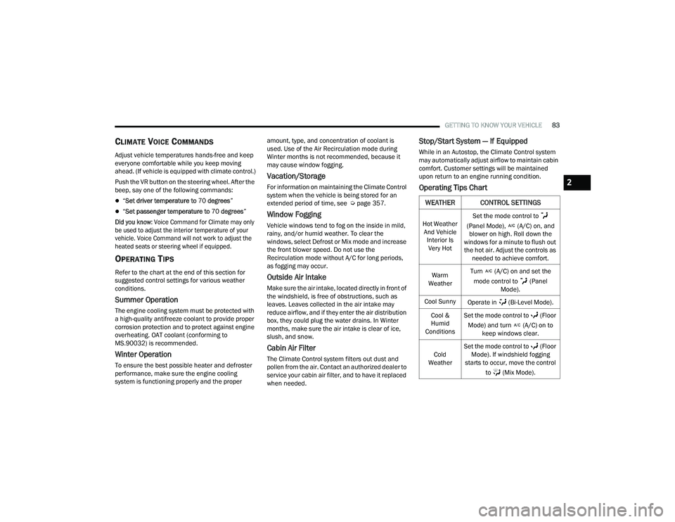
OPERATING TIPS
Refer to the chart at the end of this section for
suggested control settings for various weather
conditions.
Summer Operation
The engine cooling system must be protected with
a high-quality antifreeze coolant to provide proper
corrosion protection and to protect against engine
overheating. OAT coolant (conforming to
MS.90032) is recommended.
Winter Operation
To ensure the best possible heater and defroster
performance, make sure the engine cooling
system is functioning properly and the proper amount, type, and concentration of coolant is
used. Use of the Air Recirculation mode during
Winter months is not recommended, because it
may cause window fogging.
Vacation/Storage
For information on maintaining the Climate Control
system when the vehicle is being stored for an
extended period of time, see Ú
page 357.
Window Fogging
Vehicle windows tend to fog on the inside in mild,
rainy, and/or humid weather. To clear the
windows, select Defrost or Mix mode and increase
the front blower speed. Do not use the
Recirculation mode without A/C for long periods,
as fogging may occur.
Outside Air Intake
Make sure the air intake, located directly in front of
the windshield, is free of obstructions, such as
leaves. Leaves collected in the air intake may
reduce airflow, and if they enter the air distribution
box, they could plug the water drains. In Winter
months, make sure the air intake is clear of ice,
slush, and snow.
Cabin Air Filter
The Climate Control system filters out dust and
pollen from the air. Contact an authorized dealer to
service your cabin air filter, and to have it replaced
when needed.
Stop/Start System — If Equipped
While in an Autostop, the Climate Control system
may automatically adjust airflow to maintain cabin
comfort. Customer settings will be maintained
upon return to an engine running condition.
Operating Tips Chart
WEATHER CONTROL SETTINGS
Hot Weather
And Vehicle Interior Is Very Hot Set the mode control to
(Panel Mode), (A/C) on, and blower on high. Roll down the
windows for a minute to flush out the hot air. Adjust the controls as needed to achieve comfort.
Warm
Weather Turn (A/C) on and set the
mode control to (Panel Mode).
Cool Sunny Operate in (Bi-Level Mode).
Cool &
Humid
Conditions Set the mode control to (Floor
Mode) and turn (A/C) on to keep windows clear.
Cold
Weather Set the mode control to (Floor
Mode). If windshield fogging
starts to occur, move the control
to (Mix Mode).
2
22_RUP_OM_EN_USC_t.book Page 83
Page 92 of 384
90GETTING TO KNOW YOUR VEHICLE
(Continued)
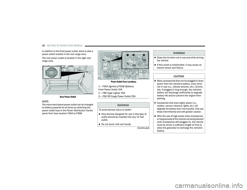
In addition to the front power outlet, there is also a
power outlet located in the rear cargo area.
The rear power outlet is located in the right rear
cargo area.
Rear Power Outlet
NOTE:The instrument panel power outlet can be changed
to battery powered at all times by switching the
power outlet fuse in the Power Distribution Center
panel from fuse location F95A to F95B.
Power Outlet Fuse Locations
1 — F95A (Ignition)/F95B (Battery)
Front Power Outlet 10A
2 — F85 Cigar Lighter 20A
3 — F60 RR Cargo Power Outlet 20A
WARNING!
To avoid serious injury or death:
Only devices designed for use in this type of
outlet should be inserted into any 12 Volt
outlet.
Do not touch with wet hands.
Close the lid when not in use and while driving
the vehicle.
If this outlet is mishandled, it may cause an
electric shock and failure.
CAUTION!
Many accessories that can be plugged in draw
power from the vehicle's battery, even when
not in use (i.e., cellular phones, etc.). Eventu
-
ally, if plugged in long enough, the vehicle's
battery will discharge sufficiently to degrade
battery life and/or prevent the engine from
starting.
Accessories that draw higher power (i.e.,
coolers, vacuum cleaners, lights, etc.) will
degrade the battery even more quickly. Only use
these intermittently and with greater caution.
After the use of high power draw accessories,
or long periods of the vehicle not being started
(with accessories still plugged in), the vehicle
must be driven a sufficient length of time to
allow the generator to recharge the vehicle's
battery.
WARNING!
22_RUP_OM_EN_USC_t.book Page 90