display CHRYSLER PACIFICA 2022 Owner's Manual
[x] Cancel search | Manufacturer: CHRYSLER, Model Year: 2022, Model line: PACIFICA, Model: CHRYSLER PACIFICA 2022Pages: 384, PDF Size: 23.92 MB
Page 84 of 384
82GETTING TO KNOW YOUR VEHICLE
REAR BLOWER CONTROL
The rear blower control can be manually
set to off, or any fixed blower speed by
pushing the blower control buttons. This
allows the rear seat occupants to control
the volume of air circulated in the rear of the
vehicle. The larger of the two icons increases
blower speed, whereas the smaller of the two icons
decreases the blower speed.
REAR MODE CONTROL
Push this button on the Rear Climate
Controls to change the air distribution
mode for the rear passengers.
PANEL MODE
Air comes from the outlets in the
headliner. Each of these outlets can be
individually adjusted to direct the flow of
air. Moving the air vanes of the outlets to
one side will shut off the airflow.
BI-LEVEL MODE
Air comes from both the headliner outlets
and the floor outlets.
NOTE:In many temperature positions, the Bi-Level mode
is designed to provide cooler air out of the head -
liner outlets and warmer air from the floor outlets.
FLOOR MODE
Air comes from the floor outlets.
REAR CLIMATE CONTROL/BLOWER OFF
To manually set the rear blower controls
to off, press the Rear Climate Control/
Blower Off button.
AUTOMATIC TEMPERATURE CONTROL
(ATC) — I
F EQUIPPED
Automatic Operation
1. Push the AUTO button on the faceplate, or the
AUTO button on the touchscreen on the
Automatic Temperature Control (ATC) Panel.
2. Next, adjust the temperature you would like the system to maintain by adjusting the driver
and passenger temperature control buttons.
Once the desired temperature is displayed, the
system will achieve and automatically
maintain that comfort level. 3. When the system is set up for your comfort
level, it is not necessary to change the
settings. You will experience the greatest
efficiency by simply allowing the system to
function automatically.
NOTE:
It is not necessary to move the temperature
settings for cold or hot vehicles. The system
automatically adjusts the temperature, mode,
and blower speed to provide comfort as quickly
as possible.
The temperature can be displayed in U.S. or
Metric units by selecting the U.S./Metric
customer-programmable feature within the
Uconnect system Ú page 188.
To provide you with maximum comfort in the
Automatic mode during cold start-ups, the blower
fan will remain on low until the engine warms up.
The blower will increase in speed and transition
into Auto mode.
Manual Operation Override
This system offers a full complement of manual
override features. The AUTO symbol in the front
Automatic Temperature Control (ATC) display will
be turned off when the system is being used in the
manual mode.
22_RUP_OM_EN_USC_t.book Page 82
Page 91 of 384
GETTING TO KNOW YOUR VEHICLE89
Plugging in a phone or another USB device may
cause the connection to a previous device to be
lost.
NOTE:Charge unsupported devices with the Charge Only
USB ports. If an unsupported device is plugged into
a Media USB port, a message will display on the
touchscreen that the device is not supported by
the system.
POWER OUTLETS
Your vehicle is equipped with 12 Volt (15 Amp)
power outlets, and 5 Volt (2.5 Amp) USB ports, that
can be used to power cellular phones, small
electronics and other low powered electrical
accessories. The power outlets can be labeled with
either a “key” or a “battery” symbol to indicate how
the outlet is powered. Power outlets labeled with a
key symbol are powered when the ignition is in the
ACC or ON/RUN position, while the outlets labeled
with a battery symbol are connected directly to the
battery and powered at all times.
NOTE:All accessories connected to the battery powered
outlets should be removed or turned off when the
vehicle is not in use to protect the battery against
discharge. Depending on the type of center console your
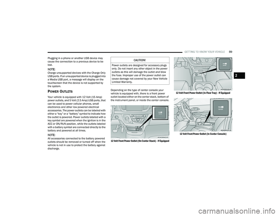
vehicle is equipped with, there is a front power
outlet located either on the center stack, bottom of
the instrument panel, or inside the center console.
12 Volt Front Power Outlet (On Center Stack) - If Equipped
12 Volt Front Power Outlet (In Floor Tray) - If Equipped
12 Volt Front Power Outlet (In Center Console)
CAUTION!
Power outlets are designed for accessory plugs
only. Do not insert any other object in the power
outlets as this will damage the outlet and blow
the fuse. Improper use of the power outlet can
cause damage not covered by your New Vehicle
Limited Warranty.
2
22_RUP_OM_EN_USC_t.book Page 89
Page 114 of 384
112GETTING TO KNOW YOUR INSTRUMENT PANEL
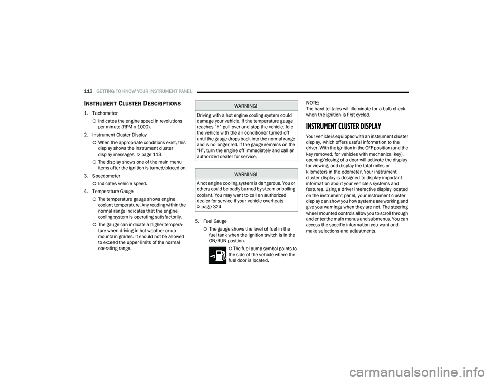
INSTRUMENT CLUSTER DESCRIPTIONS
1. Tachometer
Indicates the engine speed in revolutions
per minute (RPM x 1000).
2. Instrument Cluster Display
When the appropriate conditions exist, this
display shows the instrument cluster
display messages Ú page 113.
The display shows one of the main menu
items after the ignition is turned/placed on.
3. Speedometer
Indicates vehicle speed.
4. Temperature Gauge
The temperature gauge shows engine
coolant temperature. Any reading within the
normal range indicates that the engine
cooling system is operating satisfactorily.
The gauge can indicate a higher tempera -
ture when driving in hot weather or up
mountain grades. It should not be allowed
to exceed the upper limits of the normal
operating range. 5. Fuel GaugeThe gauge shows the level of fuel in the
fuel tank when the ignition switch is in the
ON/RUN position.
The fuel pump symbol points to
the side of the vehicle where the
fuel door is located.
NOTE:The hard telltales will illuminate for a bulb check
when the ignition is first cycled.
INSTRUMENT CLUSTER DISPLAY
Your vehicle is equipped with an instrument cluster
display, which offers useful information to the
driver. With the ignition in the OFF position (and the
key removed, for vehicles with mechanical key),
opening/closing of a door will activate the display
for viewing, and display the total miles or
kilometers in the odometer. Your instrument
cluster display is designed to display important
information about your vehicle’s systems and
features. Using a driver interactive display located
on the instrument panel, your instrument cluster
display can show you how systems are working and
give you warnings when they are not. The steering
wheel mounted controls allow you to scroll through
and enter the main menus and submenus. You can
access the specific information you want and
make selections and adjustments.
WARNING!
Driving with a hot engine cooling system could
damage your vehicle. If the temperature gauge
reaches “H” pull over and stop the vehicle. Idle
the vehicle with the air conditioner turned off
until the gauge drops back into the normal range
and is no longer red. If the gauge remains on the
“H”, turn the engine off immediately and call an
authorized dealer for service.
WARNING!
A hot engine cooling system is dangerous. You or
others could be badly burned by steam or boiling
coolant. You may want to call an authorized
dealer for service if your vehicle overheats
Ú page 324.
22_RUP_OM_EN_USC_t.book Page 112
Page 115 of 384
GETTING TO KNOW YOUR INSTRUMENT PANEL113
INSTRUMENT CLUSTER DISPLAY
L
OCATION AND CONTROLS
The vehicle’s instrument cluster is equipped with
an instrument cluster display (base or premium
cluster), which offers useful information to the
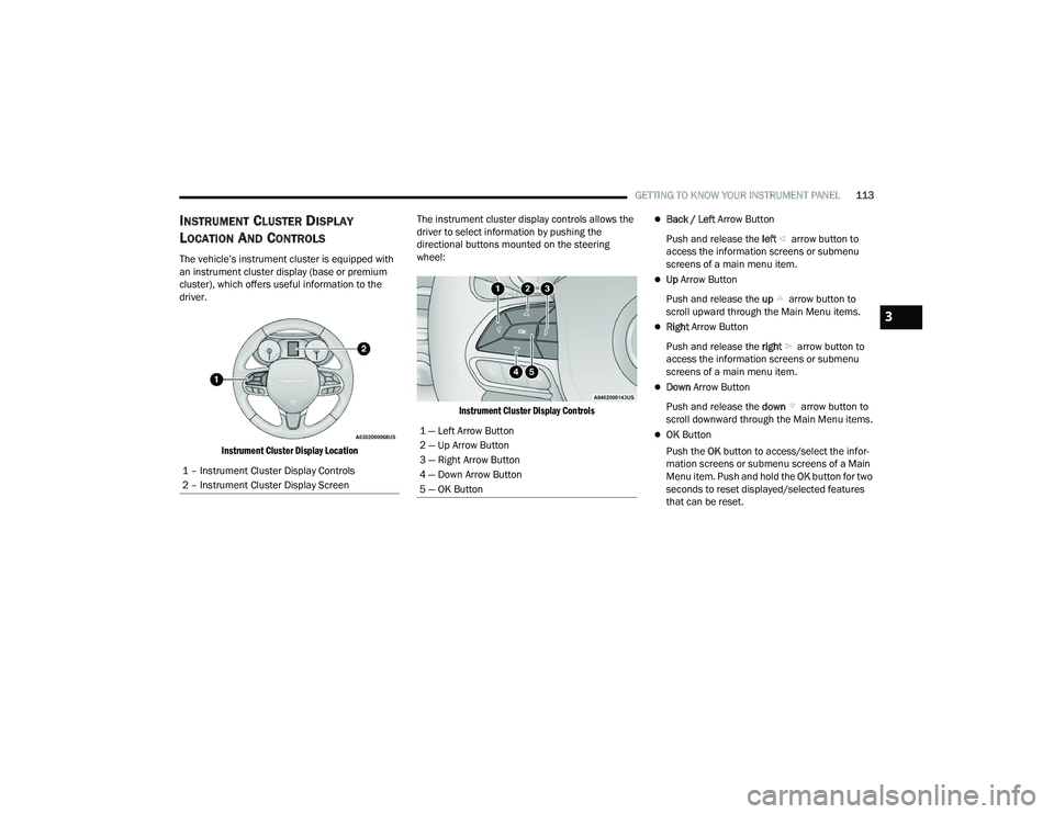
driver.
Instrument Cluster Display Location
The instrument cluster display controls allows the
driver to select information by pushing the
directional buttons mounted on the steering
wheel:
Instrument Cluster Display Controls
Back / Left Arrow Button
Push and release the left arrow button to
access the information screens or submenu
screens of a main menu item.
Up Arrow Button
Push and release the up arrow button to
scroll upward through the Main Menu items.
Right Arrow Button
Push and release the right arrow button to
access the information screens or submenu
screens of a main menu item.
Down Arrow Button
Push and release the down arrow button to
scroll downward through the Main Menu items.
OK Button
Push the OK button to access/select the infor -
mation screens or submenu screens of a Main
Menu item. Push and hold the OK button for two
seconds to reset displayed/selected features
that can be reset.
1 – Instrument Cluster Display Controls
2 – Instrument Cluster Display Screen1 — Left Arrow Button
2 — Up Arrow Button
3 — Right Arrow Button
4 — Down Arrow Button
5 — OK Button
3
22_RUP_OM_EN_USC_t.book Page 113
Page 116 of 384
114GETTING TO KNOW YOUR INSTRUMENT PANEL
ENGINE OIL LIFE
Your vehicle is equipped with an engine oil
change indicator system. The “Oil Change
Required” message will display for approxi-
mately five seconds after a single chime has
sounded, to indicate it is time to change the
engine oil. The engine oil change indicator
system is duty cycle based, which means the
engine oil change interval may fluctuate, depen -
dent upon your personal driving style.
Unless reset, this message will continue to
display each time the ignition is cycled to the
ON/RUN position.
To reset the oil change indicator after
performing the scheduled maintenance, refer to
the following procedure.
NOTE:This procedure should only be performed after
scheduled maintenance is completed. Resetting
oil life other than when associated with a
scheduled maintenance may result in damage due
to not properly maintaining the engine oil. Oil Life Reset
1. Without pressing the brake pedal, push the
ENGINE START/STOP button and place the
ignition in the ON/RUN position (do not start
the vehicle.)
2. Push the OK button to enter the instrument
cluster display menu screen.
3. Push and release the down arrow button to
access the ”Vehicle Info” menu screen.
4. Push the left arrow button or right arrow
button to access the “Oil Life” submenu.
5. Hold the OK button to reset the “Oil Life” to
100%.
6. Push the up arrow button to exit the
instrument cluster display menu screen. Secondary Method For Oil Life Reset Procedure
1. Without pushing the brake pedal, place the
ignition in the ON/RUN position (do not start
the engine).
2. Fully press the accelerator pedal, slowly, three times within 10 seconds.
3. Without pushing the brake pedal, place the ignition in the OFF position.
NOTE:If the indicator message illuminates when you start
the vehicle, the oil change indicator system did not
reset. If necessary, repeat this procedure.
22_RUP_OM_EN_USC_t.book Page 114
Page 117 of 384
GETTING TO KNOW YOUR INSTRUMENT PANEL115
KEYSENSE CLUSTER MESSAGES — IF EQUIPPED
When the KeySense key is in use there will be:
Continuous, dedicated telltale
Unique Display Splash Screen
With KeySense in use there will be multiple associated messages shown in the following table:
Setting Instrument Cluster Display Message
None – With vehicle ignition ON “KeySense in use. Max vehicle speed set to xx MPH/or km/h”
Max Vehicle Speed
“Max speed reached. KeySense in use” supported by a chime
“Approaching max speed xx MPH/km/h” supported by a chime
Start Up Fuel Alert message “Range to empty xxx miles or km”
Early Low Fuel Alert Message “Fuel Low”
ParkSense “Feature cannot be disabled. KeySense in use”
Blind Spot “Feature cannot be disabled. KeySense in use”
Forward Collision Warning “Feature cannot be disabled. KeySense in use”
3
22_RUP_OM_EN_USC_t.book Page 115
Page 118 of 384
116GETTING TO KNOW YOUR INSTRUMENT PANEL
INSTRUMENT CLUSTER DISPLAY MENU
I
TEMS
The instrument cluster display can be used to view
the main menu items for several features. Use the
up and down arrow buttons to scroll through
the driver interactive display menu options until
the desired menu is reached Ú page 113.
NOTE:The instrument cluster display menu items display
in the center of the instrument cluster. Menu items
may vary depending on your vehicle features.
Speedometer
Push and release the up or down arrow
button until Speedometer is highlighted in the
instrument cluster display. Push and release the
OK button to toggle between MPH and km/h.
Vehicle Info
Push and release the up or down arrow
button until Vehicle Info is highlighted in the
instrument cluster display. Push the left or
right arrow button to scroll through the following
information submenus: Tire Pressure
If tire pressure is
OK for all tires, a vehicle ICON is
displayed with tire pressure values in each corner
of the ICON.
If one or more tires have low pressure, “Inflate Tire
To XX” is displayed with the vehicle ICON, and the
tire pressure values in each corner of the ICON with
the pressure value of the low tire displayed in a
different color than the other tire pressure value.
If the Tire Pressure system requires service,
“Service Tire Pressure System” is displayed.
Tire PSI is an information only function and cannot
be reset Ú page 236.
Coolant Temp
Displays the actual coolant temperature.
Transmission Temp
Displays the actual transmission temperature.
Oil Temp — If Equipped
Displays the actual oil temperature.
Oil Pressure
Displays the actual oil pressure. Oil Life
Displays the remaining engine oil life as a
percentage.
To reset the Oil Life, you must hold the
OK button.
The “Hold OK to Reset” instruction will be
displayed at all times, but the following conditions
will need to be met in order to reset Oil Life:
The ignition must be in the ON/RUN position.
If the conditions are met, holding the OK button will
reset the gauge and the numeric display will return
to 100%.
If the conditions are not met, a pop-up message
will display for five seconds, describing the
required conditions, and then the Oil Life screen
will reappear.
Battery Voltage
Displays the actual battery voltage.
Engine Hours — If Equipped
Displays the number of hours of engine operation.
22_RUP_OM_EN_USC_t.book Page 116
Page 119 of 384
GETTING TO KNOW YOUR INSTRUMENT PANEL117
Driver Assist — If Equipped
Push and release the up or down arrow
button until the Driver Assist display icon is
highlighted in the instrument cluster display.
Fuel Economy
Push and release the up or down arrow
button until the Fuel Economy Menu item is
highlighted in the instrument cluster display.
The Fuel Economy Menu will display the following:
Two submenu pages that can be toggled
between using the left and right arrow
buttons; one with Current Value displayed and
one without the Current Value displayed:
Average Fuel Economy (MPG, L/100 km, or
km/L)
Range To Empty (miles or km)
Current Fuel Economy (MPG, L/100 km, or
km/L)
The Max and Min values will correspond to
the particular engine requirements
Hold OK to reset average fuel economy informa -
tion.
Trip Info
Push and release the up or down arrow
button until the Trip Menu item is highlighted in the
instrument cluster display. Push the left or
right arrow button to scroll through the Trip A
and Trip B submenus. The Trip information will
display the following:
Distance
Average Fuel Economy
Elapsed Time
Hold the OK button to reset feature information.
Stop / Start – If Equipped
Push and release the up or down arrow
button until the Stop/Start menu title is displayed
in the instrument cluster display.
Audio
Push and release the up or down arrow
button until the Audio Menu displays in the
instrument cluster display.
Messages
Push and release the up or down arrow
button until Messages is highlighted in the
instrument cluster display. This feature shows the
number of stored warning messages. Pushing the
right arrow button will allow you to see what the
stored messages are.
NOTE:The pop-up messages indicate the status of the
system and/or the conditions that need to be met.
Messages remain in the stored stack until
condition is cleared.
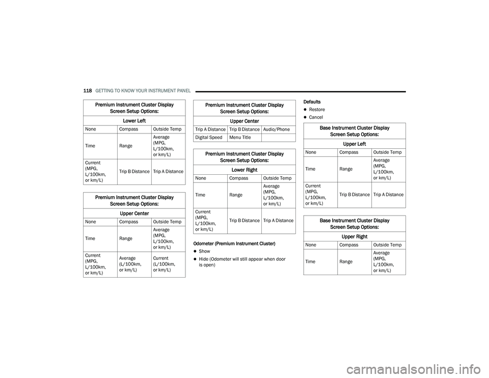
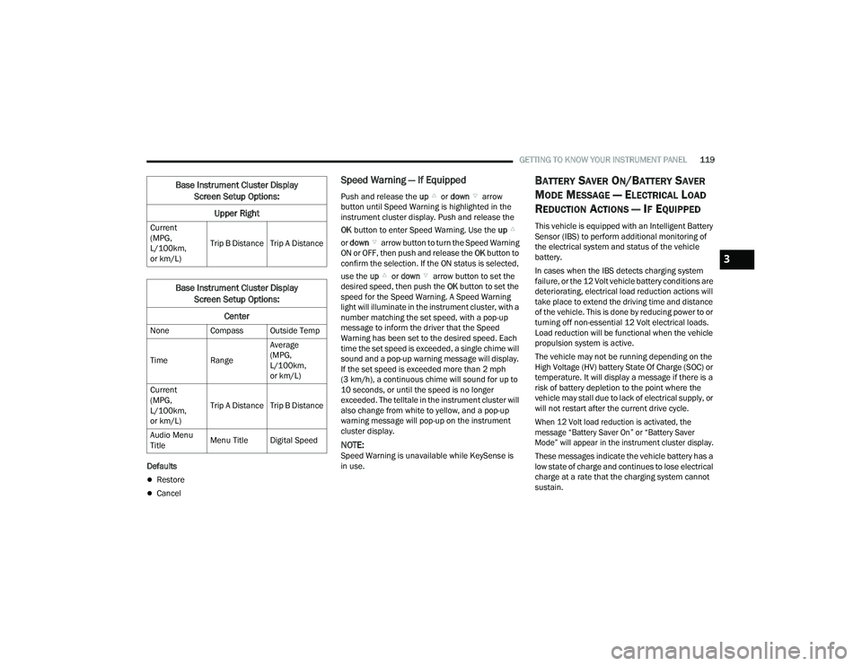
Screen Setup
Push and release the up or down arrow
button until the Screen Setup Menu displays in the
instrument cluster display. Push and release the
OK button to enter the submenus. The Screen
Setup feature allows you to change what
information is displayed in the instrument cluster
as well as the location that information is
displayed.
3
22_RUP_OM_EN_USC_t.book Page 117
Page 120 of 384
118GETTING TO KNOW YOUR INSTRUMENT PANEL
Odometer (Premium Instrument Cluster)
Show
Hide (Odometer will still appear when door
is open) Defaults
Restore
Cancel
Premium Instrument Cluster Display
Screen Setup Options:
Lower Left
None Compass Outside Temp
Time Range Average
(MPG,
L/100km,
or km/L)
Current
(MPG,
L/100km,
or km/L) Trip B Distance Trip A Distance
Premium Instrument Cluster Display
Screen Setup Options:
Upper Center
None Compass Outside Temp
Time Range Average
(MPG,
L/100km,
or km/L)
Current
(MPG,
L/100km,
or km/L) Average
(L/100km,
or km/L)
Current
(L/100km,
or km/L)
Trip A Distance Trip B Distance Audio/Phone
Digital Speed Menu Title
Premium Instrument Cluster Display
Screen Setup Options:
Lower Right
None Compass Outside Temp
Time Range Average
(MPG,
L/100km,
or km/L)
Current
(MPG,
L/100km,
or km/L) Trip B Distance Trip A Distance
Premium Instrument Cluster Display
Screen Setup Options:
Upper Center
Base Instrument Cluster Display Screen Setup Options:
Upper Left
None Compass Outside Temp
Time Range Average
(MPG,
L/100km,
or km/L)
Current
(MPG,
L/100km,
or km/L) Trip B Distance Trip A Distance
Base Instrument Cluster Display
Screen Setup Options:
Upper Right
None Compass Outside Temp
Time Range Average
(MPG,
L/100km,
or km/L)
22_RUP_OM_EN_USC_t.book Page 118
Page 121 of 384
GETTING TO KNOW YOUR INSTRUMENT PANEL119
Defaults
Restore
Cancel
Speed Warning — If Equipped
Push and release the up or down arrow
button until Speed Warning is highlighted in the
instrument cluster display. Push and release the
OK button to enter Speed Warning. Use the up
or down arrow button to turn the Speed Warning
ON or OFF, then push and release the OK button to
confirm the selection. If the ON status is selected,
use the up or down arrow button to set the
desired speed, then push the OK button to set the
speed for the Speed Warning. A Speed Warning
light will illuminate in the instrument cluster, with a
number matching the set speed, with a pop-up
message to inform the driver that the Speed
Warning has been set to the desired speed. Each
time the set speed is exceeded, a single chime will
sound and a pop-up warning message will display.
If the set speed is exceeded more than 2 mph
(3 km/h), a continuous chime will sound for up to
10 seconds, or until the speed is no longer
exceeded. The telltale in the instrument cluster will
also change from white to yellow, and a pop-up
warning message will pop-up on the instrument
cluster display.
NOTE:Speed Warning is unavailable while KeySense is
in use.
BATTERY SAVER ON/BATTERY SAVER
M
ODE MESSAGE — ELECTRICAL LOAD
R
EDUCTION ACTIONS — IF EQUIPPED
This vehicle is equipped with an Intelligent Battery
Sensor (IBS) to perform additional monitoring of
the electrical system and status of the vehicle
battery.
In cases when the IBS detects charging system
failure, or the 12 Volt vehicle battery conditions are
deteriorating, electrical load reduction actions will
take place to extend the driving time and distance
of the vehicle. This is done by reducing power to or
turning off non-essential 12 Volt electrical loads.
Load reduction will be functional when the vehicle
propulsion system is active.
The vehicle may not be running depending on the
High Voltage (HV) battery State Of Charge (SOC) or
temperature. It will display a message if there is a
risk of battery depletion to the point where the
vehicle may stall due to lack of electrical supply, or
will not restart after the current drive cycle.
When 12 Volt load reduction is activated, the
message “Battery Saver On” or “Battery Saver
Mode” will appear in the instrument cluster display.
These messages indicate the vehicle battery has a
low state of charge and continues to lose electrical
charge at a rate that the charging system cannot
sustain.
Current
(MPG,
L/100km,
or km/L)
Trip B Distance Trip A Distance
Base Instrument Cluster Display
Screen Setup Options:
Center
None Compass Outside Temp
Time Range Average
(MPG,
L/100km,
or km/L)
Current
(MPG,
L/100km,
or km/L) Trip A Distance Trip B Distance
Audio Menu
Title Menu Title Digital Speed
Base Instrument Cluster Display
Screen Setup Options:
Upper Right
3
22_RUP_OM_EN_USC_t.book Page 119