Maintenance CHRYSLER PACIFICA 2022 Owners Manual
[x] Cancel search | Manufacturer: CHRYSLER, Model Year: 2022, Model line: PACIFICA, Model: CHRYSLER PACIFICA 2022Pages: 384, PDF Size: 23.92 MB
Page 3 of 384
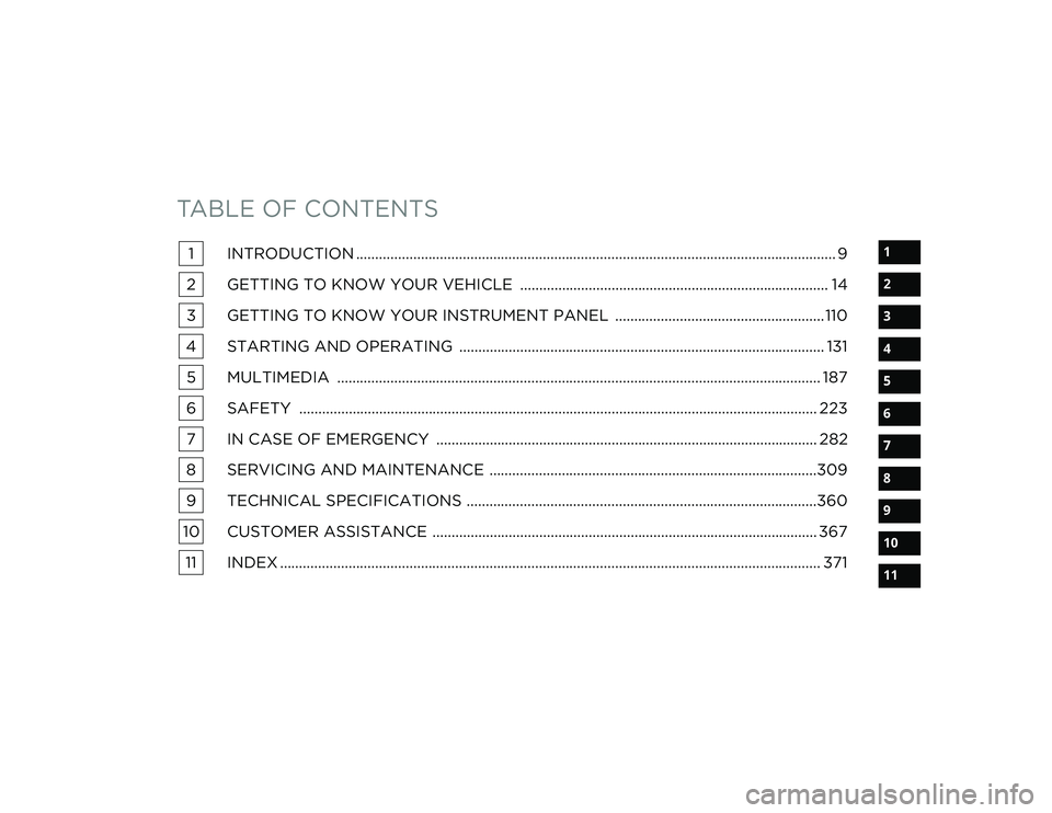
TABLE OF CONTENTS
1
2
3
4
5
6
7
8
9
10
11
1 INTRODUCTION .............................................................................................................................. 9
2 GETTING TO KNOW YOUR VEHICLE ................................................................................. 14
3 GETTING TO KNOW YOUR INSTRUMENT PANEL ....................................................... 110
4 STARTING AND OPERATING ................................................................................................ 131 5 MULTIMEDIA ............................................................................................................................... 187
6 SAFETY ........................................................................................................................................ 223 7 IN CASE OF EMERGENCY .................................................................................................... 282
8 SERVICING AND MAINTENANCE ......................................................................................309
9 TECHNICAL SPECIFICATIONS ............................................................................................360
10 CUSTOMER ASSISTANCE ..................................................................................................... 367 11 INDEX .............................................................................................................................................. 371
22_RUP_OM_EN_USC_t.book Page 1
Page 5 of 384
3
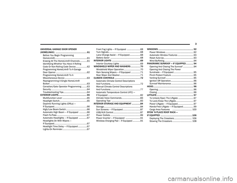
UNIVERSAL GARAGE DOOR OPENER
(HOMELINK®) ....................................................... 61 Before You Begin Programming
HomeLink®.......................................................61
Erasing All The HomeLink® Channels ............61
Identifying Whether You Have A Rolling
Code Or Non-Rolling Code Device ...................62
Programming HomeLink® To A Garage
Door Opener .....................................................62
Programming HomeLink® To A
Miscellaneous Device ......................................63
Reprogramming A Single HomeLink®
Button ...............................................................63
Canadian/Gate Operator Programming .........63
Security .............................................................64
Troubleshooting Tips ........................................64
EXTERIOR LIGHTS.................................................. 65
Multifunction Lever ..........................................65
Headlight Switch...............................................65
Daytime Running Lights (DRLs) —
If Equipped........................................................66
High/Low Beam Switch....................................66
Automatic High Beam — If Equipped .............66
Flash-To-Pass ...................................................67
Automatic Headlights — If Equipped ..............67
Headlights On With Wipers —
If Equipped........................................................67
Headlight Time Delay — If Equipped ...............67
Lights-On Reminder..........................................67 Front Fog Lights — If Equipped .......................68
Turn Signals ......................................................68
Lane Change Assist — If Equipped ..................68
Battery Saver ...................................................68
INTERIOR LIGHTS ..................................................69
Interior Courtesy Lights ...................................69
WINDSHIELD WIPER AND WASHERS .................70
Windshield Wiper Operation ............................70
Rain Sensing Wipers — If Equipped ................71
Rear Wiper And Washer...................................71
CLIMATE CONTROLS .............................................72
Automatic Climate Control Descriptions
And Functions ...................................................72
Manual Climate Control Descriptions
And Functions ...................................................77
Automatic Temperature Control (ATC) —
If Equipped .......................................................82
Climate Voice Commands................................83
Operating Tips .................................................83
INTERIOR STORAGE AND EQUIPMENT ............... 84
Storage..............................................................84
Sun Screens — If Equipped..............................87
USB/AUX Control ..............................................87
Power Outlets ...................................................89
Power Inverter — If Equipped .........................91
Wireless Charging Pad — If Equipped .............91 WINDOWS .............................................................. 92
Power Windows ................................................ 92
Automatic Window Features ........................... 93
Reset Auto-Up................................................... 93
Wind Buffeting.................................................. 94
PANORAMIC SUNROOF — IF EQUIPPED ............. 94
Opening And Closing The Sunroof .................. 94
Opening And Closing The Power
Sunshade — If Equipped .................................. 95
Pinch Protect Feature ...................................... 95
Venting Sunroof................................................ 95
Ignition Off Operation....................................... 96
Sunroof Maintenance ...................................... 96
HOOD....................................................................... 96
Opening............................................................. 96
Closing ..............................................................96
LIFTGATE ................................................................. 97
To Unlock/Open The Liftgate .......................... 97
To Lock/Close The Liftgate.............................. 97
Power Liftgate — If Equipped........................... 97
Hands-Free Liftgate — If Equipped.................. 99
Cargo Area Features ................................. 100
STOW ‘N PLACE ROOF RACK —
IF EQUIPPED ........................................................ 106
Deploying The Crossbars .............................. 106
Stowing The Crossbars ................................. 108
22_RUP_OM_EN_USC_t.book Page 3
Page 6 of 384
4
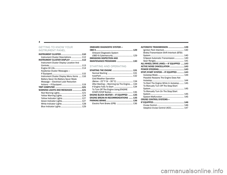
GETTING TO KNOW YOUR
INSTRUMENT PANEL
INSTRUMENT CLUSTER....................................... 110
Instrument Cluster Descriptions .................. 112
INSTRUMENT CLUSTER DISPLAY ..................... 112
Instrument Cluster Display Location And
Controls .......................................................... 113
Engine Oil Life ................................................ 114
KeySense Cluster Messages —
If Equipped..................................................... 115
Instrument Cluster Display Menu Items ..... 116
Battery Saver On/Battery Saver Mode
Message — Electrical Load Reduction
Actions — If Equipped.................................... 119
TRIP COMPUTER ................................................. 121
WARNING LIGHTS AND MESSAGES ................. 121
Red Warning Lights ....................................... 121
Yellow Warning Lights ................................... 124Yellow Indicator Lights .................................. 127
Green Indicator Lights................................... 127White Indicator Lights ................................... 128Blue Indicator Lights ..................................... 129 ONBOARD DIAGNOSTIC SYSTEM —
OBD II .................................................................... 129
Onboard Diagnostic System
(OBD II) Cybersecurity ................................... 129
EMISSIONS INSPECTION AND
MAINTENANCE PROGRAMS ............................. 130
STARTING AND OPERATING
STARTING THE ENGINE ...................................... 131
Normal Starting ............................................ 131
AutoPark ........................................................ 132Cold Weather Operation
(Below –22°F Or −30°C) ............................ 134
After Starting — Warming Up The Engine..... 134
If Engine Fails To Start ................................. 134
To Turn Off The Engine Using ENGINE
START/STOP Button ...................................... 135
ENGINE BLOCK HEATER — IF EQUIPPED ........ 135
ENGINE BREAK-IN RECOMMENDATIONS ....... 135
PARKING BRAKE ................................................. 136
Electric Park Brake (EPB) ............................ 136 AUTOMATIC TRANSMISSION ............................. 139
Ignition Park Interlock................................... 140
Brake/Transmission Shift Interlock (BTSI)
System ........................................................... 140
9-Speed Automatic Transmission ................ 140Gear Ranges .................................................. 141
ALL-WHEEL DRIVE (AWD) — IF EQUIPPED ...... 143
ACTIVE NOISE CANCELLATION .......................... 143
POWER STEERING............................................... 143
STOP/START SYSTEM — IF EQUIPPED ............. 143 Autostop Mode .............................................. 144
Possible Reasons The Engine Does Not
Autostop......................................................... 144
To Start The Engine While In Autostop ........ 145To Manually Turn Off The Stop/Start
System ........................................................... 145
To Manually Turn On The Stop/Start
System ........................................................... 145
System Malfunction ...................................... 145
CRUISE CONTROL SYSTEMS —
IF EQUIPPED ......................................................... 146
Cruise Control................................................ 146
Adaptive Cruise Control (ACC) ...................... 147
22_RUP_OM_EN_USC_t.book Page 4
Page 9 of 384
7
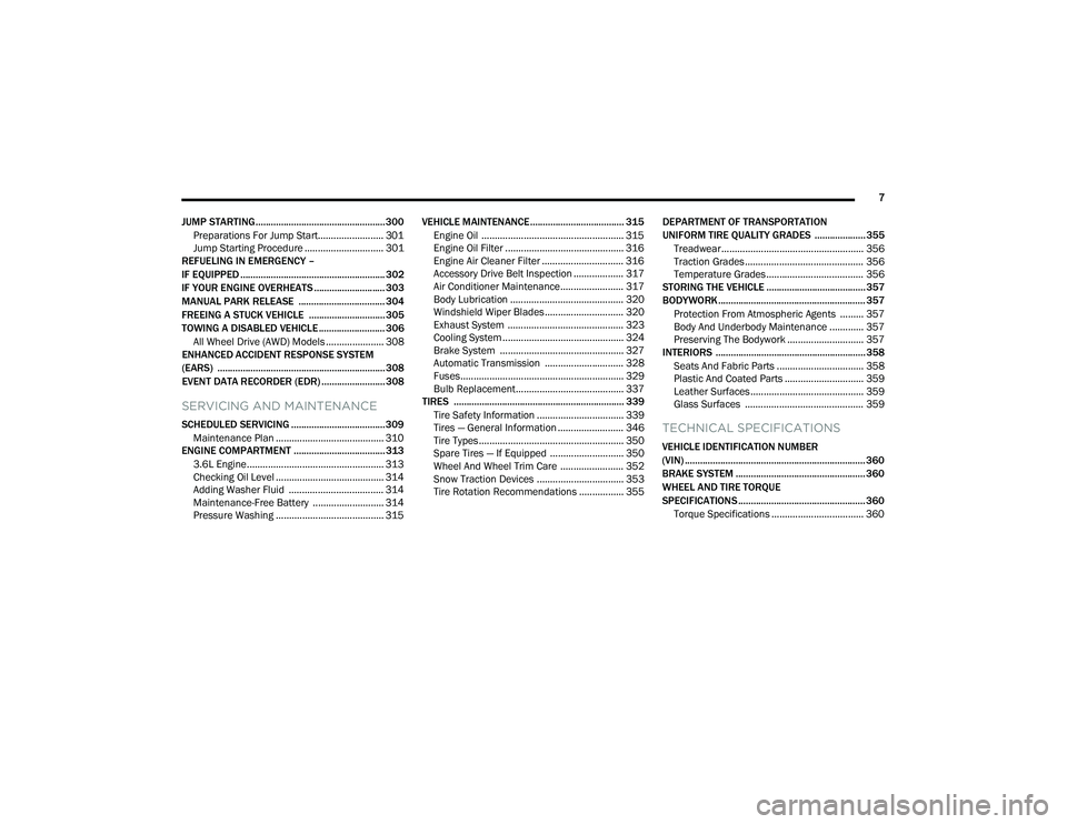
JUMP STARTING................................................... 300 Preparations For Jump Start......................... 301Jump Starting Procedure .............................. 301
REFUELING IN EMERGENCY –
IF EQUIPPED ......................................................... 302
IF YOUR ENGINE OVERHEATS ............................ 303
MANUAL PARK RELEASE .................................. 304
FREEING A STUCK VEHICLE .............................. 305
TOWING A DISABLED VEHICLE .......................... 306
All Wheel Drive (AWD) Models ...................... 308
ENHANCED ACCIDENT RESPONSE SYSTEM
(EARS) .................................................................. 308
EVENT DATA RECORDER (EDR) ......................... 308
SERVICING AND MAINTENANCE
SCHEDULED SERVICING ..................................... 309
Maintenance Plan ......................................... 310
ENGINE COMPARTMENT .................................... 313
3.6L Engine.................................................... 313
Checking Oil Level ......................................... 314
Adding Washer Fluid .................................... 314
Maintenance-Free Battery ........................... 314
Pressure Washing ......................................... 315 VEHICLE MAINTENANCE..................................... 315
Engine Oil ...................................................... 315
Engine Oil Filter ............................................. 316Engine Air Cleaner Filter ............................... 316
Accessory Drive Belt Inspection ................... 317Air Conditioner Maintenance........................ 317
Body Lubrication ........................................... 320Windshield Wiper Blades.............................. 320Exhaust System ............................................ 323
Cooling System .............................................. 324
Brake System ............................................... 327
Automatic Transmission .............................. 328Fuses.............................................................. 329
Bulb Replacement......................................... 337
TIRES ................................................................... 339
Tire Safety Information ................................. 339
Tires — General Information ......................... 346
Tire Types....................................................... 350
Spare Tires — If Equipped ............................ 350
Wheel And Wheel Trim Care ........................ 352
Snow Traction Devices ................................. 353
Tire Rotation Recommendations ................. 355 DEPARTMENT OF TRANSPORTATION
UNIFORM TIRE QUALITY GRADES .................... 355
Treadwear...................................................... 356
Traction Grades ............................................. 356Temperature Grades..................................... 356
STORING THE VEHICLE ....................................... 357
BODYWORK .......................................................... 357
Protection From Atmospheric Agents ......... 357
Body And Underbody Maintenance ............. 357
Preserving The Bodywork ............................. 357
INTERIORS ........................................................... 358
Seats And Fabric Parts ................................. 358
Plastic And Coated Parts .............................. 359
Leather Surfaces........................................... 359
Glass Surfaces ............................................. 359TECHNICAL SPECIFICATIONS
VEHICLE IDENTIFICATION NUMBER
(VIN) ....................................................................... 360
BRAKE SYSTEM ................................................... 360
WHEEL AND TIRE TORQUE
SPECIFICATIONS .................................................. 360Torque Specifications ................................... 360
22_RUP_OM_EN_USC_t.book Page 7
Page 11 of 384
9
INTRODUCTION
Dear Customer,
Congratulations on the purchase of your new Chrysler vehicle. Be assured that it represents precision workmanship, distinctive styling, and high quality.
This Owner's Manual has been prepared with the assistance of service and engineering specialists to acquaint you with the operation and maintenance of your
vehicle. It is supplemented by customer-oriented documents. Within this information, you will find a description of the services that FCA US LLC offers to its
customers as well as the details of the terms and conditions for maintaining its validity. Please take the time to read all of these publications carefully before
driving your vehicle for the first time. Following the instructions, recommendations, tips, and important warnings in this manual will help ensure safe and
enjoyable operation of your vehicle.
This Owner's Manual describes all versions of this vehicle. Options and equipment dedicated to specific markets or versions are not expressly indicated in the
text. Therefore, you should only consider the information that is related to the trim level, engine, and version that you have purchased. Any content introduced
throughout the Owner's Information, which may or may not be applicable to your vehicle, will be identified with the wording “If Equipped” or, if applicable, refer
to the “Hybrid Supplement” for additional information. All data contained in this publication are intended to help you use your vehicle in the best possible way.
FCA US LLC aims at a constant improvement of the vehicles produced. For this reason, it reserves the right to make changes to the model described for technical
and/or commercial reasons. For further information, contact an authorized dealer.
When it comes to service, remember that authorized dealers know your Chrysler vehicle best, have factory-trained technicians, genuine Mopar® parts, and care
about your satisfaction.1
22_RUP_OM_EN_USC_t.book Page 9
Page 98 of 384
96GETTING TO KNOW YOUR VEHICLE
IGNITION OFF OPERATION
The power sunroof switch will remain active for up
to approximately 10 minutes after the ignition
switch is placed in the OFF position. Opening either
front door will cancel this feature.
NOTE:Ignition off time is programmable through the
Uconnect system Úpage 188.
SUNROOF MAINTENANCE
Use only a non-abrasive cleaner and a soft cloth to
clean the glass panel. Periodically check for and
clear out any debris that may have collected in the
tracks.
HOOD
OPENING
If applicable, refer to the “Hybrid Supplement” for
additional information.
The hood release lever (to open the primary latch)
and safety latch (to open the secondary latch)
must be released to open the hood.
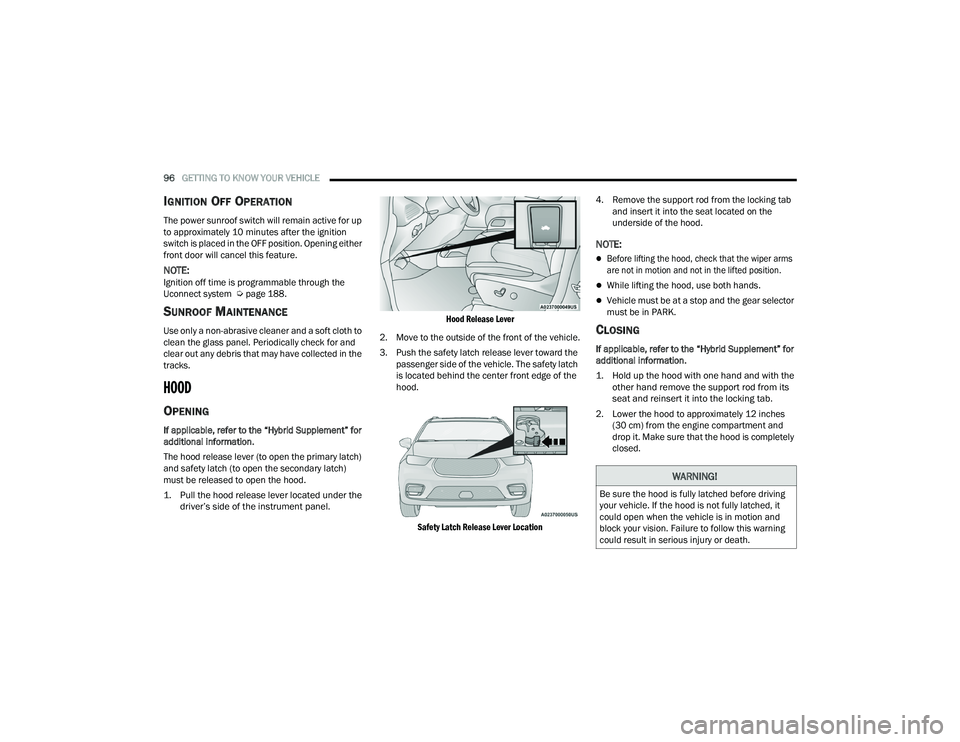
1. Pull the hood release lever located under the
driver’s side of the instrument panel.
Hood Release Lever
2. Move to the outside of the front of the vehicle.
3. Push the safety latch release lever toward the passenger side of the vehicle. The safety latch
is located behind the center front edge of the
hood.
Safety Latch Release Lever Location
4. Remove the support rod from the locking tab
and insert it into the seat located on the
underside of the hood.
NOTE:
Before lifting the hood, check that the wiper arms
are not in motion and not in the lifted position.
While lifting the hood, use both hands.
Vehicle must be at a stop and the gear selector
must be in PARK.
CLOSING
If applicable, refer to the “Hybrid Supplement” for
additional information.
1. Hold up the hood with one hand and with the other hand remove the support rod from its
seat and reinsert it into the locking tab.
2. Lower the hood to approximately 12 inches (30 cm) from the engine compartment and
drop it. Make sure that the hood is completely
closed.
WARNING!
Be sure the hood is fully latched before driving
your vehicle. If the hood is not fully latched, it
could open when the vehicle is in motion and
block your vision. Failure to follow this warning
could result in serious injury or death.
22_RUP_OM_EN_USC_t.book Page 96
Page 104 of 384
102GETTING TO KNOW YOUR VEHICLE
The vacuum will operate in two modes:
Ignition in the ACC position: Engine remains off,
and vacuum usage is limited to 10 minutes.
Ignition in the START position: Engine is running,
and vacuum usage is unlimited until the
vehicle’s battery level falls below 60%.
NOTE:The vacuum will not operate when the ignition is in
the OFF position, or in the ON/RUN position with
the engine off. For more information on ignition
positions, see Ú page 18.
1. Before Using Vacuum:
Accessory (ACC) Mode Operation - For up to
10 minutes of operation
Always apply the parking brake, shift the trans -
mission into PARK, and push ignition button to
place ignition in Accessory (ACC) mode. The
engine will not be running in this mode. Do not
leave the key fob in or near the vehicle, or in a
location accessible to children.
NOTE:The vacuum system will run for 10 minutes off
battery power and then the vacuum will shut down.
A low battery indication light (LOW PWR) located
below the vacuum nozzle storage location will
come on one minute before the vacuum shuts
down. Engine Running (START) Operation - For more
than 10 minutes of operation
Position vehicle outdoors and fully open all
side windows.
Always apply the parking brake, shift the
transmission into PARK, and leave engine
running.
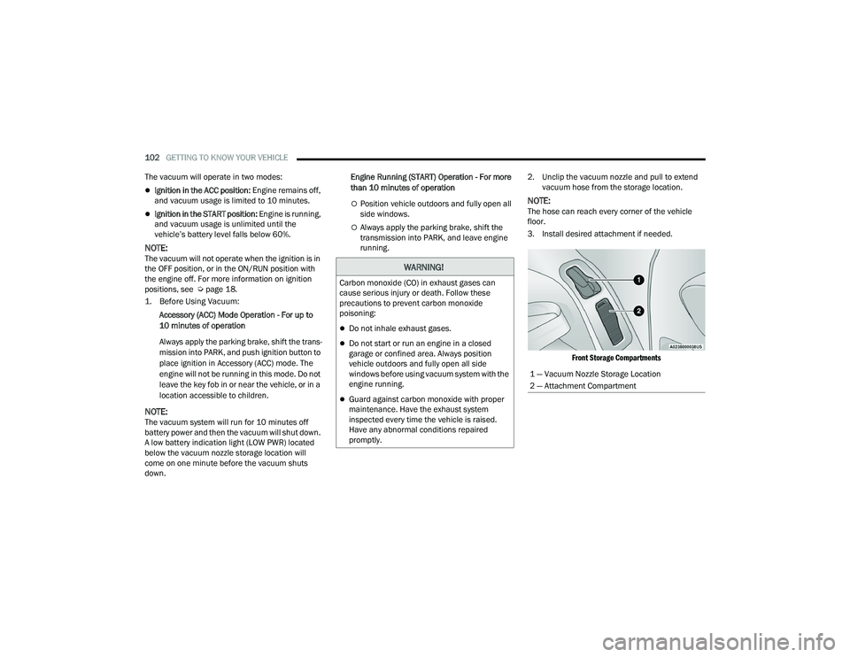
2. Unclip the vacuum nozzle and pull to extend
vacuum hose from the storage location.
NOTE:The hose can reach every corner of the vehicle
floor.
3. Install desired attachment if needed.
Front Storage Compartments
WARNING!
Carbon monoxide (CO) in exhaust gases can
cause serious injury or death. Follow these
precautions to prevent carbon monoxide
poisoning:
Do not inhale exhaust gases.
Do not start or run an engine in a closed
garage or confined area. Always position
vehicle outdoors and fully open all side
windows before using vacuum system with the
engine running.
Guard against carbon monoxide with proper
maintenance. Have the exhaust system
inspected every time the vehicle is raised.
Have any abnormal conditions repaired
promptly.
1 — Vacuum Nozzle Storage Location
2 — Attachment Compartment
22_RUP_OM_EN_USC_t.book Page 102
Page 116 of 384
114GETTING TO KNOW YOUR INSTRUMENT PANEL
ENGINE OIL LIFE
Your vehicle is equipped with an engine oil
change indicator system. The “Oil Change
Required” message will display for approxi-
mately five seconds after a single chime has
sounded, to indicate it is time to change the
engine oil. The engine oil change indicator
system is duty cycle based, which means the
engine oil change interval may fluctuate, depen -
dent upon your personal driving style.
Unless reset, this message will continue to
display each time the ignition is cycled to the
ON/RUN position.
To reset the oil change indicator after
performing the scheduled maintenance, refer to
the following procedure.
NOTE:This procedure should only be performed after
scheduled maintenance is completed. Resetting
oil life other than when associated with a
scheduled maintenance may result in damage due
to not properly maintaining the engine oil. Oil Life Reset
1. Without pressing the brake pedal, push the
ENGINE START/STOP button and place the
ignition in the ON/RUN position (do not start
the vehicle.)
2. Push the OK button to enter the instrument
cluster display menu screen.
3. Push and release the down arrow button to
access the ”Vehicle Info” menu screen.
4. Push the left arrow button or right arrow
button to access the “Oil Life” submenu.
5. Hold the OK button to reset the “Oil Life” to
100%.
6. Push the up arrow button to exit the
instrument cluster display menu screen. Secondary Method For Oil Life Reset Procedure
1. Without pushing the brake pedal, place the
ignition in the ON/RUN position (do not start
the engine).
2. Fully press the accelerator pedal, slowly, three times within 10 seconds.
3. Without pushing the brake pedal, place the ignition in the OFF position.
NOTE:If the indicator message illuminates when you start
the vehicle, the oil change indicator system did not
reset. If necessary, repeat this procedure.
22_RUP_OM_EN_USC_t.book Page 114
Page 129 of 384
GETTING TO KNOW YOUR INSTRUMENT PANEL127
Please note that the TPMS is not a substitute for
proper tire maintenance, and it is the driver’s
responsibility to maintain correct tire pressure,
even if underinflation has not reached the level to
trigger illumination of the TPMS low tire pressure
telltale.
Your vehicle has also been equipped with a TPMS
malfunction indicator to indicate when the system
is not operating properly. The TPMS malfunction
indicator is combined with the low tire pressure
telltale. When the system detects a malfunction,
the telltale will flash for approximately one minute
and then remain continuously illuminated. This
sequence will continue upon subsequent vehicle
start-ups as long as the malfunction exists. When
the malfunction indicator is illuminated, the
system may not be able to detect or signal low tire
pressure as intended. TPMS malfunctions may
occur for a variety of reasons, including the
installation of replacement or alternate tires or
wheels on the vehicle that prevent the TPMS from
functioning properly. Always check the TPMS
malfunction telltale after replacing one or more
tires or wheels on your vehicle to ensure that the
replacement or alternate tires and wheels allow
the TPMS to continue to function properly.
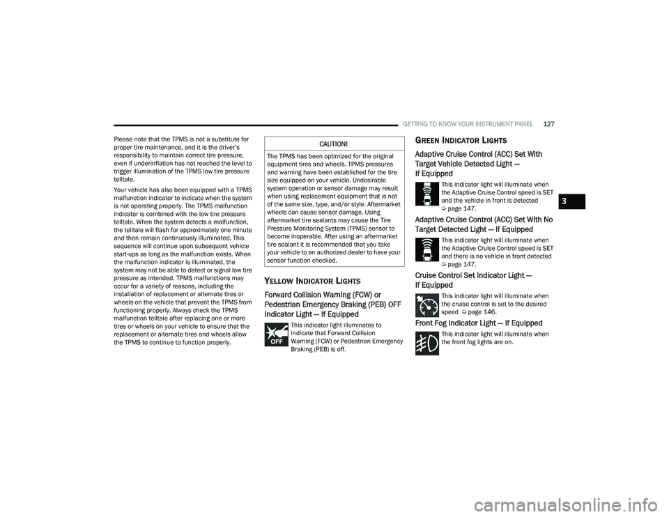
YELLOW INDICATOR LIGHTS
Forward Collision Warning (FCW) or
Pedestrian Emergency Braking (PEB) OFF
Indicator Light — If Equipped
This indicator light illuminates to
indicate that Forward Collision
Warning (FCW) or Pedestrian Emergency
Braking (PEB) is off.
GREEN INDICATOR LIGHTS
Adaptive Cruise Control (ACC) Set With
Target Vehicle Detected Light —
If Equipped
This indicator light will illuminate when
the Adaptive Cruise Control speed is SET
and the vehicle in front is detected
Ú page 147.
Adaptive Cruise Control (ACC) Set With No
Target Detected Light — If Equipped
This indicator light will illuminate when
the Adaptive Cruise Control speed is SET
and there is no vehicle in front detected
Úpage 147.
Cruise Control Set Indicator Light —
If Equipped
This indicator light will illuminate when
the cruise control is set to the desired
speed Ú page 146.
Front Fog Indicator Light — If Equipped
This indicator light will illuminate when
the front fog lights are on.
CAUTION!
The TPMS has been optimized for the original
equipment tires and wheels. TPMS pressures
and warning have been established for the tire
size equipped on your vehicle. Undesirable
system operation or sensor damage may result
when using replacement equipment that is not
of the same size, type, and/or style. Aftermarket
wheels can cause sensor damage. Using
aftermarket tire sealants may cause the Tire
Pressure Monitoring System (TPMS) sensor to
become inoperable. After using an aftermarket
tire sealant it is recommended that you take
your vehicle to an authorized dealer to have your
sensor function checked.
3
22_RUP_OM_EN_USC_t.book Page 127
Page 132 of 384
130GETTING TO KNOW YOUR INSTRUMENT PANEL
EMISSIONS INSPECTION AND
MAINTENANCE PROGRAMS
In some localities, it may be a legal requirement to
pass an inspection of your vehicle's emissions
control system. Failure to pass could prevent
vehicle registration.
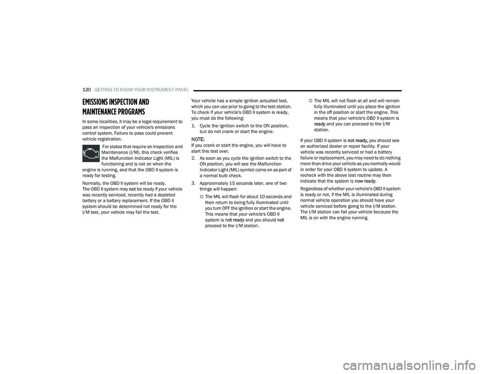
For states that require an Inspection and
Maintenance (I/M), this check verifies
the Malfunction Indicator Light (MIL) is
functioning and is not on when the
engine is running, and that the OBD II system is
ready for testing.
Normally, the OBD II system will be ready.
The OBD II system may not be ready if your vehicle
was recently serviced, recently had a depleted
battery or a battery replacement. If the OBD II
system should be determined not ready for the
I/M test, your vehicle may fail the test. Your vehicle has a simple ignition actuated test,
which you can use prior to going to the test station.
To check if your vehicle's OBD II system is ready,
you must do the following:
1. Cycle the ignition switch to the ON position,
but do not crank or start the engine.
NOTE:If you crank or start the engine, you will have to
start this test over.
2. As soon as you cycle the ignition switch to the ON position, you will see the Malfunction
Indicator Light (MIL) symbol come on as part of
a normal bulb check.
3. Approximately 15 seconds later, one of two things will happen:
The MIL will flash for about 10 seconds and
then return to being fully illuminated until
you turn OFF the ignition or start the engine.
This means that your vehicle's OBD II
system is not ready and you should not
proceed to the I/M station.
The MIL will not flash at all and will remain
fully illuminated until you place the ignition
in the off position or start the engine. This
means that your vehicle's OBD II system is
ready and you can proceed to the I/M
station.
If your OBD II system is not ready, you should see
an authorized dealer or repair facility. If your
vehicle was recently serviced or had a battery
failure or replacement, you may need to do nothing
more than drive your vehicle as you normally would
in order for your OBD II system to update. A
recheck with the above test routine may then
indicate that the system is now ready.
Regardless of whether your vehicle's OBD II system
is ready or not, if the MIL is illuminated during
normal vehicle operation you should have your
vehicle serviced before going to the I/M station.
The I/M station can fail your vehicle because the
MIL is on with the engine running.
22_RUP_OM_EN_USC_t.book Page 130